US9510862B2 - Revision connector for spinal constructs - Google Patents
Revision connector for spinal constructs Download PDFInfo
- Publication number
- US9510862B2 US9510862B2 US12/817,920 US81792010A US9510862B2 US 9510862 B2 US9510862 B2 US 9510862B2 US 81792010 A US81792010 A US 81792010A US 9510862 B2 US9510862 B2 US 9510862B2
- Authority
- US
- United States
- Prior art keywords
- bone
- extension member
- recited
- extender system
- anchor
- Prior art date
- Legal status (The legal status is an assumption and is not a legal conclusion. Google has not performed a legal analysis and makes no representation as to the accuracy of the status listed.)
- Active, expires
Links
Images


Classifications
-
- A—HUMAN NECESSITIES
- A61—MEDICAL OR VETERINARY SCIENCE; HYGIENE
- A61B—DIAGNOSIS; SURGERY; IDENTIFICATION
- A61B17/00—Surgical instruments, devices or methods, e.g. tourniquets
- A61B17/56—Surgical instruments or methods for treatment of bones or joints; Devices specially adapted therefor
- A61B17/58—Surgical instruments or methods for treatment of bones or joints; Devices specially adapted therefor for osteosynthesis, e.g. bone plates, screws, setting implements or the like
- A61B17/68—Internal fixation devices, including fasteners and spinal fixators, even if a part thereof projects from the skin
- A61B17/70—Spinal positioners or stabilisers ; Bone stabilisers comprising fluid filler in an implant
- A61B17/7001—Screws or hooks combined with longitudinal elements which do not contact vertebrae
- A61B17/7002—Longitudinal elements, e.g. rods
- A61B17/7019—Longitudinal elements having flexible parts, or parts connected together, such that after implantation the elements can move relative to each other
- A61B17/7025—Longitudinal elements having flexible parts, or parts connected together, such that after implantation the elements can move relative to each other with a sliding joint
-
- A—HUMAN NECESSITIES
- A61—MEDICAL OR VETERINARY SCIENCE; HYGIENE
- A61B—DIAGNOSIS; SURGERY; IDENTIFICATION
- A61B17/00—Surgical instruments, devices or methods, e.g. tourniquets
- A61B17/56—Surgical instruments or methods for treatment of bones or joints; Devices specially adapted therefor
- A61B17/58—Surgical instruments or methods for treatment of bones or joints; Devices specially adapted therefor for osteosynthesis, e.g. bone plates, screws, setting implements or the like
- A61B17/68—Internal fixation devices, including fasteners and spinal fixators, even if a part thereof projects from the skin
- A61B17/70—Spinal positioners or stabilisers ; Bone stabilisers comprising fluid filler in an implant
- A61B17/7001—Screws or hooks combined with longitudinal elements which do not contact vertebrae
-
- A—HUMAN NECESSITIES
- A61—MEDICAL OR VETERINARY SCIENCE; HYGIENE
- A61B—DIAGNOSIS; SURGERY; IDENTIFICATION
- A61B17/00—Surgical instruments, devices or methods, e.g. tourniquets
- A61B17/16—Bone cutting, breaking or removal means other than saws, e.g. Osteoclasts; Drills or chisels for bones; Trepans
- A61B17/1662—Bone cutting, breaking or removal means other than saws, e.g. Osteoclasts; Drills or chisels for bones; Trepans for particular parts of the body
- A61B17/1671—Bone cutting, breaking or removal means other than saws, e.g. Osteoclasts; Drills or chisels for bones; Trepans for particular parts of the body for the spine
-
- A—HUMAN NECESSITIES
- A61—MEDICAL OR VETERINARY SCIENCE; HYGIENE
- A61B—DIAGNOSIS; SURGERY; IDENTIFICATION
- A61B17/00—Surgical instruments, devices or methods, e.g. tourniquets
- A61B17/56—Surgical instruments or methods for treatment of bones or joints; Devices specially adapted therefor
- A61B17/58—Surgical instruments or methods for treatment of bones or joints; Devices specially adapted therefor for osteosynthesis, e.g. bone plates, screws, setting implements or the like
- A61B17/68—Internal fixation devices, including fasteners and spinal fixators, even if a part thereof projects from the skin
- A61B17/70—Spinal positioners or stabilisers ; Bone stabilisers comprising fluid filler in an implant
- A61B17/7001—Screws or hooks combined with longitudinal elements which do not contact vertebrae
- A61B17/7002—Longitudinal elements, e.g. rods
-
- A—HUMAN NECESSITIES
- A61—MEDICAL OR VETERINARY SCIENCE; HYGIENE
- A61B—DIAGNOSIS; SURGERY; IDENTIFICATION
- A61B17/00—Surgical instruments, devices or methods, e.g. tourniquets
- A61B17/56—Surgical instruments or methods for treatment of bones or joints; Devices specially adapted therefor
- A61B17/58—Surgical instruments or methods for treatment of bones or joints; Devices specially adapted therefor for osteosynthesis, e.g. bone plates, screws, setting implements or the like
- A61B17/68—Internal fixation devices, including fasteners and spinal fixators, even if a part thereof projects from the skin
- A61B17/70—Spinal positioners or stabilisers ; Bone stabilisers comprising fluid filler in an implant
- A61B17/7001—Screws or hooks combined with longitudinal elements which do not contact vertebrae
- A61B17/7032—Screws or hooks with U-shaped head or back through which longitudinal rods pass
-
- A—HUMAN NECESSITIES
- A61—MEDICAL OR VETERINARY SCIENCE; HYGIENE
- A61B—DIAGNOSIS; SURGERY; IDENTIFICATION
- A61B17/00—Surgical instruments, devices or methods, e.g. tourniquets
- A61B17/56—Surgical instruments or methods for treatment of bones or joints; Devices specially adapted therefor
- A61B17/58—Surgical instruments or methods for treatment of bones or joints; Devices specially adapted therefor for osteosynthesis, e.g. bone plates, screws, setting implements or the like
- A61B17/68—Internal fixation devices, including fasteners and spinal fixators, even if a part thereof projects from the skin
- A61B17/70—Spinal positioners or stabilisers ; Bone stabilisers comprising fluid filler in an implant
- A61B17/7062—Devices acting on, attached to, or simulating the effect of, vertebral processes, vertebral facets or ribs ; Tools for such devices
- A61B17/7068—Devices comprising separate rigid parts, assembled in situ, to bear on each side of spinous processes; Tools therefor
-
- A—HUMAN NECESSITIES
- A61—MEDICAL OR VETERINARY SCIENCE; HYGIENE
- A61B—DIAGNOSIS; SURGERY; IDENTIFICATION
- A61B17/00—Surgical instruments, devices or methods, e.g. tourniquets
- A61B17/56—Surgical instruments or methods for treatment of bones or joints; Devices specially adapted therefor
- A61B17/58—Surgical instruments or methods for treatment of bones or joints; Devices specially adapted therefor for osteosynthesis, e.g. bone plates, screws, setting implements or the like
- A61B17/68—Internal fixation devices, including fasteners and spinal fixators, even if a part thereof projects from the skin
- A61B17/70—Spinal positioners or stabilisers ; Bone stabilisers comprising fluid filler in an implant
- A61B17/7001—Screws or hooks combined with longitudinal elements which do not contact vertebrae
- A61B17/7002—Longitudinal elements, e.g. rods
- A61B17/7004—Longitudinal elements, e.g. rods with a cross-section which varies along its length
- A61B17/7007—Parts of the longitudinal elements, e.g. their ends, being specially adapted to fit around the screw or hook heads
-
- A—HUMAN NECESSITIES
- A61—MEDICAL OR VETERINARY SCIENCE; HYGIENE
- A61B—DIAGNOSIS; SURGERY; IDENTIFICATION
- A61B17/00—Surgical instruments, devices or methods, e.g. tourniquets
- A61B17/56—Surgical instruments or methods for treatment of bones or joints; Devices specially adapted therefor
- A61B17/58—Surgical instruments or methods for treatment of bones or joints; Devices specially adapted therefor for osteosynthesis, e.g. bone plates, screws, setting implements or the like
- A61B17/68—Internal fixation devices, including fasteners and spinal fixators, even if a part thereof projects from the skin
- A61B17/70—Spinal positioners or stabilisers ; Bone stabilisers comprising fluid filler in an implant
- A61B17/7001—Screws or hooks combined with longitudinal elements which do not contact vertebrae
- A61B17/7002—Longitudinal elements, e.g. rods
- A61B17/7011—Longitudinal element being non-straight, e.g. curved, angled or branched
-
- A—HUMAN NECESSITIES
- A61—MEDICAL OR VETERINARY SCIENCE; HYGIENE
- A61B—DIAGNOSIS; SURGERY; IDENTIFICATION
- A61B17/00—Surgical instruments, devices or methods, e.g. tourniquets
- A61B17/56—Surgical instruments or methods for treatment of bones or joints; Devices specially adapted therefor
- A61B17/58—Surgical instruments or methods for treatment of bones or joints; Devices specially adapted therefor for osteosynthesis, e.g. bone plates, screws, setting implements or the like
- A61B17/68—Internal fixation devices, including fasteners and spinal fixators, even if a part thereof projects from the skin
- A61B17/70—Spinal positioners or stabilisers ; Bone stabilisers comprising fluid filler in an implant
- A61B17/7049—Connectors, not bearing on the vertebrae, for linking longitudinal elements together
Definitions
- the present disclosure relates generally to orthopedics, and in particular relates to implants and methods for extending existing posterior vertebral screw assemblies to additional levels.
- the patient's existing hardware must be identified via X-rays or fluoroscopy and, once identified, the surgeon must determine if the same make and model of hardware is available to the hospital or still on the market. The surgeon must also determine if his experience will allow him to revise and the existing hardware and/or add on new hardware, as some existing hardware systems are more difficult to revise or install. Based on these determinations, the surgeon may decide to revise using new hardware.
- an extender system is configured to be operatively coupled to a vertebral implant that is secured to a vertebra, the vertebral implant including a first bone anchor and a first anchor seat that receives the first bone anchor.
- the extender system includes an extension member including a body and an engagement member coupled to the body.
- the extender system further includes a fastener that is configured to couple the extension member to the vertebral implant.
- the extender system further includes a second bone anchor that is configured to attach the extension member to an underlying bone disposed adjacent the vertebra.
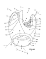
- FIG. 1A is a perspective view of a bone fixation assembly constructed in accordance with one embodiment including a plurality of bone fixation elements connected to a previously implanted spine fixation rod, and illustrated schematically as each being previously secured to a vertebra;
- FIG. 1B is a perspective view of one of the bone fixation elements illustrated in FIG. 1A constructed in accordance with one embodiment, including an anchor seat, a bone anchor, a collet, and a locking cap;
- FIG. 2 is a perspective view of the spine fixation rod illustrated in FIG. 1A ;
- FIG. 3 is a perspective view of the bone anchor illustrated in FIG. 1B ;
- FIG. 4 is a perspective view of the anchor seat illustrated in FIG. 1B ;
- FIG. 5A is an exploded perspective view of the locking cap illustrated in FIG. 1B ;
- FIG. 5B is a top plan view of the locking cap illustrated in FIG. 5A ;
- FIG. 5C is a sectional side elevation view of the locking cap illustrated in FIG. 5B ;
- FIG. 6 is a perspective view of the collet illustrated in FIG. 1B ;
- FIG. 7A is a sectional side elevation view of the bone fixation element illustrated in FIG. 1B taken along line 7 A- 7 A, with the locking cap removed, to illustrate a vertebral screw assembly;
- FIG. 7B is a sectional side elevation view similar to FIG. 7B , but showing a spine fixation rod extending through the anchor seat, and a locking cap affixed to the anchor seat;
- FIGS. 8A-D are schematic views illustrating a method for assembling the bone fixation element illustrated in FIG. 1A ;
- FIG. 9 is a perspective view similar to FIG. 1A , but showing a plurality of superior and inferior vertebrae with respect to the previously secured vertebrae;
- FIG. 10A is an exploded view of an extender system constructed in accordance with one embodiment
- FIG. 10B is a sectional view through a portion of the extender system illustrated in FIG. 10A ;
- FIG. 10C is a perspective view of the extender system illustrated in FIG. 10A coupled to a previously implanted bone fixation assembly;
- FIG. 10D is an enlarged side elevation view of a portion of the extender system illustrated in FIG. 10A coupled to a previously implanted bone fixation assembly;
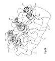
- FIG. 11A is an exploded view of a cascading extender system to be implanted into a plurality of vertebrae;
- FIG. 11B is a perspective view of a pair of rows of the cascading extender system illustrated in FIG. 11A implanted into the vertebrae;
- FIG. 11C is a perspective view of parallel rows of fixation elements connected by a cross bar
- FIG. 11D is a perspective view of the fixation elements connected by a cross bar and implanted into a plurality of schematically illustrated vertebrae
- FIG. 12 is a perspective view of the extender system illustrated in FIG. 10A , but including an extension member constructed in accordance with an alternative embodiment
- FIG. 13 is a perspective view of the extender system illustrated in FIG. 10A , configured to connect a bone fixation element to a previously-implanted translaminar screw;
- FIG. 14A is a perspective view of a pair of the extender systems illustrated in FIG. 10A configured to connect an occiput to a spine;
- FIG. 14B is another perspective view of one of the extender systems illustrated in FIG. 14A ;
- FIG. 14C is a perspective view of the extender systems illustrated in FIG. 14A connected between an occiput and a spine;
- FIG. 14D is another perspective view of one of the implanted extender systems illustrated in FIG. 14C .
- a bone fixation assembly 20 includes one or more bone fixation elements 22 , and four bone fixation elements 22 A-D as illustrated in FIG. 1A .
- each bone fixation element 22 extends vertically along an axial direction A, and generally horizontally along a radial direction R that extends perpendicular to the axial direction A.
- the radial direction R includes a longitudinal direction L and a lateral direction LA that extends perpendicular to the longitudinal direction L.
- the bone fixation element 22 defines an upper or posterior end 21 and a lower or inferior end 23 , such that the directional terms “upper” and “lower” and derivatives thereof refer to a direction from the lower end 23 towards the upper end 21 , and from the upper end 21 towards the lower end 23 , respectively.
- the words “inward,” “outward,” “upper,” “lower,” “distal,” and “proximal,” refer to directions toward or away from, respectively, the geometric center of the bone fixation assembly 20 and its components.
- the words, “anterior”, “posterior”, “superior,” “inferior” and related words and/or phrases designate preferred positions and orientations in the human body to which reference is made and are not meant to be limiting.
- round structures define diameters as described herein, the round structures could be replaced with alternative (e.g., polygonal) structures which would define alternative cross-sectional dimensions opposed to diameters.
- the term “diameter” as used herein is intended to include all such alternatives unless otherwise specified.
- the terminology includes the above-listed words, derivatives thereof and words of similar import.
- the directional terms are used herein with reference to the orientation of the bone fixation assembly 20 and its components as illustrated, and that the actual orientation of the bone fixation assembly 20 and its components may change during use.
- the axial direction is illustrated as extending along a vertical direction
- the radial direction is illustrated as extending along a horizontal direction, however the directions that encompass the various directions may differ during use, depending, for instance, on the desired orientation of the bone fixation assembly 20 during use.
- the directional terms are used herein merely for the purposes of clarity and convenience only, in a non-limiting manner.
- the bone fixation assembly 20 includes a plurality of bone fixation elements, such as bone fixation elements 22 A-D, connected by a spine fixation rod 24 that extends along a longitudinal axis L.
- the bone fixation elements 22 A-D each include a bone anchor 30 that is implanted (e.g., screwed) into a corresponding vertebra 27 A-D.
- the bone fixation elements 22 A-D can be implanted into the posterior region of the spine, or any suitable alternative region of the spine, for instance into the pedicle or other spinal region.
- the bone anchor 30 can be provided as a screw, hook, or alternatively constructed top loading bone anchor configured to attach to an underlying vertebra.
- the bone fixation assembly 20 and its components can be made from titanium-aluminum-niobium alloy (TAN), implant-grade 316L stainless steel, or any suitable alternative implant-grade material.
- TAN titanium-aluminum-niobium alloy
- 316L stainless steel or any suitable alternative implant-grade material.
- the bone fixation elements 22 A-D will be described as and may be generally implanted in the spine, for instance at the posterior portion of a lumbar, thoracic, or cervical vertebral body.
- the assembly 20 fixes the relative position of the vertebrae (illustrated schematically at 27 A-D).
- the bone fixation elements 22 A-D can be referred to as vertebral implants
- the spine fixation rod 24 can be referred to as a spine fixation rod
- the bone fixation assembly 20 can be referred to as a vertebral implant.
- the bone fixation assembly 20 can also be used for fixation of other parts of the body, such as joints, long bones, or bones in the hands, face, feet, extremities, cranium, and the like.
- the spine fixation rod 24 is elongate along a longitudinal axis L, and includes a body 25 that is cylindrical or tubular in shape.
- the longitudinal axis L extends generally in a cranial-caudal direction when the bone fixation assembly is affixed to the spine.
- the rod body 25 may include, but is not limited to, a solid body, a non-solid body, a flexible or dynamic body, or the like, and can assume any alternative shape as desired. It should thus be appreciated that the bone fixation assembly 20 is not limited in use to any particular spine fixation rod 24 .
- the bone fixation element 22 generally includes a vertebral implant 75 , and a locking cap 34 .
- the vertebral implant 75 is illustrated as including a bone anchor seat 26 , a collet 28 disposed inside the anchor seat 26 , a bone anchor 30 (shown as a threaded bone screw) having a head portion 33 (see FIG. 3 ) attached to the collet 28 .
- the locking cap 34 is installed in the anchor seat 26 at a location above the collet 28 , such that the spine fixation rod 24 is located in a rod slot 36 that is disposed, and as illustrated defined, between the collet 28 and the locking cap 34 .
- the bone anchor 30 is configured as a bone screw, or vertebral screw, that includes an externally threaded shaft 31 coupled at its upper end to an enlarged curved head 33 .
- the shaft 31 extends axially along a central axis B of rotation, and can define any suitable diameter, length, and thread design so as to engage the underlying bone, such as a vertebra 27 .
- the shaft 31 can be unthreaded so as to define a pin or a nail if desired.
- the bone anchor 30 is not limited to any particular type of shaft 31 .
- the bone anchor 30 may also be cannulated and fenestrated such that openings extend radially outward from a central hollow channel in a cannulated shaft to urge fluid out of the bone anchor 30 during injection or draw fluid into the central hollow channel from the radial sides of the anchor during extraction of material adjacent the anchor if desired.
- the bone anchor 30 further includes a vertically extending neck 35 connected between the shaft 31 and the head 33 .
- the neck 35 is illustrated as extending axially in a direction parallel to axis B, and includes an outer neck surface 37 that defines a neck diameter, which is less than the diameter of the head 33 .
- the head 33 can define at least a partially spherical curvature, such as a semi-spherical curvature, or can alternatively define any suitable curvature as desired to facilitate rotation with respect to the collet 28 as is described in more detail below.
- the head 33 also includes a drive surface 39 configured to receive a corresponding tip of a drive tool, such as a screw driver configured to rotate the bone anchor 30 into engagement with the vertebrae 27 or other underlying bone surface.
- the drive surface 39 can define a hexagon, a star drive pattern, a Phillips head pattern, a slot for a screw driver, threads configured to receive corresponding threads of a threaded drive post, or any suitable drive tool engaging structure as desired.
- the anchor seat 26 includes an anchor seat body 38 that can be described as a generally cylindrical tubular body extending centrally along an axial axis A that extends generally in the anterior-posterior direction when the bone fixation element is implanted in the underlying vertebra.
- the body 38 includes a base 40 and a pair of spaced opposing arms 42 extending out (up in illustrated the orientation) from the base 40 .
- the arms 42 can be substantially identically or identically constructed.
- the arms 42 define corresponding upper ends 46 that are also the upper ends of the body 38 , and define an upper opening 48 .
- the base 40 defines a lower end 50 that is also the lower end of the body 38 , and defines a lower opening 52 .
- the body 38 defines an axial bore 54 extending from the lower opening 52 to the upper opening 48 .
- the body 38 includes opposing support walls 56 and a pair of spaced opposing spacer walls 58 connected between the support walls 56 .
- the support walls 56 can be substantially identically or identically constructed, and the spacer walls 58 can likewise be substantially identically or identically constructed.
- the arms 42 extend up from respective support walls 56 , and can be shaped as desired. As illustrated, the arms 42 are arc-shaped with the axis of the arc passing through the plane of symmetry that bisects the anchor seat 26 .
- Each arm 42 extends circumferentially about its axis less than 180°, such as between 60° and 150°, for instance approximately 90°. For instance, each arm 42 can extend circumferentially 90.5° about its axis.
- a gap G extends circumferentially between adjacent circumferentially outer ends of the arms 42 .
- the opposing gaps G are in alignment with the axial bore 54 .
- the arms 42 can be disposed radially opposite each other such that the gaps G, in combination with the aligned portion of the axial bore 54 , define a rod-receiving channel 36 that is sized and configured to receive the spine fixation rod 24 such that the spine fixation rod 24 extends through the bone fixation element 22 .
- the gaps G are aligned in the longitudinal direction.
- the spine fixation rod 24 can thus extend through the opposing gaps G and the axial bore 54 .
- the arms 42 define radially inner and outer surfaces 60 and 62 , respectively.
- the inner surfaces 60 define threads 62 , and are configured to threadedly receive the locking cap 34 , as will now be described.
- the locking cap 34 is illustrated as a set screw 64 and a saddle 66 operatively coupled to the set screw 64 .
- the set screw 64 includes a generally cylindrical set screw body 65 having external threads 68 configured to threadedly engage the threads 62 formed on the inner surfaces 60 of the arms 42 .
- the threads 68 and 62 can incorporate inclined load flanks forming an angle with respect to the axis A of the bone fixation element 22 .
- the load flanks may converge so that the top surface of the thread and the bottom surface of the thread converge.
- the angle may be between 0 degrees (0°) and 30 degrees (30°), and in one embodiment can be about five degrees (5°).
- the threads may take on any alternative form as desired, including negative load threads, perpendicular threads, buttress threads, or the like.
- the externally threaded set screw 64 generally provides flexibility when inserting the spine fixation rod 24 into the anchor seat body 38 such that the spine fixation rod 24 need not be completely reduced or seated within the body 38 prior to engagement of the locking cap 34 .
- the set screw 64 is configured to be tightened within the anchor seat 26 against the spine fixation rod 24 .
- the locking cap 34 may be constructed as desired for this purpose including, but not limited to, an externally threaded cap, a quarter-turn or partial-turn locking cap, a two-piece screw set, or the like.
- the set screw 64 is illustrated as including a drive surface 70 provided as an internal recess extending vertically down into the upper end of the screw 64 .
- the drive surface has any suitable shape configured to cooperate with a corresponding drive tool for threadedly securing the set screw 64 onto the anchor seat body 38 .
- the drive surface 70 can define any shape as desired, for instance an external hexagon, a star drive pattern, a Phillips head pattern, a slot for a screw driver, a threading for a correspondingly threaded post, or the like.
- the saddle 66 includes a saddle body 72 having a transverse recess 74 extending up into the bottom end of the saddle body 72 .
- the recess 74 can define a round surface that extends about a longitudinally extending axis, such that the recess 74 is configured to receive the spine fixation rod 24 at a rod-contacting surface 76 .
- the rod-contacting surface 76 can include a desired surface finish that adds roughness, such as, for example, a knurl, bead blasting, grooves, or other textured finish that increases surface roughness and enhances rod push through strength.
- the saddle 66 can be coupled to the set screw 64 in any desired manner, including adhesion, mechanical fastening, and the like.
- the saddle 66 includes a stem 78 extending centrally upward from the saddle body 72 .
- the stem 78 is configured to be received in a central bore 32 extending vertically into the lower end of the set screw body 65 , and can be fastened within the central bore with a rivet 80 or other like fastener.
- the saddle 66 is rotatable relative to the set screw 64 , such that the saddle 66 can self-align with the spine fixation rod 24 as the set screw 64 is being rotated with respect to the anchor seat 26 , for instance when the locking cap 34 is being tightened against the spine fixation rod 24 .
- the anchor seat body 38 includes a pair of spaced opposing support walls 56 and a pair of spaced opposing spacer walls 58 connected between the support walls 56 .
- the arms 42 extend up from respective support walls 56 , such that the spacer walls 58 are disposed between the arms 42 .
- Each of the spacer walls 58 defines opposing upper ends 84 and lower ends 82 that can be shaped as desired.
- the upper ends 84 are round in accordance with the illustrated embodiment, such that the upper ends 84 and the circumferentially outer ends of the arms 42 are adjoined to generally define a U-shape from a horizontal view through the gaps G.
- the upper ends 84 define the lower end of the gaps G.
- the upper ends 84 can be shaped to conform generally with the outer surface of the spine fixation rod 24 , such that the upper ends 84 receive and engage the spine fixation rod 24 during use.
- the upper ends 84 can be spaced slightly below the upper surface of the collet 28 , such that the collet 28 supports the spine fixation rod 24 during use, as will be described in more detail below.
- the support walls 56 each define opposing inner and outer surfaces 86 and 88 , respectively.
- the support walls 56 and the spacer walls 58 flare inward toward the central axis A in a downward direction from the arms 42 , and terminate at respective lower ends 90 .
- the inner surfaces 86 of the opposing support walls 56 and spacer walls 58 at the lower end 90 define a distance D therebetween that is less than the distance between opposing radially opposing inner surfaces 60 of the arms 42 .
- the distance D can be less than or greater than the diameter of the head 33 of the bone anchor 30 .
- the inner surfaces 86 flare radially inward toward the central axis A, and toward each other, along a downward direction, and are each connected to bottommost, and innermost, surfaces that define respective abutment walls 92 .
- each abutment wall 92 defines respective inner abutment surfaces 93 that in turn define a distance therebetween that is substantially equal to the diameter of the neck 35 , such that the abutment walls 92 are configured to abut opposing abutment surfaces of the bone anchor, which are illustrated as opposing sides of the outer neck surface 37 when the bone anchor 30 is disposed in the anchor seat 26 .
- the abutment walls 92 can prevent or limit pivoting of the bone anchor 30 relative to the anchor seat 26 in a desired plane.
- the collet 28 includes a collet body 45 that defines a first or upper end 47 sized and configured to contact or support at least a portion of the spine fixation rod 24 when the rod is received within the rod-receiving channel 36 , and a second or lower end 49 sized and configured to contact or otherwise engage, directly or indirectly, a portion of the bone anchor head 33 .
- the collet body 45 is annular, and thus defines an axial bore 53 extending between and through the upper and lower ends 47 and 49 . The axial bore 53 is aligned with the axial bore 54 when the collet 28 is installed in the anchor seat 26 .
- the upper end 47 defines radially opposing upwardly facing seat portions 51 having a curvature or semi-spherical shape corresponding to the outer surface of the spine fixation rod 24 , and is therefore configured to receive or otherwise support at least a portion (e.g., a lower portion) of the rod 24 .
- the lower end 49 defines an inner surface 55 defining a curvature or semi-spherical shape corresponding to the outer surface of the anchor head 33 , and is therefore configured to receive or otherwise engage at least a portion of the head 33 , so that the head can rotate with respect to the collet 28 and the anchor seat 26 , and can further pivot with respect to the collet 28 as permitted by the anchor seat 26 .
- the bone anchor 30 can freely rotate about its axis of rotation B relative to the anchor seat 26 , and thus the anchor seat 26 can likewise rotate about the bone anchor 30 , the rod-receiving channel 36 can be aligned with the spine fixation rod 24 without advancing or withdrawing the bone anchor 30 in or out of the underlying bone.
- the bone anchor 30 can maintain a constant insertion depth in the underlying bone (e.g., vertebra 27 ) while adjusting the orientation of the rod-receiving channel 36 .
- the collet 28 further includes a pair of flanges 57 extending up from the upper end 47 of the collet body 45 at a location radially between the seat portions 51 .
- a locking lip 59 extends radially out from each flange 57 .
- the anchor seat 26 defines a pair of opposing recesses 61 (see FIG. 8A ) formed radially in the opposing inner surfaces 86 of the support walls 56 at a location below the threaded inner surfaces 60 of the arms 42 .
- the collet 28 can be inserted down into the anchor seat 26 , thereby causing the flanges 57 to flex inwardly past the threaded inner surfaces 60 , until the lips 59 clear the upper ends of the recesses 61 , at which point the flanges 57 snap back out so that the lips 59 are disposed in the recesses 61 . Interference between the lips 59 and the upper ends of the recesses 61 prevent the collet 28 from backing out through the upper end of the anchor seat 26 .
- the recesses 61 further define a circumferential length substantially equal to that of the flanges 57 and locking lips 59 , such that the collet 28 is rotationally fixed with respect to the anchor seat 26 in a position whereby the upper surface 47 is aligned with the spine fixation rod 24 when the spine fixation rod 24 is inserted into the anchor seat 26 .
- the lower end 49 of the collet 28 defines an outer diameter that is greater than the inner distance between the abutment walls 92 . Accordingly, the collet 28 is unable to pass axially down through the lower end of the anchor body 26 .
- the lower end 49 includes one or more slots 67 (illustrated as a plurality of slots) extending radially therethrough so as to define opposing pluralities of fingers 69 that are configured to pop over the head 33 of the bone anchor 30 .
- the fingers 69 when the collet 28 and anchor 30 are installed in the anchor seat 24 , the fingers 69 radially expand to conform to the outer surface of the anchor head 33 and the inner surfaces of the anchor seat 26 .
- the inner diameters defined by the opposing fingers 69 are less than the outer diameter of the anchor head 33 to prevent the anchor 30 from being removed from the anchor seat 26 in an axially downward direction.
- the lower ends of the fingers 69 terminate at a location above the abutment walls 92 . Accordingly, the fingers 69 do not interfere with the engagement between the anchor neck 35 and the abutment walls 92 .
- a method for assembling the vertebral implant 75 includes at step 1 , inserting the bone anchor 30 vertically down through the axial bore 54 , such that the shaft 31 extends through the lower opening 52 of the lower end 50 of the anchor seat 26 , and the anchor head 33 is disposed above the abutment walls 92 .
- This method step for inserting the bone anchor 30 into the anchor seat 26 can thus be referred to as top-end loading of the bone anchor 30 into the anchor seat 26 .
- the collet 28 is inserted into the axial bore 54 to a location whereby the locking lips 59 can engage the lowermost threads 62 of the inner surface 60 of the arms 42 .
- an upward force can be applied to the bone anchor 30 so as to insert the anchor head 33 into the lower end 49 of the collet 28 .
- the locking lips 59 of the collet 28 brace against the anchor seat 26 inside the threads 62 to prevent the upward force applied by the screw 28 from causing the collet 28 to back out of the upper opening of the anchor seat 26 .
- a downward force is applied to the collet 28 , thereby inserting the locking lips 59 into the recesses 61 in the manner described above, and locking the anchor 30 and collet 28 in the anchor seat 26 .
- the bone anchor 30 is rotatable with respect to the collet 28 and the anchor seat 26 , a driving tool can engage the drive surface 39 of the head 33 so as to insert the threaded shaft 31 into the underlying bone, as shown in FIG. 1A .
- the anchor seat 26 can be rotated about axis A in the direction of Arrow R about the full 360° range of angles so as to align the rod-receiving channel 36 with the longitudinal axis of the spine fixation rod 24 .
- the vertebral implant 75 can be referred to as a polyaxial vertebral implant
- the bone fixation elements 22 can be referred to as polyaxial bone fixation elements.
- the bone fixation element can allow the anchor seat 26 to rotate in one plane with respect to the axis A, and can thus be referred to as a monaxial vertebral implant.
- the vertebral implant can include a hook as the bone anchor 30 as opposed to a screw.
- the locking cap 34 can be attached to the assembly 75 so as to fully assemble the anchor assembly 22 .
- the external threads 68 of the set screw 64 are rotated within the inner threads 62 of the anchor seat arms 42 , thereby causing the set screw and saddle 66 to move axially down in the axial bore 54 .
- the saddle 66 is rotated with respect to the set screw 64 so as to bring the rod-contacting surface 76 into alignment with the spine fixation rod 24 .
- the set screw 64 is continuously threadedly inserted into the bone anchor 26 , such that the locking cap 34 can be tightened against the rod 24 , thereby applying a downward axial force to the rod 24 .
- the locking cap 34 can be said to be in an initial position when installed in the locking cap 34 but before applying an axial force against the spine fixation rod 24 .
- the axial force applied to the rod 24 by the locking cap 34 is transmitted to the collet 28 , which causes the fingers 69 to ride along the inner surfaces 86 of the support walls 56 and spacer walls 58 .
- the fingers 69 ride along the walls 56 and 58 , they become radially inwardly displaced due to the inward flare of the inner surfaces of the walls 56 and 58 , thereby radially biasing, or radially compressing, the fingers 69 against the anchor head 33 .
- Increasing radial compression of the fingers 69 against the anchor head 33 causes frictional forces between the fingers 69 and the anchor head 33 that resist rotation of the anchor 30 about the axis A relative to the anchor seat 26 , collet 28 , and spine fixation rod 24 .
- the locking cap is fully tightened to a locked position, the resulting frictional forces prevent the anchor 30 from movement relative to the anchor seat 26 , collet 28 , and spine fixation rod 24 .
- the locking cap 34 is configured to transmit a locking force onto the collet 28 and bone anchor 30 to fix or lock the position of the bone anchor 30 relative to the anchor seat 26 and spine fixation rod 24 . It should thus be appreciated that the spine fixation rod 24 is thus implanted to the underlying vertebra that is engaged by the bone anchor 30 .
- the above-described method steps can be performed for each bone fixation element of the bone fixation assembly 20 as desired.
- the bone fixation elements 22 a - d have been described as each including the vertebral implant 75 described above, the bone fixation elements 22 a - d can include any alternatively constructed vertebral implant suitable for fixing the spine fixation rod 24 to the underlying vertebrae 27 .
- the vertebral implant 75 can be constructed so as to permit the bone anchor 30 to be implanted into underlying bone before the anchor head 33 is inserted into the collet 28 .
- the abutment walls 92 are slotted so as to expand over the anchor head 33 .
- the anchor seat 26 and collet 28 can be popped onto the head 33 from above instead of inserting the anchor 30 down through the anchor seat 26 in the manner described above.
- the method step of popping the anchor seat 26 over the head 33 can be referred to as bottom-end loading of the anchor 30 into the anchor seat 26 .
- the bone fixation assembly 20 including the bone fixation elements 22 and vertebral implants 75
- the bone fixation assembly 20 can be constructed in accordance with any embodiment suitable to be implanted into a plurality of vertebrae and be connected by a spine fixation rod, such as described in U.S. patent application Ser. No. 11/603,428, filed Nov. 21, 2006, and published as U.S. Publication No. 2007/0118123, published on May 24, 2007, the disclosure of which is hereby incorporated by reference as if set forth in its entirety herein.
- the spine fixation rod 24 is implanted in a plurality of vertebrae 27 a - d in the bone fixation assembly 20 , it may become desirable at a future date to extend the bone fixation assembly 20 to affix at least one such as a plurality of vertebrae to the vertebrae 27 a - d .
- the spine fixation rod 24 can be referred to herein as a previously implanted spine fixation rod.
- the vertebra 27 a is the cranial-most vertebra that is secured to the spine fixation rod 24
- the vertebra 27 d is the caudal-most vertebra that is secured to the spine fixation rod 24 .
- the vertebra 27 h is superior to the vertebra 27 a
- the vertebra 27 g is superior to the vertebra 27 h .
- the vertebra 27 e is inferior to the vertebra 27 d
- the vertebra 27 f is inferior to the vertebra 27 e
- the vertebrae 27 g - h and 27 e - f can be referred to as new vertebrae.
- an extender system 100 includes a top-loading polyaxial spinal construct extender 105 that is configured to be operatively coupled to the spine fixation rod 24 of a previously implanted bone fixation element 22 or newly implantable bone fixation element so as to join one or more vertebrae, that have been joined together using the bone fixation system 20 , with an adjacent bone.
- the polyaxial spinal construct extender 105 can be configured to extend the bone fixation system 20 to one or more adjacent spinal levels.
- polyaxial spinal construct extender 105 is not limited to extending a construct that has already been implanted and may be utilized in original spinal surgeries, potentially in a minimally invasive manner, to fix multiple levels of a patient's vertebrae.
- the polyaxial construct extender 105 includes a polyaxial extension member 139 constructed as a rod 140 that having a substantially cylindrical rod body 141 that defines a proximal end 141 a and an opposed distal end 141 b .
- the polyaxial extender rod 104 includes an engagement member illustrated as a loop 142 that is attached to the proximal rod body end 141 a , and an aperture 143 extending vertically through the loop 142 .
- the distal end 141 b can be coplanar with the loop 142 as illustrated. Alternatively, the distal end 141 b can be angularly or otherwise vertically offset with respect to the loop 142 .
- the polyaxial extender rod 140 further includes a bushing 150 disposed within the aperture 143 , and secured to the loop 142 .
- the extender 105 further includes a tapered fastener illustrated as a tapered set screw 130 configured to connect to both the bushing 150 and the anchor seat 26 (either of the previously implanted bone fixation system 20 or of a new bone fixation system), and a locking member illustrated as a locking nut 160 configured to lock the extender rod 104 to the set screw 130 .
- the tapered set screw 130 includes a proximal portion 130 a , a distal portion 130 b , and a middle portion 130 c disposed between the proximal portion 130 a and the distal portion 130 b .
- the set screw 130 includes at the proximal portion 130 a a non-tapered exterior surface having an exterior set of threading 131 that is configured to engage an interior set of threading on the locking nut 160 .
- the distal portion 130 b of the tapered set screw 130 includes a non-tapered exterior surface 132 having an exterior set of threading 133 that is configured to engage a set of interior threading of the anchor seat 26 .
- the set screw 130 includes at the middle portion 130 c a tapered nonthreaded exterior surface 134 that is configured to abut the interior surface 151 of the bushing 150 .
- the tapered exterior surface 134 is configured such that the circumference of the middle portion 130 c increases along a direction from the proximal portion 130 a toward the distal portion 130 b.
- the bushing 150 includes a flat superior surface 152 , a flat inferior surface 153 , a central longitudinal axis 154 extending between the superior surface 152 and the inferior surface 153 , and a partially spherical exterior surface 155 extending between the flat superior and inferior surfaces 152 and 153 , and an interior surface 151 surrounding a hollow interior 156 .
- the bushing 150 includes a split 157 extending along the longitudinal axis through the exterior and interior surfaces 155 and 151 to allow the bushing to expand in circumference as the tapered middle portion 130 c of the tapered set screw 130 is driven into the interior 156 .
- the interior surface 151 of the bushing 150 includes an inferior taper 151 a and a superior taper 151 b , such that the inferior taper 151 a extends between the inferior surface 153 and a mid-point of the interior surface 151 , while the superior taper 151 b extends between the superior surface 152 and the point of the interior surface 151 .
- the point of the interior surface 151 is generally the circular line at which the two tapers meet to form an apex 158 .
- the inferior taper 151 a and the superior taper 151 b each preferably define an angle with respect to the longitudinal axis 154 that matches the taper angle of the exterior surface 134 of the middle portion 130 c of the tapered set screw 130 .
- the bushing 150 is press fit into the aperture 143 of the loop 142 of the extender rod 140 .
- the partially spherical exterior surface of the bushing 150 is generally similar or identical to the spherical geometry of the interior surface of the loop 142 , such that the bushing 150 is polyaxially rotatable within the aperture 143 in an initial state prior to insertion of the screw 130 .
- the tapered exterior surface 134 of the screw 130 rides along the interior surface 151 of the bushing, can causes the split 157 to expand, such that the exterior surface 155 of the busing is pressed against the interior surface loop 142 , thereby locking the position of the bushing 150 inside the loop 142 .
- the system 100 can also include a newly implanted bone fixation element 22 g disposed at an adjacent vertebra, for instance the superior vertebra 27 g as illustrated, or the inferior vertebra 27 e .
- the polyaxial extender rod 140 provides the spinal fixation rod that extends through the anchor seat 26 of the newly implanted bone fixation element 22 g .
- the polyaxial extender rod 140 is coupled between the newly implanted bone fixation element 22 g and another bone fixation element 22 a , which can be part of a previously implanted bone fixation assembly 20 .
- the top loading polyaxial construct extender 105 may be implemented to extend a previously implanted spinal construct or bone fixation assembly 20 that includes the previously implanted bone fixation element 22 a to an adjacent bone, illustrated as an adjacent spinal level, and create a rigid connection therebetween during revision surgery.
- An incision is made at the spinal level adjacent to, for example adjacent to the most cranial (or most caudal), level of an existing spinal construct in need of revision. The incision is made over the outermost preexisting bone fixation element 20 and the new vertebrae to be fixed, and an incision need not be made across the other vertebrae 27 a - 27 d of the preexisting bone fixation element 20 because the preexisting spine fixation rod 24 is not removed.
- the new bone fixation element 22 g is implanted into the adjacent spinal level 27 g . Otherwise stated, the vertebral implant 75 of the new bone fixation element 22 g is implanted into the adjacent spinal level 27 g . Through the same incision, or using a second incision, the locking cap 34 is removed from an outermost, such as the cranial most, bone fixation element 22 a (or caudal most bone fixation element 22 d ).
- the tapered set screw 130 is then coupled to the previously implanted bone fixation element 22 a by screwing the threading 133 at the distal end 130 b of the tapered set screw 130 into the threading on the interior of the anchor seat 26 . Because the locking cap 34 of the previously implanted vertebral implant 22 a has been removed, it can also be said that the tapered set screw 130 is coupled to the polyaxial vertebral implant 75 of the previously implanted bone fixation element 22 a .
- the extender rod 140 is then connected between the previously implanted polyaxial vertebral implant 22 a and the newly implanted vertebral implant 22 g by placing the bushing 150 retained within the loop 142 around the middle portion of the tapered set screw 130 and the opposite end of the extender rod 140 vertically down into the anchor seat 26 of the newly implanted bone fixation element 22 g .
- the spherical exterior surface 155 of the bushing 150 and complementary spherical interior surface 147 of the loop 142 that defines the aperture 143 allows the bushing 150 to rotate polyaxially within the aperture 143 of the loop 142 .
- the doubly tapered interior surface 151 of the bushing 150 allows orientational freedom in coupling the extender rod 140 to the tapered set screw 130 , because the oppositely oriented tapers allow the extender rod 140 to be coupled to the tapered set screw 130 in either direction, such that there is no incorrect orientation.
- the locking nut 160 is then screwed down, e.g., by engaging an instrument-engaging feature on the exterior or superior surface of the locking nut 160 , over the proximal or superior portion 130 a of the tapered set screw 130 , forcing the extender rod 140 and the bushing 150 to advance distally with respect to the middle portion 130 b of the tapered set screw 130 and, in so doing, forcing the bushing 150 to expand and match tapers of the interior surface 151 and the exterior surface 134 of the middle portion 130 c of the tapered set screw 130 to lock via an interference fit.
- the extender rod body 141 can be substantially “s-shaped”, such that the proximal end 141 a is disposed posterior with respect to the distal end 141 b .
- the extender rod 140 can be substantially linear, or define a substantially constant or variable curvature (see FIGS. 14A-C ), and the bushing 150 can be oriented such that the proximal end 141 a is disposed posterior with respect to the distal end 141 b .
- the proximal end 141 a can be installed above the pre-existing spine fixation rod 24 , while the distal end 141 b can be substantially aligned with the pre-existing spine fixation rod 24 .
- the above-described fixation procedure is repeated for the opposite row.
- the top-loading polyaxial spinal construct extender 105 is connected to the vertebral implant 75 of the inferior bone fixation element 22 d in the manner described above, a new bone fixation element is secured in an inferior vertebra, such as vertebra 27 e , and the extender rod 140 is connected between the vertebral implant 75 of the inferior most pre-existing fixation element 22 and the newly implanted bone fixation element in the manner described above.
- the top-loading capability of the system 100 enables less invasive, less difficult, and less time consuming revision surgeries to occur when compared to conventional spinal revision surgery systems and methods that generally necessitate the entire previously implanted spinal construct to be disassembled and then reassembled with a longer rod using another large incision with the potential for significant blood loss in order to fuse an adjacent spinal level.
- the system 100 generally reduces the necessary incision length and decreases surgical time, blood loss, postoperative pain, and healing time.
- system 100 of the first preferred embodiment may enable minimally invasive techniques to be utilized when constructing a multiple level spinal rod assembly as the relatively short length of the extender rod 140 permits insertion of multiple fixation screws and extender rods 140 into a single small incision, sequential stacking of the rods across multiple levels and relatively easy manipulation of the extender rods 140 into engagement with the fixation screws.
- the rod 140 can include a dampening mechanism so as to provide additional motion as desired, for instance between one portion of the rod 140 and the loop 142 .
- the rod 140 can be entirely made of an elastic material further providing a dynamic connection between levels.
- the rod body 141 and/or the loop 142 can be constructed of a polyetheretherketone (PEEK) material that permits damping or limited motion between adjacent polyaxial vertebral implants 75 .
- PEEK polyetheretherketone
- the loop 142 , rod 140 , bushing 150 , locking nut 160 , set screw 130 , spinal rod 42 , anchor seat 26 , and/or other components of the system 100 can be configured to limit the ultimate movement of the components relative to each other to prevent over-extension or over-compression of the components relative to each other even if certain of the components are constructed to permit motion or to be dynamic.
- the system 100 can further include two or more top-loading polyaxial cascading construct extenders 105 and a corresponding number of newly implantable bone fixation elements 22 , such that the system can be used to attach multiple vertebrae that were previously not fixed.
- the polyaxial construct extender 105 can be attached to the newly implanted bone fixation element 22 g in the manner described above, and a newly implanted bone fixation element 22 can be attached to an adjacent superior vertebral body 27 h in the manner described above with respect to the vertebral body 27 g .
- An extender rod 140 can then be connected between the polyaxial construct extender 105 attached to the bone fixation element 22 g and the newly implanted bone fixation element 22 that was implanted in the vertebral body 27 h . It should thus be appreciated that the cascading construct extenders 105 can be fixed to newly implanted vertebral bodies 27 g and 27 h without being fixed to a previously implanted fixation system.
- the implantation of the cascading construct extenders can be minimally invasive, as a single incision can be made that accommodates a cannulated tube at a single vertebral level, as opposed to creating an incision along all vertebral levels to be fixed.
- the implantation can be performed at each vertebral level through a cannulated tube or retractor that extends through the incision, and the tube can be pivoted or the retractor can be pivoted or expanded so as to provide access to the adjacent vertebral levels to be implanted with the cascading construct extender 105 .
- the cascading extender system 100 can be include only top loading polyaxial construct extenders 105 alone or in combination with a corresponding plurality of previously implanted bone fixation elements 22 .
- the plurality of individual extender rods 140 substitute for the spine fixation rod 24 and the polyaxial bushings 150 retained within the loops 142 as desired so as to provide the desired angular adjustment capabilities and allow for top loading connections to the anchor seats 26 of the newly implantable bone fixation elements 22 .
- the conventional cervical spine surgical art typically utilizes hooks that generally require a first shallow trajectory to anchor the hook into bone and then a second, vertical trajectory to couple the hook to a spinal rod 120 .
- the two disparate trajectories may necessitate a large incision for accessing the surgical site.
- the operational method for using the system 100 illustrated in FIG. 11A generally requires only one trajectory to implant each newly implantable bone fixation element 22 and top loading polyaxial construct extender 105 , introduce the extender rod 140 , and finally tighten the locking nut 160 .
- the system 100 of the third preferred embodiment permits percutaneous stab incisions or one small incision to be utilized instead of a large incision.
- the trajectory for use during the implantation of the system 100 may be similar to the widely used Magerl technique and trajectory.
- the system 100 can further include one or both cross connectors 190 and 193 that are configured to join the rows 101 a and 101 b .
- the cross connector 190 includes a transverse connector rod 191 and a clamp 192 connected to the opposing ends of the rod 191 that are each configured to receive and secure to the spine fixation rod 24 of the rows 101 a and 101 b .
- the cross connector 193 includes a transverse connector rod 194 that defines a pair of rod segments 194 a and 194 b that can be joined together using any suitable mechanical joint 195 .
- the transverse connector rod 194 includes a first loop 196 a disposed at the outer end of the first rod segment 194 a , and a second loop 196 b disposed at the opposed outer end of the second rod segment 194 b .
- Each loop 196 a - b can be constructed as described above with respect to the loop 142 of the extender rod 140 .
- the system 100 can include a spinal construct extender 105 ′ modified with respect to the spinal construct extender 105 in that the cross connector 193 replaces the extender rod 140 .
- the modified spinal construct extender 105 ′ can be attached to the outermost bone fixation elements 22 in the manner described above, such that the transverse connector rod 194 is connected between the outermost vertebral implants 75 of the rows 101 a and 101 b.
- the top-loading polyaxial construct extender 105 can be constructed in accordance with an alternative embodiment.
- the extender 105 can be constructed as described above, however the extension member 139 is constructed as a plate 180 having a plate body 181 that defines a proximal end 181 a , a distal end 181 b that is opposite the proximal end 181 a along a central longitudinal axis 185 , and a middle portion 181 c disposed between the proximal end 181 a and the distal end 181 b .
- the distal end 181 b can be pivotally movable about arrow 187 with respect to the middle portion 181 c so as to conform to the anatomical topography of the underlying bone to be fastened.
- the plate body 180 includes an engagement member illustrated as a loop 182 that is connected to the proximal end 181 a .
- the loop 182 is constructed as described above with respect to the loop 142 of the rod 140 , such that the bushing 150 is retained within the loop 182 in the manner described above.
- the plate 180 defines a plurality of apertures 183 that extend through the middle portion 181 c and the distal end 181 b , and are thus longitudinally spaced along the length of the plate body 181 .
- the apertures 183 are each configured to receive a bone fastener, such as the bone fastener 30 described above, which can be compressive screws or locking screws, so as to secure the plate body 181 directly to an underlying bone, such as a vertebral body 27 or a lamina.
- the apertures 183 can include at least one circular aperture 184 sized to receive the bone fastener in a fixed position, and at least one longitudinally elongate aperture or slot 186 sized to receive the bone fastener such that the bone fastener is translatable within the slot 186 so as to assist with alignment of the bone fastener and the underlying bone prior to securing the bone fastener against the plate body 181 .
- the slot 186 can retain bone graft material that is inserted into the plate body 181 during a laminoplasty procedure.
- the extension plate 180 is malleable to allow some preoperative or intraoperative adjustment of the plate body geometry.
- One or more, up to all of the apertures 183 can be unthreaded so that the anchor 30 can compress the plate against the underlying bone, or one or more up to all of the apertures 183 can be threaded so that the bone anchor 30 can present complementary threads that mate with the threads of the apertures 183 so as to fix, or lock, the plate 180 to underlying bone without compressing the bone against the underlying bone.
- the extender 105 is coupled to a previously implanted or newly implanted or newly implantable polyaxial bone fixation element 22 in the manner described above.
- the second end of the extension plate 180 can be anchored to bone directly, such as the lamina arch of a vertebral body.
- the top loading polyaxial plate extender 105 including the extension plate 180 is generally configured to contain graft, especially with open door laminoplasty procedures (such that the underlying bone is allograft) and/or with longer cervical-occipital fusion constructs.
- the plate 180 can be placed over the vertebral bodies 27 to be fixed, and the bone anchors 30 of the bone fixation elements 22 can be inserted through the complementary apertures 183 so as to fix both the fixation elements 22 and the plate 180 to the underlying vertebrae 27 .
- the plate provides the ability to combine a laminoplasty procedure with a posterior fusion procedure using a single construct.
- Conventional constructs typically utilize cabling to contain such grafts, and the extension plate 180 provides a generally more rigid method of graft containment, and the top loading polyaxial coupling capabilities provided by the extender 105 provides a rigid fixation point when anatomical structures are not available or adequate to serve as an attachment point.
- the top loading attachment point is typically faster and easier to assemble than the current wiring technology.
- the extender 105 can include an extension member 139 in the form of a rod 206 that defines a proximal end 206 a and a distal end 206 b opposite the proximal end along a central rod axis 210 , and a middle portion 206 c disposed between the proximal end 206 a ad the distal end 206 b .
- the rod 206 includes an engagement member illustrated as a loop 207 that is connected to the proximal end 206 a .
- the rod 206 further includes a bushing 150 that is retained in the loop 207 in the manner described above with respect to the loop 142 .
- the middle portion 206 c and the distal end 206 b can be angularly offset with respect to the loop 207 as desired.
- a kit of rods 206 can include define different angles between the middle portion 206 c and/or distal end 206 b and the loop 207 .
- the extender 105 can connect a previously implanted or newly implantable bone fixation element 22 to a previously-implanted translaminar screw.
- the locking cap 34 is removed, and the tapered set screw 130 is coupled to the previously implanted bone fixation element 22 in the manner described above.
- the rod 206 is then connected between the bone fixation element 22 and the translaminar screw by placing the bushing 150 around the middle portion 130 c of the tapered set screw 130 and the distal end 206 b into the rod seat of the translaminar screw.
- the translaminar screw can be constructed as described above with respect to the vertebral implant 75 , and is used to fix adjacent vertebrae and fuse them together as known in the art.
- the translaminar screw is inserted through the facets and laminae of adjacent vertebrae in order to fix the adjacent vertebrae together.
- the locking nut 160 is then screwed down over the superior or proximal portion 130 a of the tapered set screw 130 , thereby forcing the extender rod 206 and the bushing 150 to advance distally with respect to the middle portion 130 c of the tapered set screw 130 and, in so doing, forcing the bushing 150 to expand and match tapers of the interior of the bushing 150 and the exterior of the middle portion of the tapered set screw 130 to lock via an interference fit, as described above.
- the locking cap 34 of the translaminar screw is then screwed into the top of the anchor seat of the translaminar screw until the angular orientation of the bone anchor 30 of the translaminar screw is locked with respect to the anchor seat 26 of the translaminar screw so as to lock the extender rod 206 in to the translaminar screw assembly.
- the extender 105 can connect at a first end (including the polyaxial loop 207 and bushing 150 ) to the translaminar screw and can be rotate about the rod axis 210 along the direction of Arrow 211 as well as about the central screw axis B along the direction or Arrow 213 , thereby providing an additional degree of freedom with respect to a plate that does not provide polyaxial rotation.
- the fixation system 100 can be configured to connect a bone fixation element 22 of a bone fixation assembly 20 that is implanted in the cervical region of the spine to an occipital plate 250 that is configured to be fastened to the occiput 253 .
- the occipital plate 250 may assume a variety of forms known in the art, and can include a central body 257 that includes an engagement member 252 configured to receive the distal end 141 b of the extender rod 140 .
- the engagement member 252 can include an aperture extending longitudinally through the central body 257 that is sized to receive the distal end 141 b of the extender rod 140 , and a set screw configured to lock against the extender rod 140 .
- a pair of occipital plates 250 is illustrated as fastened to the distal end 141 b of each extender rod 140 , each having respective plate sections 250 a and 250 b that project outward and opposite each other from the engagement member 252 .
- Each plate section 250 a and 250 b can be independently rotatable about the rod 140 or rotatably in unison about the rod 140 . Additionally or alternatively, each plate section 250 a and 250 b can flex about the central body 257 .
- Each plate section 250 a and 25 b can include at least one bone fixation aperture 255 extending therethrough that is sized to receive a bone fastener 30 , such as a screw or a hook, so as to secure the plate sections 250 a and 250 b to an underlying bone, such as the occiput.
- a bone fastener 30 such as a screw or a hook
- a fixation assembly 20 is pre-implanted in the cervical region of the spine, such that the bone fixation elements 22 can be implanted in respective underlying cervical vertebrae.
- the extender 105 is attached to the cranial most bone fixation element 22 , which can be newly implanted or implantable, or previously implanted into a cervical vertebra C, after the locking cap 34 has been removed in the manner described above (e.g., to the vertebral implant 75 of the cranial most bone fixation element 22 ).
- the second, rod-shaped distal end 141 b of the extender rod 140 is coupled to the occipital plate 250 using any of a variety of attachment mechanisms known in the art.
- the system 100 can include first and second columns 101 a and 101 b of fixation elements 22 and spinal construct extenders 105 that couple the cranial most fixation element to an adjacent bone, which is illustrated as the occiput.
- the top-loading polyaxial construct extender 105 enables the surgeon to have hinged capability when connecting the occiput to the cervical spine to enhance surgical ease and flexibility.
- the extender rod 140 can be prebent at a desired angle with respect to the loop 142 , and is shorter in length than the conventional hinged rods used for such applications. Accordingly, the top-loading polyaxial construct extender 105 is easier to handle and connect between the cervical spine and the occiput. Further, the use of the top-loading polyaxial construct extender 105 allows a surgeon to build a cervical spinal construct and then decide if it is desired to add occipital fusion hardware, whereas, conventional hinged rods cause one to commit to instrumentation and hardware at the beginning of surgery.
- a spine fixation revision connector kit can be provided that includes a plurality of revision connectors, each revision connector being configured to couple at least one vertebral body to an adjacent bone, which can be another vertebral body for example or can be the occiput.
- At least one revision connector a plurality of revision connectors in a revision connector kit defines a difference with respect to at least another of the plurality of revision connectors in the kit.
- the different revision connector can have a different length or construction of the polyaxial extension member 139 .
- the screw 130 of the different revision connector can be straight instead of tapered, such that the set screw 130 does not lock the bushing 150 in the respective loop, thereby allowing the bushing to articulate in the respective loop after fixation.
- the loop 142 and thus the polyaxial extension member 139 , can pivot or articulate in the locked position relative to the screw 130 and vertebral implant 75 to which the screw is fastened.
- the distal portion 130 b of the screw 130 can include a borehole or a full throughhole that includes a distally disposed interior set of threading that is configured to engage a set of threading on the exterior of the anchor seat 26 of the previously implanted or newly implantable vertebral implant 75 so as to accommodate the variety of vertebral implants or hooks that includes exterior threading configured for use with interiorly threaded set screws or locking caps.
Abstract
Description
Claims (46)
Priority Applications (3)
| Application Number | Priority Date | Filing Date | Title |
|---|---|---|---|
| US12/817,920 US9510862B2 (en) | 2009-06-17 | 2010-06-17 | Revision connector for spinal constructs |
| US15/349,509 US11006978B2 (en) | 2009-06-17 | 2016-11-11 | Revision connector for spinal constructs |
| US17/231,256 US20210244448A1 (en) | 2009-06-17 | 2021-04-15 | Revision connector for spinal constructs |
Applications Claiming Priority (2)
| Application Number | Priority Date | Filing Date | Title |
|---|---|---|---|
| US18790209P | 2009-06-17 | 2009-06-17 | |
| US12/817,920 US9510862B2 (en) | 2009-06-17 | 2010-06-17 | Revision connector for spinal constructs |
Related Child Applications (1)
| Application Number | Title | Priority Date | Filing Date |
|---|---|---|---|
| US15/349,509 Continuation US11006978B2 (en) | 2009-06-17 | 2016-11-11 | Revision connector for spinal constructs |
Publications (2)
| Publication Number | Publication Date |
|---|---|
| US20100324599A1 US20100324599A1 (en) | 2010-12-23 |
| US9510862B2 true US9510862B2 (en) | 2016-12-06 |
Family
ID=42556671
Family Applications (3)
| Application Number | Title | Priority Date | Filing Date |
|---|---|---|---|
| US12/817,920 Active 2031-06-21 US9510862B2 (en) | 2009-06-17 | 2010-06-17 | Revision connector for spinal constructs |
| US15/349,509 Active 2032-01-19 US11006978B2 (en) | 2009-06-17 | 2016-11-11 | Revision connector for spinal constructs |
| US17/231,256 Pending US20210244448A1 (en) | 2009-06-17 | 2021-04-15 | Revision connector for spinal constructs |
Family Applications After (2)
| Application Number | Title | Priority Date | Filing Date |
|---|---|---|---|
| US15/349,509 Active 2032-01-19 US11006978B2 (en) | 2009-06-17 | 2016-11-11 | Revision connector for spinal constructs |
| US17/231,256 Pending US20210244448A1 (en) | 2009-06-17 | 2021-04-15 | Revision connector for spinal constructs |
Country Status (8)
| Country | Link |
|---|---|
| US (3) | US9510862B2 (en) |
| EP (1) | EP2442738B1 (en) |
| JP (1) | JP5654584B2 (en) |
| KR (1) | KR20120039622A (en) |
| CN (1) | CN102458279B (en) |
| BR (1) | BRPI1012921A2 (en) |
| CA (1) | CA2764841A1 (en) |
| WO (1) | WO2010148231A1 (en) |
Cited By (7)
| Publication number | Priority date | Publication date | Assignee | Title |
|---|---|---|---|---|
| US10258386B2 (en) | 2017-06-15 | 2019-04-16 | Warsaw Orthopedic, Inc. | Spinal construct and method |
| US10357286B2 (en) | 2014-03-12 | 2019-07-23 | Safe Orthopaedics | Osteosynthesis system comprising means for straightening a bone anchoring element relative to a screw head and anchoring screw implemented in such a system |
| US10413330B2 (en) | 2016-08-09 | 2019-09-17 | Warsaw Orthopedic, Inc. | Spinal implant system and method |
| US10927835B2 (en) * | 2017-11-02 | 2021-02-23 | Emerson Climate Technologies, Inc. | Scroll compressor with scroll bolt clamp joint |
| US20210290272A1 (en) * | 2020-01-13 | 2021-09-23 | Xiangyang Ma | Customized posterior atlantoaxial reduction fixatorwith screws and rods |
| US11376046B1 (en) | 2021-02-01 | 2022-07-05 | Warsaw Orthopedic, Inc. | Spinal implant system and method |
| US11771475B2 (en) | 2020-10-07 | 2023-10-03 | Globus Medical, Inc. | Systems and methods for surgical procedures using band clamp implants and tensioning instruments |
Families Citing this family (63)
| Publication number | Priority date | Publication date | Assignee | Title |
|---|---|---|---|---|
| US7503924B2 (en) | 2004-04-08 | 2009-03-17 | Globus Medical, Inc. | Polyaxial screw |
| US8475495B2 (en) | 2004-04-08 | 2013-07-02 | Globus Medical | Polyaxial screw |
| US8100946B2 (en) | 2005-11-21 | 2012-01-24 | Synthes Usa, Llc | Polyaxial bone anchors with increased angulation |
| US9439681B2 (en) | 2007-07-20 | 2016-09-13 | DePuy Synthes Products, Inc. | Polyaxial bone fixation element |
| US9060813B1 (en) | 2008-02-29 | 2015-06-23 | Nuvasive, Inc. | Surgical fixation system and related methods |
| EP2484300B1 (en) * | 2008-09-05 | 2015-05-20 | Biedermann Technologies GmbH & Co. KG | Stabilization device for bones, in particular for the spinal column |
| EP2337512B1 (en) | 2008-09-12 | 2012-03-14 | Synthes GmbH | Spinal stabilizing and guiding fixation system |
| DE09793113T8 (en) | 2008-09-29 | 2013-04-25 | Synthes Gmbh | POLYAXIAL BOTTOM CHARGE SCREW AND BAR ASSEMBLY |
| CA2742399A1 (en) | 2008-11-03 | 2010-06-03 | Dustin M. Harvey | Uni-planar bone fixation assembly |
| CN102368967B (en) | 2009-04-15 | 2016-03-02 | 斯恩蒂斯有限公司 | For the revision connector of spinal structure |
| US11229457B2 (en) * | 2009-06-15 | 2022-01-25 | Roger P. Jackson | Pivotal bone anchor assembly with insert tool deployment |
| EP2442738B1 (en) | 2009-06-17 | 2014-04-30 | Synthes GmbH | Revision connector for spinal constructs |
| US8246657B1 (en) | 2009-06-29 | 2012-08-21 | Nuvasive, Inc. | Spinal cross connector |
| US20110087287A1 (en) * | 2009-10-09 | 2011-04-14 | Custom Spine, Inc. | Rod-to-Rod Connector |
| WO2011053962A1 (en) * | 2009-11-02 | 2011-05-05 | Life Spine, Inc. | Laminoplasty rod system |
| US9198696B1 (en) | 2010-05-27 | 2015-12-01 | Nuvasive, Inc. | Cross-connector and related methods |
| US9044274B2 (en) * | 2010-12-01 | 2015-06-02 | Amendia, Inc. | Bone screw system |
| US9387013B1 (en) | 2011-03-01 | 2016-07-12 | Nuvasive, Inc. | Posterior cervical fixation system |
| US9247964B1 (en) * | 2011-03-01 | 2016-02-02 | Nuasive, Inc. | Spinal Cross-connector |
| US9198694B2 (en) | 2011-07-15 | 2015-12-01 | Globus Medical, Inc. | Orthopedic fixation devices and methods of installation thereof |
| US9993269B2 (en) | 2011-07-15 | 2018-06-12 | Globus Medical, Inc. | Orthopedic fixation devices and methods of installation thereof |
| US8888827B2 (en) | 2011-07-15 | 2014-11-18 | Globus Medical, Inc. | Orthopedic fixation devices and methods of installation thereof |
| US9186187B2 (en) | 2011-07-15 | 2015-11-17 | Globus Medical, Inc. | Orthopedic fixation devices and methods of installation thereof |
| US9358047B2 (en) | 2011-07-15 | 2016-06-07 | Globus Medical, Inc. | Orthopedic fixation devices and methods of installation thereof |
| US9381048B2 (en) | 2011-08-31 | 2016-07-05 | DePuy Synthes Products, Inc. | Devices and methods for cervical lateral fixation |
| DE202011107821U1 (en) * | 2011-09-09 | 2012-02-23 | Humantech Germany Gmbh | Rod extension system for the extension of an existing screw-rod implant for fixation of the spine |
| US8337532B1 (en) | 2011-12-08 | 2012-12-25 | Spine Wave, Inc. | Methods for percutaneously extending an existing spinal construct |
| EP2606841B1 (en) * | 2011-12-23 | 2016-03-09 | Biedermann Technologies GmbH & Co. KG | Polyaxial bone anchoring device |
| US8906067B2 (en) * | 2012-03-21 | 2014-12-09 | Warsaw Orthopedic, Inc. | Posterior incremental spinal fixation system |
| US9968379B2 (en) * | 2012-10-04 | 2018-05-15 | Loubert S. Suddaby | Subcutaneous implantable device for gradually aligning a spine and subcutaneous implantable device for gradually lengthening a bone |
| CN103405269A (en) * | 2013-07-22 | 2013-11-27 | 苏州欣荣博尔特医疗器械有限公司 | Spine screw with rotary screw seat |
| KR101599603B1 (en) | 2013-08-26 | 2016-03-03 | 경북대학교 산학협력단 | Medical inserting apparatus |
| CN104207836A (en) * | 2014-09-04 | 2014-12-17 | 浙江嘉佑医疗器械有限公司 | Pedicle screw special for PLIF (Posterior Lumbar Interbody Fusion) |
| US9724131B2 (en) | 2014-09-25 | 2017-08-08 | DePuy Synthes Products, Inc. | Spinal connectors and related methods |
| FR3027207A1 (en) * | 2014-10-15 | 2016-04-22 | Medicrea Int | MATERIAL OF VERTEBRAL OSTEOSYNTHESIS |
| KR101639887B1 (en) | 2014-11-11 | 2016-07-14 | 경북대학교 산학협력단 | A system for fixing cervical vertebrae and a driver used for an appratus for fixing cervical vertebrae |
| KR101608949B1 (en) | 2014-11-19 | 2016-04-04 | 경북대학교 산학협력단 | A system for fixing cervical vertebrae, an appratus for fixing cervical vertebrae and a driver used for an appratus for fixing cervical vertebrae |
| US9924972B2 (en) | 2015-02-04 | 2018-03-27 | James J. Yue | System and method for spinal fusion |
| US9717541B2 (en) * | 2015-04-13 | 2017-08-01 | DePuy Synthes Products, Inc. | Lamina implants and methods for spinal decompression |
| DE102015109481A1 (en) * | 2015-06-15 | 2016-12-15 | Aesculap Ag | Pedicle screw with radially offset guide |
| KR101670768B1 (en) | 2015-07-16 | 2016-10-31 | 경북대학교 산학협력단 | Screw anchor assembly |
| US9855078B2 (en) * | 2015-10-05 | 2018-01-02 | Globus Medical, Inc. | Spinal anchoring system |
| US10874445B2 (en) | 2015-10-13 | 2020-12-29 | Kyungpook National University Industry-Academic Cooperation Foundation | Screw fixing apparatus |
| KR101712610B1 (en) | 2015-12-29 | 2017-03-06 | 경북대학교 산학협력단 | A rod connecter |
| US10321939B2 (en) | 2016-05-18 | 2019-06-18 | Medos International Sarl | Implant connectors and related methods |
| US10517647B2 (en) | 2016-05-18 | 2019-12-31 | Medos International Sarl | Implant connectors and related methods |
| KR101791004B1 (en) | 2016-06-08 | 2017-10-27 | 경북대학교 산학협력단 | Screw anchor assembly and a method for using the same to pedicle screw instrumentation |
| US10543022B2 (en) * | 2016-10-11 | 2020-01-28 | Warsaw Orthopedic, Inc. | Spinal implant system and method |
| US10966760B2 (en) * | 2016-10-28 | 2021-04-06 | Warsaw Orthopedic, Inc. | Spinal implant system and method |
| US10398476B2 (en) | 2016-12-13 | 2019-09-03 | Medos International Sàrl | Implant adapters and related methods |
| US10492835B2 (en) | 2016-12-19 | 2019-12-03 | Medos International Sàrl | Offset rods, offset rod connectors, and related methods |
| US10238432B2 (en) * | 2017-02-10 | 2019-03-26 | Medos International Sàrl | Tandem rod connectors and related methods |
| US10561454B2 (en) | 2017-03-28 | 2020-02-18 | Medos International Sarl | Articulating implant connectors and related methods |
| US10966761B2 (en) | 2017-03-28 | 2021-04-06 | Medos International Sarl | Articulating implant connectors and related methods |
| US11076890B2 (en) | 2017-12-01 | 2021-08-03 | Medos International Sàrl | Rod-to-rod connectors having robust rod closure mechanisms and related methods |
| IT201800002749A1 (en) * | 2018-02-16 | 2019-08-16 | Orthofix Srl | Quick-connect clamp for external fixation systems |
| CN108553153A (en) * | 2018-05-15 | 2018-09-21 | 郭志良 | A kind of backbone fixation kit |
| CN211460468U (en) * | 2018-06-14 | 2020-09-11 | 港大科桥有限公司 | Bone implant device, kit and system |
| WO2020102787A1 (en) | 2018-11-16 | 2020-05-22 | Surber, James L. | Pivotal bone anchor assembly having a deployable collet insert with internal pressure ring |
| CN109316231A (en) * | 2018-12-03 | 2019-02-12 | 重庆医科大学附属第二医院 | Percutaneous posterior cervical single open-door internal fixation system |
| US10918421B2 (en) * | 2019-05-07 | 2021-02-16 | Warsaw Orthopedic, Inc. | Spinal implant system and methods of use |
| CN112155704B (en) * | 2020-10-28 | 2022-02-01 | 陈文祥 | Universal centrum repositor used in orthopedic spine operation |
| US11331125B1 (en) | 2021-10-07 | 2022-05-17 | Ortho Inventions, Llc | Low profile rod-to-rod coupler |
Citations (130)
| Publication number | Priority date | Publication date | Assignee | Title |
|---|---|---|---|---|
| US2338659A (en) | 1942-10-24 | 1944-01-04 | Adel Prec Products Corp | Conduit clip and supporting bracket |
| US2396925A (en) | 1942-08-01 | 1946-03-19 | Adel Prec Products Corp | Subassembly conduit clip |
| US3173987A (en) | 1963-03-04 | 1965-03-16 | Lumidor Products Corp | Terminal box with yoke and clip supporting means for cables |
| US4946458A (en) | 1986-04-25 | 1990-08-07 | Harms Juergen | Pedicle screw |
| US5207678A (en) | 1989-07-20 | 1993-05-04 | Prufer | Pedicle screw and receiver member therefore |
| US5242446A (en) | 1992-01-02 | 1993-09-07 | Acromed Corporation | Connector for a spinal column corrective device |
| DE9314297U1 (en) | 1993-09-22 | 1994-04-14 | Schaefer Micomed Gmbh | Bone surgery holding device |
| US5474555A (en) | 1990-04-26 | 1995-12-12 | Cross Medical Products | Spinal implant system |
| US5501684A (en) | 1992-06-25 | 1996-03-26 | Synthes (U.S.A.) | Osteosynthetic fixation device |
| US5534001A (en) | 1993-05-11 | 1996-07-09 | Synthes (U.S.A.) | Osteosynthetic fixation element and manipulation device |
| US5549608A (en) | 1995-07-13 | 1996-08-27 | Fastenetix, L.L.C. | Advanced polyaxial locking screw and coupling element device for use with rod fixation apparatus |
| US5562661A (en) | 1995-03-16 | 1996-10-08 | Alphatec Manufacturing Incorporated | Top tightening bone fixation apparatus |
| US5575792A (en) | 1995-07-14 | 1996-11-19 | Fastenetix, L.L.C. | Extending hook and polyaxial coupling element device for use with top loading rod fixation devices |
| US5578033A (en) | 1995-07-13 | 1996-11-26 | Fastenetix, L.L.C. | Advanced polyaxial locking hook and coupling element device for use with side loading rod fixation devices |
| US5584834A (en) | 1995-07-13 | 1996-12-17 | Fastenetix, L.L.C. | Polyaxial locking screw and coupling element assembly for use with side loading rod fixation apparatus |
| US5586984A (en) | 1995-07-13 | 1996-12-24 | Fastenetix, L.L.C. | Polyaxial locking screw and coupling element assembly for use with rod fixation apparatus |
| US5605458A (en) | 1995-03-06 | 1997-02-25 | Crystal Medical Technology, A Division Of Folsom Metal Products, Inc. | Negative load flank implant connector |
| US5609593A (en) | 1995-07-13 | 1997-03-11 | Fastenetix, Llc | Advanced polyaxial locking hook and coupling element device for use with top loading rod fixation devices |
| US5609594A (en) | 1995-07-13 | 1997-03-11 | Fastenetix Llc | Extending hook and polyaxial coupling element device for use with side loading road fixation devices |
| US5645544A (en) | 1995-09-13 | 1997-07-08 | Danek Medical, Inc. | Variable angle extension rod |
| US5647873A (en) | 1995-04-13 | 1997-07-15 | Fastenetix, L.L.C. | Bicentric polyaxial locking screw and coupling element |
| US5669911A (en) | 1995-04-13 | 1997-09-23 | Fastenetix, L.L.C. | Polyaxial pedicle screw |
| US5683392A (en) | 1995-10-17 | 1997-11-04 | Wright Medical Technology, Inc. | Multi-planar locking mechanism for bone fixation |
| US5688273A (en) | 1995-10-23 | 1997-11-18 | Fastenetix, Llc. | Spinal implant apparatus having a single central rod and plow hooks |
| US5728098A (en) | 1996-11-07 | 1998-03-17 | Sdgi Holdings, Inc. | Multi-angle bone screw assembly using shape-memory technology |
| US5733285A (en) | 1995-07-13 | 1998-03-31 | Fastenetix, Llc | Polyaxial locking mechanism |
| US5782831A (en) | 1996-11-06 | 1998-07-21 | Sdgi Holdings, Inc. | Method an device for spinal deformity reduction using a cable and a cable tensioning system |
| US5797911A (en) | 1996-09-24 | 1998-08-25 | Sdgi Holdings, Inc. | Multi-axial bone screw assembly |
| US5863293A (en) | 1996-10-18 | 1999-01-26 | Spinal Innovations | Spinal implant fixation assembly |
| US5879350A (en) | 1996-09-24 | 1999-03-09 | Sdgi Holdings, Inc. | Multi-axial bone screw assembly |
| US5885286A (en) | 1996-09-24 | 1999-03-23 | Sdgi Holdings, Inc. | Multi-axial bone screw assembly |
| US5964760A (en) | 1996-10-18 | 1999-10-12 | Spinal Innovations | Spinal implant fixation assembly |
| US6010503A (en) | 1998-04-03 | 2000-01-04 | Spinal Innovations, Llc | Locking mechanism |
| US6015409A (en) | 1994-05-25 | 2000-01-18 | Sdgi Holdings, Inc. | Apparatus and method for spinal fixation and correction of spinal deformities |
| US6022350A (en) | 1996-05-13 | 2000-02-08 | Stryker France S.A. | Bone fixing device, in particular for fixing to the sacrum during osteosynthesis of the backbone |
| US6074391A (en) | 1997-06-16 | 2000-06-13 | Howmedica Gmbh | Receiving part for a retaining component of a vertebral column implant |
| US6077263A (en) | 1997-08-13 | 2000-06-20 | Aesculap Ag & Co. Kg | Vertebral osteosynthetic system |
| US6083224A (en) | 1995-01-25 | 2000-07-04 | Sdgi Holdings, Inc. | Dynamic spinal screw-rod connectors |
| US6090110A (en) | 1992-03-02 | 2000-07-18 | Howmedica Gmbh | Apparatus for bracing vertebrae |
| US6248105B1 (en) | 1997-05-17 | 2001-06-19 | Synthes (U.S.A.) | Device for connecting a longitudinal support with a pedicle screw |
| US6273914B1 (en) * | 1995-09-28 | 2001-08-14 | Sparta, Inc. | Spinal implant |
| US6280442B1 (en) | 1999-09-01 | 2001-08-28 | Sdgi Holdings, Inc. | Multi-axial bone screw assembly |
| WO2002000124A1 (en) | 2000-06-30 | 2002-01-03 | Sdgi Holdings, Inc. | Intervertebral linking device |
| US6368321B1 (en) | 2000-12-04 | 2002-04-09 | Roger P. Jackson | Lockable swivel head bone screw |
| USRE37665E1 (en) | 1995-04-13 | 2002-04-16 | Fastenetix, Llc | Polyaxial pedicle screw having a threaded and tapered compression locking mechanism |
| US6402752B2 (en) | 2000-02-07 | 2002-06-11 | Ulrich Gmbh & Co. Kg | Polyaxial pedicle-screw |
| US6440132B1 (en) | 2000-05-24 | 2002-08-27 | Roger P. Jackson | Open head bone screw closure with threaded boss |
| US20020117321A1 (en) | 2001-02-26 | 2002-08-29 | Beebe Joyce E. | Rigidized protective sleeving |
| US20020120272A1 (en) | 1998-06-17 | 2002-08-29 | Hansen Yuan | Device for securing spinal rods |
| US20020138077A1 (en) | 2001-03-26 | 2002-09-26 | Ferree Bret A. | Spinal alignment apparatus and methods |
| US6485491B1 (en) | 2000-09-15 | 2002-11-26 | Sdgi Holdings, Inc. | Posterior fixation system |
| EP1269929A1 (en) | 2001-06-20 | 2003-01-02 | Copf jun., Franz | Connection system for the spinal fusion of the lumbar column |
| US20030100896A1 (en) | 2001-11-27 | 2003-05-29 | Lutz Biedermann | Element with a shank and a holding element connected to it for connecting to a rod |
| US6585740B2 (en) | 1998-11-26 | 2003-07-01 | Synthes (U.S.A.) | Bone screw |
| EP0837656B1 (en) | 1995-07-13 | 2003-12-03 | Fastenetix, L.L.C. | A polyaxial locking mechanism |
| US20040006342A1 (en) * | 2002-02-13 | 2004-01-08 | Moti Altarac | Posterior polyaxial plate system for the spine |
| US6716214B1 (en) | 2003-06-18 | 2004-04-06 | Roger P. Jackson | Polyaxial bone screw with spline capture connection |
| US20040111088A1 (en) | 2002-12-06 | 2004-06-10 | Picetti George D. | Multi-rod bone attachment member |
| WO2004052218A1 (en) | 2002-12-06 | 2004-06-24 | Synthes Ag Chur | Device for stabilising bones |
| US20040143265A1 (en) | 2002-10-30 | 2004-07-22 | Landry Michael E. | Spinal stabilization systems and methods using minimally invasive surgical procedures |
| US6770075B2 (en) | 2001-05-17 | 2004-08-03 | Robert S. Howland | Spinal fixation apparatus with enhanced axial support and methods for use |
| US6783527B2 (en) | 2001-10-30 | 2004-08-31 | Sdgi Holdings, Inc. | Flexible spinal stabilization system and method |
| US20040193160A1 (en) | 2002-04-18 | 2004-09-30 | Marc Richelsoph | Screw and rod fixation asembly and device |
| US20040236330A1 (en) | 2003-05-22 | 2004-11-25 | Thomas Purcell | Variable angle spinal screw assembly |
| US20040267264A1 (en) | 2003-06-27 | 2004-12-30 | Konieczynski David D. | Polyaxial bone screw |
| US6843791B2 (en) | 2003-01-10 | 2005-01-18 | Depuy Acromed, Inc. | Locking cap assembly for spinal fixation instrumentation |
| US6869433B2 (en) | 2001-01-12 | 2005-03-22 | Depuy Acromed, Inc. | Polyaxial screw with improved locking |
| US20050080420A1 (en) | 2003-08-20 | 2005-04-14 | Farris Robert A. | Multi-axial orthopedic device and system |
| US20050143737A1 (en) | 2003-12-31 | 2005-06-30 | John Pafford | Dynamic spinal stabilization system |
| US20050171537A1 (en) | 2001-11-27 | 2005-08-04 | Christian Mazel | Connector for vertebral anchoring system |
| US6933440B2 (en) | 2003-09-02 | 2005-08-23 | Yazaki Corporation | Protector |
| US20050216001A1 (en) * | 2004-03-23 | 2005-09-29 | Stryker Spine | Sphere and bone plate |
| US20050228378A1 (en) | 2004-03-31 | 2005-10-13 | Iain Kalfas | Spinal rod connector |
| US20050228385A1 (en) | 2004-04-08 | 2005-10-13 | Globus Medical Inc. | Polyaxial screw |
| US20050234451A1 (en) | 2004-04-16 | 2005-10-20 | Markworth Aaron D | Pedicle screw assembly |
| US6964666B2 (en) | 2003-04-09 | 2005-11-15 | Jackson Roger P | Polyaxial bone screw locking mechanism |
| US20060064091A1 (en) | 2004-03-31 | 2006-03-23 | Depuy Spine, Inc. | Rod attachment for head to head cross connector |
| US20060079892A1 (en) | 2001-10-31 | 2006-04-13 | Suranjan Roychowdhury | Adjustable tandem connectors for corrective devices for the spinal column and other bones and joints |
| US20060089643A1 (en) | 2004-06-09 | 2006-04-27 | Mujwid James R | Spinal fixation device |
| US20060129149A1 (en) | 2004-04-08 | 2006-06-15 | Andrew Iott | Polyaxial screw |
| US20060149241A1 (en) | 2002-04-18 | 2006-07-06 | Marc Richelsoph | Screw and rod fixation assembly and device |
| US20060149233A1 (en) | 2004-12-16 | 2006-07-06 | Richelsoph Marc E | Locking mechanism |
| US20060229611A1 (en) | 2005-03-30 | 2006-10-12 | Sdgi Holdings, Inc. | Spinal rod connector |
| US20060241594A1 (en) | 2005-04-08 | 2006-10-26 | Mccarthy Richard | Systems, devices and methods for stabilization of the spinal column |
| EP1198205B1 (en) | 1999-07-22 | 2006-11-15 | Stryker Spine | Multiaxial connection for osteosynthesis |
| US7163539B2 (en) | 2004-02-27 | 2007-01-16 | Custom Spine, Inc. | Biased angle polyaxial pedicle screw assembly |
| US7175622B2 (en) | 2004-06-15 | 2007-02-13 | Warsaw Orthopedic, Inc. | Spinal rod system |
| US20070043365A1 (en) | 2005-07-19 | 2007-02-22 | Stephen Ritland | Rod extension for extending fusion construct |
| US20070049932A1 (en) | 2005-08-23 | 2007-03-01 | Aesculap Ag & Co. Kg | Rod to rod connector |
| US20070090238A1 (en) | 2005-10-20 | 2007-04-26 | Sdgi Holdings, Inc. | Bottom loading multi-axial screw assembly |
| WO2007045892A1 (en) | 2005-10-22 | 2007-04-26 | Depuy International Limited | An implant kit for supporting a spinal column |
| US20070118121A1 (en) * | 2005-10-07 | 2007-05-24 | Alphatec Spine, Inc. | Adjustable occipital plate |
| US20070118123A1 (en) | 2005-11-21 | 2007-05-24 | Strausbaugh William L | Polyaxial bone anchors with increased angulation |
| US20070123860A1 (en) | 2005-11-04 | 2007-05-31 | Sdgi Holdings, Inc. | Dorsal adjusting multi-rod connector |
| US20070123870A1 (en) | 2005-07-18 | 2007-05-31 | Jeon Dong M | Bi-polar screw assembly |
| US20070135817A1 (en) | 2005-12-08 | 2007-06-14 | Ensign Michael D | Percutaneous screw assembly |
| US20070161987A1 (en) | 2005-12-15 | 2007-07-12 | Sdgi Holdings, Inc. | Variable angle offset spinal connector assembly |
| US20070161994A1 (en) | 2005-09-30 | 2007-07-12 | Lowery Gary L | Hinged Polyaxial Screw and methods of use |
| US20070191844A1 (en) | 2006-01-31 | 2007-08-16 | Sdgi Holdings, Inc. | In-series, dual locking mechanism device |
| US20070198014A1 (en) * | 2006-02-07 | 2007-08-23 | Sdgi Holdings, Inc. | Articulating connecting member and anchor systems for spinal stabilization |
| US7270665B2 (en) * | 2003-06-11 | 2007-09-18 | Sdgi Holdings, Inc. | Variable offset spinal fixation system |
| US20070250061A1 (en) | 2006-04-24 | 2007-10-25 | Spinefrontier Lls | Spine fixation method and apparatus |
| WO2007127632A2 (en) | 2006-04-26 | 2007-11-08 | Warsaw Orthopedic, Inc. | Revision fixation plate and method of use |
| US20070270817A1 (en) | 2006-04-24 | 2007-11-22 | Sdgi Holdings, Inc. | Connector apparatus |
| WO2008027940A1 (en) | 2006-08-31 | 2008-03-06 | Warsaw Orthopedic, Inc | Spinal rod extenders and methods of use |
| US20080058805A1 (en) | 2006-08-28 | 2008-03-06 | Microdexterity Systems, Inc. | Spinal fusion implant |
| US20080058812A1 (en) | 2006-02-03 | 2008-03-06 | Thomas Zehnder | Vertebral column implant |
| US20080086126A1 (en) | 2006-08-31 | 2008-04-10 | Warsaw Orthopedic, Inc. | Spinal Rod Extenders and Methods of Use |
| US20080103502A1 (en) | 2006-04-26 | 2008-05-01 | Warsaw Orthopedic, Inc. | Revision Fixation Plate and Method of Use |
| US20080177323A1 (en) | 2006-10-18 | 2008-07-24 | Null William B | Orthopedic revision connector |
| US20080215095A1 (en) | 2007-02-23 | 2008-09-04 | Lutz Biedermann | Stabilization device for stabilizing bones of a vertebra and rod connector used therefor |
| US20080234743A1 (en) | 2007-02-20 | 2008-09-25 | Warsaw Orthopedic, Inc. | Flexible coupling members for spinal stabilization members |
| US20080262553A1 (en) | 2007-04-18 | 2008-10-23 | Ebi, Llc | Spinal connector |
| US20080262552A1 (en) | 2006-12-07 | 2008-10-23 | Soo-Kyung Kim | Spinal Stabilization Apparatus |
| US20080269810A1 (en) | 2007-04-12 | 2008-10-30 | Texas Scottish Rite Hospital For Children | Orthopedic Fastener for Stabilization and Fixation |
| US20080294194A1 (en) | 2007-05-22 | 2008-11-27 | Marco Dagoberto Capote | Spinal stabilization systems and methods |
| US20080312692A1 (en) | 2007-06-15 | 2008-12-18 | Terrence Brennan | Multi-level spinal stabilization system |
| WO2009001978A1 (en) | 2007-06-22 | 2008-12-31 | Gs Medical Co., Ltd. | A rod clamp |
| WO2009015100A2 (en) | 2007-07-20 | 2009-01-29 | Synthes (U.S.A.) | Polyaxial bone fixation element |
| US20090093847A1 (en) | 2007-10-09 | 2009-04-09 | Warsaw Orthopedic, Inc. | Variable angle rod connectors and the methods of use |
| US7592546B2 (en) | 2002-11-05 | 2009-09-22 | Volvo Lastvagnar Ab | Cable duct for a vehicle |
| US20090259256A1 (en) | 2008-04-11 | 2009-10-15 | Warsaw Orthopedic, Inc. | Connectors for Elongated Surgical Members and Methods of Use |
| WO2010030906A1 (en) | 2008-09-12 | 2010-03-18 | Synthes Usa, Llc | Spinal stabilizing and guiding fixation system |
| US20100087864A1 (en) | 2008-10-03 | 2010-04-08 | Assaf Klein | Fastener assembly that fastens to polyaxial pedicle screw |
| US20100094345A1 (en) | 2006-09-26 | 2010-04-15 | Sean Saidha | Transconnector |
| US7799054B2 (en) * | 2004-12-30 | 2010-09-21 | Depuy Spine, Inc. | Facet joint replacement |
| WO2010120989A1 (en) | 2009-04-15 | 2010-10-21 | Synthes Usa, Llc | Revision connector for spinal constructs |
| US7819902B2 (en) * | 2004-02-27 | 2010-10-26 | Custom Spine, Inc. | Medialised rod pedicle screw assembly |
| US20100324599A1 (en) | 2009-06-17 | 2010-12-23 | Albert Montello | Revision connector for spinal constructs |
| US8221464B2 (en) | 2007-09-25 | 2012-07-17 | Zimmer Spine, S.A.S. | Device for clamping two portions of a braid and an intervertebral implant comprising a spacer, a braid, and such a clamping device |
Family Cites Families (312)
| Publication number | Priority date | Publication date | Assignee | Title |
|---|---|---|---|---|
| US513630A (en) | 1894-01-30 | Detachable electric-wire-holding device | ||
| US405546A (en) | 1889-06-18 | Insulator | ||
| US802896A (en) | 1904-11-01 | 1905-10-24 | Nicholas W Webb | Electric lock. |
| US2005348A (en) | 1932-05-23 | 1935-06-18 | Anthony G M Michell | Nut, screw, and like article |
| GB820252A (en) | 1957-10-04 | 1959-09-16 | Standard Telephones Cables Ltd | Semiconductor device |
| US3463427A (en) | 1967-08-07 | 1969-08-26 | Illinois Tool Works | Cable strap |
| US4447934A (en) | 1982-06-07 | 1984-05-15 | National Molding Corporation | Cable harness |
| US4601491A (en) | 1983-10-19 | 1986-07-22 | Vetco Offshore, Inc. | Pipe connector |
| US4719905B1 (en) | 1985-11-01 | 1995-10-31 | Acromed Corp | Apparatus and method for maintaining vertebrae in a desired relationship |
| US4805602A (en) | 1986-11-03 | 1989-02-21 | Danninger Medical Technology | Transpedicular screw and rod system |
| US4846614A (en) | 1986-12-08 | 1989-07-11 | Rolf Steinbock | Differential thread for transfer of screw thread forces |
| DE3708638A1 (en) | 1987-03-17 | 1988-09-29 | Grafelmann Hans L | SELF-CUTTING SCREW-IN BONE IMPLANT FOR DENTAL PURPOSES |
| JPH051947Y2 (en) | 1987-09-04 | 1993-01-19 | ||
| US5468241A (en) | 1988-02-18 | 1995-11-21 | Howmedica Gmbh | Support device for the human vertebral column |
| FR2633177B1 (en) | 1988-06-24 | 1991-03-08 | Fabrication Materiel Orthopedi | IMPLANT FOR A SPINAL OSTEOSYNTHESIS DEVICE, ESPECIALLY IN TRAUMATOLOGY |
| US4936851A (en) | 1988-08-26 | 1990-06-26 | Colin Electronics Co., Ltd. | Analytic bone implant |
| FR2642643B1 (en) | 1989-02-09 | 1991-05-10 | Vignaud Jean Louis | SPINAL INSTRUMENTATION FOR UNIVERSAL PEDICULAR FIXATION WITH MICROMETRIC ADJUSTMENT DIAPASON SCREW |
| CH678803A5 (en) | 1989-07-12 | 1991-11-15 | Sulzer Ag | |
| DE4115959C1 (en) | 1991-05-13 | 1993-04-15 | Eberle Medizintechnische Elemente Gmbh, 7131 Wurmberg, De | |
| US5116337A (en) | 1991-06-27 | 1992-05-26 | Johnson Lanny L | Fixation screw and method for ligament reconstruction |
| DE9112176U1 (en) | 1991-09-30 | 1991-11-14 | Howmedica Gmbh, 2314 Schoenkirchen, De | |
| US5270678A (en) * | 1992-03-06 | 1993-12-14 | Walker Magnetics Group, Inc. | Magnetic rail chuck |
| US5304178A (en) | 1992-05-29 | 1994-04-19 | Acromed Corporation | Sublaminar wire |
| DE59301618D1 (en) | 1992-06-04 | 1996-03-28 | Synthes Ag | Osteosynthetic fastener |
| DE59305375D1 (en) | 1992-08-12 | 1997-03-20 | Synthes Ag | Spine fixation element |
| GB9217578D0 (en) | 1992-08-19 | 1992-09-30 | Surgicarft Ltd | Surgical implants,etc |
| DE4228909C2 (en) | 1992-08-28 | 1994-06-09 | Ethicon Gmbh | Endoscopic instrument for the application of ligature binders and ligature binders |
| US5312410A (en) | 1992-12-07 | 1994-05-17 | Danek Medical, Inc. | Surgical cable tensioner |
| DE4243951C2 (en) | 1992-12-23 | 1997-07-03 | Plus Endoprothetik Ag | Device for stiffening a spinal column section consisting of at least two vertebrae |
| US5498262A (en) | 1992-12-31 | 1996-03-12 | Bryan; Donald W. | Spinal fixation apparatus and method |
| US5306275A (en) | 1992-12-31 | 1994-04-26 | Bryan Donald W | Lumbar spine fixation apparatus and method |
| US5413576A (en) | 1993-02-10 | 1995-05-09 | Rivard; Charles-Hilaire | Apparatus for treating spinal disorder |
| FR2702362B3 (en) | 1993-02-24 | 1995-04-14 | Soprane Sa | Fixator for osteosynthesis of the lumbosacral spine. |
| DE9302700U1 (en) | 1993-02-25 | 1993-04-08 | Howmedica Gmbh, 2314 Schoenkirchen, De | |
| DE4307576C1 (en) | 1993-03-10 | 1994-04-21 | Biedermann Motech Gmbh | Bone screw esp. for spinal column correction - has U=shaped holder section for receiving straight or bent rod |
| EP0688184A4 (en) | 1993-03-11 | 1997-05-07 | Greatbatch W Ltd | Laparoscopic surgical grasper |
| DE59308808D1 (en) | 1993-03-15 | 1998-08-27 | Synthes Ag | HOOK WITH SCREW FOR TREATING SPINE DEFORMITY |
| US5449361A (en) | 1993-04-21 | 1995-09-12 | Amei Technologies Inc. | Orthopedic cable tensioner |
| US5540698A (en) | 1993-04-21 | 1996-07-30 | Amei Technologies Inc. | System and method for securing a medical cable |
| US5306285A (en) | 1993-04-30 | 1994-04-26 | Komet Medical | Surgical saw blade |
| DE4316542C1 (en) | 1993-05-18 | 1994-07-21 | Schaefer Micomed Gmbh | Osteosynthesis device |
| US5282825A (en) | 1993-06-02 | 1994-02-01 | Muck Kin C | Surgical ligaturing and animal restraining device |
| US6077262A (en) | 1993-06-04 | 2000-06-20 | Synthes (U.S.A.) | Posterior spinal implant |
| US5527183A (en) | 1993-08-18 | 1996-06-18 | Collaborative Enterprises, Inc. | Endosseous implant system |
| FR2709246B1 (en) | 1993-08-27 | 1995-09-29 | Martin Jean Raymond | Dynamic implanted spinal orthosis. |
| DE4329220A1 (en) | 1993-08-31 | 1995-03-09 | Volkmar Dipl Ing Dr Me Jansson | Medical wire-twisting forceps |
| US5395374A (en) | 1993-09-02 | 1995-03-07 | Danek Medical, Inc. | Orthopedic cabling method and apparatus |
| WO1995013755A1 (en) | 1993-11-19 | 1995-05-26 | Cross Medical Products, Inc. | Rod anchor seat having sliding closure member |
| US5466237A (en) | 1993-11-19 | 1995-11-14 | Cross Medical Products, Inc. | Variable locking stabilizer anchor seat and screw |
| WO1995022294A1 (en) | 1994-02-17 | 1995-08-24 | Surgical Accessories, Inc. | Fastener and tensioner for bone securing cable |
| DE9402839U1 (en) | 1994-02-22 | 1994-04-14 | Howmedica Gmbh | Device for setting up a spine with damaged vertebrae |
| US5536270A (en) | 1994-02-24 | 1996-07-16 | Pioneer Laboratories, Inc. | Cable system for bone securance |
| US5545168A (en) | 1994-03-11 | 1996-08-13 | Burke; Dennis W. | Apparatus for both tensioning and crimping a surgical wire |
| AU689846B2 (en) | 1994-03-29 | 1998-04-09 | Zimmer Gmbh | Screw made of biodegradable material for bone surgery purposes, and screwdriver suitable therefor |
| DE9409123U1 (en) | 1994-06-04 | 1994-09-01 | Howmedica Gmbh | Device for stabilizing or compressing or distracting sections of the spine |
| JP3267451B2 (en) | 1994-07-29 | 2002-03-18 | 株式会社パイオラックス | Band clip |
| FR2724553B1 (en) | 1994-09-15 | 1996-12-20 | Tornier Sa | EXTERNAL OR INTERNAL FIXER FOR THE REPAIR OF FRACTURES OR ARTHROPLASTIES OF THE SKELETON |
| CA2156027C (en) | 1994-10-04 | 2006-07-18 | Keith Ratcliff | Surgical retractor |
| JPH08112291A (en) | 1994-10-17 | 1996-05-07 | Terumo Corp | Screw fixing system |
| US5605457A (en) | 1995-02-13 | 1997-02-25 | Crystal Medical Technology, A Division Of Folsom Metal Products, Inc. | Implant connector |
| US5643260A (en) | 1995-02-14 | 1997-07-01 | Smith & Nephew, Inc. | Orthopedic fixation system |
| FR2731344B1 (en) | 1995-03-06 | 1997-08-22 | Dimso Sa | SPINAL INSTRUMENTATION ESPECIALLY FOR A ROD |
| US6780186B2 (en) | 1995-04-13 | 2004-08-24 | Third Millennium Engineering Llc | Anterior cervical plate having polyaxial locking screws and sliding coupling elements |
| US5888204A (en) | 1996-04-15 | 1999-03-30 | Fastenetix, Llc | Acetabular cup having capped polyaxial locking screws |
| US5607304A (en) | 1995-04-17 | 1997-03-04 | Crystal Medical Technology, A Division Of Folsom Metal Products, Inc. | Implant connector |
| US5554157A (en) | 1995-07-13 | 1996-09-10 | Fastenetix, L.L.C. | Rod securing polyaxial locking screw and coupling element assembly |
| US5601429A (en) | 1995-08-11 | 1997-02-11 | Blacklock; Gordon D. | Dental implant anchor |
| US5810818A (en) | 1995-10-23 | 1998-09-22 | Fastenetix, Llc | Spinal hook implant having a low blade and S swivel hook |
| DE29600879U1 (en) | 1996-01-19 | 1996-03-28 | Howmedica Gmbh | Spinal implant |
| US5704939A (en) | 1996-04-09 | 1998-01-06 | Justin; Daniel F. | Intramedullary skeletal distractor and method |
| US5667508A (en) | 1996-05-01 | 1997-09-16 | Fastenetix, Llc | Unitary locking cap for use with a pedicle screw |
| US5683404A (en) | 1996-06-05 | 1997-11-04 | Metagen, Llc | Clamp and method for its use |
| DE19627864C2 (en) | 1996-07-11 | 2003-05-08 | Aesculap Ag & Co Kg | Surgical jig |
| US5694760A (en) | 1996-07-19 | 1997-12-09 | General Electric Company | Cumbustor lean flameout control |
| CA2275250C (en) | 1996-12-12 | 2004-06-29 | Synthes (U.S.A.) | Device for connecting a longitudinal support to a pedicle screw |
| US5782833A (en) | 1996-12-20 | 1998-07-21 | Haider; Thomas T. | Pedicle screw system for osteosynthesis |
| US6001098A (en) | 1997-01-17 | 1999-12-14 | Howmedica Gmbh | Connecting element for spinal stabilizing system |
| US5899940A (en) | 1997-02-11 | 1999-05-04 | Carchidi; Joseph Edward | Maxillofacial anchoring system for alveolar and small bone skeletal distraction |
| US5951287A (en) | 1997-04-17 | 1999-09-14 | Hawkinson; Roy T. | Dental implant failed fastener recovery systems, devices and methods |
| DE19720782B4 (en) | 1997-05-17 | 2004-12-09 | Synthes Ag Chur, Chur | Device for connecting a side member to a pedicle screw |
| US6738527B2 (en) | 1997-06-09 | 2004-05-18 | Seiko Epson Corporation | Image processing apparatus, an image processing method, a medium on which an image processing control program is recorded, an image evaluation device, and image evaluation method and a medium on which an image evaluation program is recorded |
| US5961329A (en) | 1997-07-02 | 1999-10-05 | Stucki-Mccormick; Suzanne U. | Combination distraction dental implant and method of use |
| US5891145A (en) | 1997-07-14 | 1999-04-06 | Sdgi Holdings, Inc. | Multi-axial screw |
| US6217331B1 (en) | 1997-10-03 | 2001-04-17 | Implant Innovations, Inc. | Single-stage implant system |
| US6017177A (en) | 1997-10-06 | 2000-01-25 | Mcgard, Inc. | Multi-tier security fastener |
| DE29806563U1 (en) | 1998-04-09 | 1998-06-18 | Howmedica Gmbh | Pedicle screw and assembly aid for it |
| DE19822802C2 (en) | 1998-05-20 | 2001-11-08 | Medicon Eg Chirurgiemechaniker | Device for distraction of bone segments, especially in the jaw area |
| DE29810798U1 (en) | 1998-06-17 | 1999-10-28 | Schaefer Micomed Gmbh | Osteosynthesis device |
| ES2260927T3 (en) | 1998-09-11 | 2006-11-01 | Synthes Ag Chur | VERTEBRAL ANGLE VARIABLE FIXING SYSTEM. |
| PT1117336E (en) | 1998-09-29 | 2004-10-29 | Synthes Ag | DEVICE FOR CONNECTING A LONGITUDINAL SUPPORT TO A BONUS FIXATION MEANS |
| CA2249948C (en) | 1998-10-09 | 2006-04-04 | Donald R. Johnson | Bone implant |
| US6126662A (en) | 1998-10-09 | 2000-10-03 | Carmichael; Robert P. | Bone implant |
| US6296642B1 (en) | 1998-11-09 | 2001-10-02 | Sdgi Holdings, Inc. | Reverse angle thread for preventing splaying in medical devices |
| US6482208B1 (en) | 1998-11-25 | 2002-11-19 | Alliance Orthopedic, Inc. | Fracture reduction clamp |
| FR2789886B1 (en) | 1999-02-18 | 2001-07-06 | Dimso Sa | DISTRACTION / CONTRACTION DEVICE FOR A SPINAL OSTEOSYNTHESIS SYSTEM |
| DE29903342U1 (en) | 1999-02-24 | 1999-06-02 | Grzibek Egbert | Fixing element for holding elements of spinal implants |
| DE19912364B4 (en) | 1999-03-19 | 2004-10-07 | Peter Brehm | pedicle screw |
| DE19936286C2 (en) | 1999-08-02 | 2002-01-17 | Lutz Biedermann | bone screw |
| ES2153331B1 (en) | 1999-08-05 | 2001-09-01 | Traiber S A | INTERVERTEBRAL FIXING SYSTEM FOR COLUMN TREATMENTS. |
| US6378289B1 (en) | 1999-11-19 | 2002-04-30 | Pioneer Surgical Technology | Methods and apparatus for clamping surgical wires or cables |
| ES2223442T3 (en) | 1999-11-25 | 2005-03-01 | Zimmer Gmbh | SURGICAL INSTRUMENT TO TENSION A CABLE TYPE TENSION ELEMENT. |
| ATE274854T1 (en) | 2000-01-13 | 2004-09-15 | Synthes Ag | DEVICE FOR REleasably CLAMPING A LONGITUDINAL SUPPORT WITHIN A SURGICAL IMPLANT |
| WO2001058336A2 (en) | 2000-02-03 | 2001-08-16 | Alphatec Manufacturing, Inc. | Intramedullary interlock screw |
| US6443953B1 (en) | 2000-02-08 | 2002-09-03 | Cross Medical Products, Inc. | Self-aligning cap nut for use with a spinal rod anchor |
| US6224598B1 (en) | 2000-02-16 | 2001-05-01 | Roger P. Jackson | Bone screw threaded plug closure with central set screw |
| US6514255B1 (en) | 2000-02-25 | 2003-02-04 | Bret Ferree | Sublaminar spinal fixation apparatus |
| US20050209592A1 (en) | 2000-05-11 | 2005-09-22 | Fridolin Schlapfer | Plug-type connection for releasably connecting two bodies |
| US6482207B1 (en) | 2000-07-13 | 2002-11-19 | Fastenetix, Llc | Efficient assembling modular locking pedicle screw |
| EP1174092A3 (en) | 2000-07-22 | 2003-03-26 | Corin Spinal Systems Limited | A pedicle attachment assembly |
| US7833250B2 (en) | 2004-11-10 | 2010-11-16 | Jackson Roger P | Polyaxial bone screw with helically wound capture connection |
| US6554831B1 (en) | 2000-09-01 | 2003-04-29 | Hopital Sainte-Justine | Mobile dynamic system for treating spinal disorder |
| US6533226B2 (en) | 2000-09-14 | 2003-03-18 | Hellermanntyton Corporation | Saddle mount |
| US6755829B1 (en) | 2000-09-22 | 2004-06-29 | Depuy Acromed, Inc. | Lock cap anchor assembly for orthopaedic fixation |
| EP1192908A3 (en) | 2000-10-02 | 2004-05-26 | Howmedica Osteonics Corp. | System and method for spinal reconstruction |
| DE20018390U1 (en) | 2000-10-27 | 2001-01-18 | Wenzler Medizintechnik Gmbh | Cutting pliers |
| DE10055888C1 (en) | 2000-11-10 | 2002-04-25 | Biedermann Motech Gmbh | Bone screw, has connector rod receiving part with unsymmetrically arranged end bores |
| US6524311B2 (en) | 2000-12-01 | 2003-02-25 | Robert W. Gaines, Jr. | Method and apparatus for performing spinal procedures |
| US6454768B1 (en) | 2000-12-05 | 2002-09-24 | Roger P. Jackson | Removable gripping set screw |
| US6726687B2 (en) | 2000-12-08 | 2004-04-27 | Jackson Roger P | Closure plug for open-headed medical implant |
| US6454772B1 (en) | 2000-12-08 | 2002-09-24 | Roger P. Jackson | Set screw for medical implant with gripping side slots |
| EP1219255B1 (en) | 2000-12-27 | 2003-10-15 | BIEDERMANN MOTECH GmbH | Screw for connection to a rod |
| US6558387B2 (en) | 2001-01-30 | 2003-05-06 | Fastemetix, Llc | Porous interbody fusion device having integrated polyaxial locking interference screws |
| US6451021B1 (en) | 2001-02-15 | 2002-09-17 | Third Millennium Engineering, Llc | Polyaxial pedicle screw having a rotating locking element |
| FR2822053B1 (en) * | 2001-03-15 | 2003-06-20 | Stryker Spine Sa | ANCHORING MEMBER WITH SAFETY RING FOR SPINAL OSTEOSYNTHESIS SYSTEM |
| DE10115014A1 (en) | 2001-03-27 | 2002-10-24 | Biedermann Motech Gmbh | anchoring element |
| US6641588B2 (en) | 2001-05-08 | 2003-11-04 | Medtronic, Inc. | Surgical tool for tensioning a cranial-flap clamp |
| FR2827499B1 (en) | 2001-07-20 | 2004-05-07 | Henry Graf | INTERVERTEBRAL LINK DEVICE |
| US6520963B1 (en) | 2001-08-13 | 2003-02-18 | Mckinley Lawrence M. | Vertebral alignment and fixation assembly |
| US6932597B2 (en) | 2001-09-12 | 2005-08-23 | Norbert Abels | Self-ligating orthodontic brackets including a metal ligation cover hingedly connected to a bracket base |
| US6974460B2 (en) | 2001-09-14 | 2005-12-13 | Stryker Spine | Biased angulation bone fixation assembly |
| US6800079B2 (en) | 2002-03-15 | 2004-10-05 | Lock-N-Stitch, Inc. | Orthopedic stabilization device and method |
| US7766947B2 (en) | 2001-10-31 | 2010-08-03 | Ortho Development Corporation | Cervical plate for stabilizing the human spine |
| US6695852B2 (en) | 2001-10-31 | 2004-02-24 | Spineology, Inc. | Tension tools for tension band clip |
| DE10157814B4 (en) | 2001-11-27 | 2004-12-02 | Biedermann Motech Gmbh | Closure device for securing a rod-shaped element in a holding element connected to a shaft |
| US6887275B2 (en) | 2001-12-15 | 2005-05-03 | Ace Surgical Supply Co., Inc. | Maxillofacial anchoring system for alveolar and small bone skeletal distraction |
| DE10164323C1 (en) | 2001-12-28 | 2003-06-18 | Biedermann Motech Gmbh | Bone screw has holder element joined to shaft and possessing two free arms , with inner screw, slot, external nut, cavity and shoulder cooperating with attachment |
| US6641586B2 (en) | 2002-02-01 | 2003-11-04 | Depuy Acromed, Inc. | Closure system for spinal fixation instrumentation |
| US7066937B2 (en) | 2002-02-13 | 2006-06-27 | Endius Incorporated | Apparatus for connecting a longitudinal member to a bone portion |
| US7163538B2 (en) * | 2002-02-13 | 2007-01-16 | Cross Medical Products, Inc. | Posterior rod system |
| US7008227B2 (en) | 2002-03-04 | 2006-03-07 | Carmichael Robert P | Self-drilling implant |
| DE10213855A1 (en) | 2002-03-27 | 2003-10-16 | Biedermann Motech Gmbh | Bone anchoring device for stabilizing bone segments and receiving part of a bone anchoring device |
| AUPS226402A0 (en) | 2002-05-13 | 2002-06-13 | Advanced Metal Coatings Pty Limited | An ablation catheter |
| DE20207785U1 (en) | 2002-05-17 | 2003-09-25 | Geomed Medizin Technik Gmbh & | Surgical cutter, has cavities in opposing cutting edges forming locating cavity for object being cut |
| DE50300788D1 (en) | 2002-05-21 | 2005-08-25 | Spinelab Gmbh Wabern | Elastic stabilization system for spinal columns |
| DE20207851U1 (en) | 2002-05-21 | 2002-10-10 | Metz Stavenhagen Peter | Anchoring element for fastening a rod of a device for setting up a human or animal spine to a vertebral bone |
| JP4350647B2 (en) | 2002-05-21 | 2009-10-21 | ウォーソー・オーソペディック・インコーポレーテッド | Spinal alignment device |
| US7306603B2 (en) | 2002-08-21 | 2007-12-11 | Innovative Spinal Technologies | Device and method for percutaneous placement of lumbar pedicle screws and connecting rods |
| DE10246177A1 (en) | 2002-10-02 | 2004-04-22 | Biedermann Motech Gmbh | Anchor element consists of screw with head, bone-thread section on shank and holder joining rod-shaped part to screw. with cavities in wall, and thread-free end of shank |
| US7131467B2 (en) | 2002-10-24 | 2006-11-07 | Pilling Weck Incorporated | Instrument for applying a tie to two items and method of making same |
| US8162989B2 (en) | 2002-11-04 | 2012-04-24 | Altus Partners, Llc | Orthopedic rod system |
| US20040199169A1 (en) | 2002-11-20 | 2004-10-07 | Koons Kirk C. | Cable clamp tool for surgical applications |
| DE10256095B4 (en) | 2002-12-02 | 2004-11-18 | Biedermann Motech Gmbh | Element with a shaft and an associated holding element for connecting to a rod |
| US7094240B2 (en) * | 2003-01-10 | 2006-08-22 | Sdgi Holdings, Inc. | Flexible member tensioning instruments and methods |
| US20040162558A1 (en) | 2003-02-18 | 2004-08-19 | Hegde Sajan K. | Spinal plate having an integral rod connector portion |
| DE10310540B3 (en) | 2003-03-11 | 2004-08-19 | Biedermann Motech Gmbh | Anchoring element for bone or spinal column surgery has threaded shaft and cylindrical reception part for coupling with rod having U-shaped seating with screw threads at ends of its arms |
| US20040186473A1 (en) | 2003-03-21 | 2004-09-23 | Cournoyer John R. | Spinal fixation devices of improved strength and rigidity |
| US20060200128A1 (en) | 2003-04-04 | 2006-09-07 | Richard Mueller | Bone anchor |
| US20070016200A1 (en) | 2003-04-09 | 2007-01-18 | Jackson Roger P | Dynamic stabilization medical implant assemblies and methods |
| ES2258678T3 (en) | 2003-04-24 | 2006-09-01 | Zimmer Gmbh | INSTRUMENTAL SYSTEM FOR PEDICULAR SCREWS. |
| US7615068B2 (en) | 2003-05-02 | 2009-11-10 | Applied Spine Technologies, Inc. | Mounting mechanisms for pedicle screws and related assemblies |
| US7354442B2 (en) | 2003-05-05 | 2008-04-08 | Warsaw Orthopedic, Inc. | Bone anchor and methods of using the same |
| US7322981B2 (en) | 2003-08-28 | 2008-01-29 | Jackson Roger P | Polyaxial bone screw with split retainer ring |
| US8137386B2 (en) | 2003-08-28 | 2012-03-20 | Jackson Roger P | Polyaxial bone screw apparatus |
| US7291151B2 (en) | 2003-07-25 | 2007-11-06 | Traiber, S.A. | Vertebral fixation device for the treatment of spondylolisthesis |
| US6981973B2 (en) | 2003-08-11 | 2006-01-03 | Mckinley Laurence M | Low profile vertebral alignment and fixation assembly |
| US20050080415A1 (en) | 2003-10-14 | 2005-04-14 | Keyer Thomas R. | Polyaxial bone anchor and method of spinal fixation |
| US7276005B2 (en) * | 2003-10-14 | 2007-10-02 | Nissan Motor Co., Ltd. | Wheel drive system for independently driving right and left wheels of vehicle |
| DE10349046A1 (en) | 2003-10-17 | 2005-06-02 | Newfrey Llc, Newark | Holder for elongated objects, in particular cables |
| US7645282B2 (en) | 2003-11-20 | 2010-01-12 | Osseus, Llc | Method and device for cutting surgical wire or cable |
| US7527638B2 (en) | 2003-12-16 | 2009-05-05 | Depuy Spine, Inc. | Methods and devices for minimally invasive spinal fixation element placement |
| EP1699371A4 (en) | 2003-12-30 | 2008-09-24 | Depuy Spine Sarl | Bone anchor assemblies |
| US7678137B2 (en) | 2004-01-13 | 2010-03-16 | Life Spine, Inc. | Pedicle screw constructs for spine fixation systems |
| US20050177179A1 (en) | 2004-02-10 | 2005-08-11 | Baynham Bret O. | Surgical cable system |
| US8562649B2 (en) * | 2004-02-17 | 2013-10-22 | Gmedelaware 2 Llc | System and method for multiple level facet joint arthroplasty and fusion |
| US7993373B2 (en) | 2005-02-22 | 2011-08-09 | Hoy Robert W | Polyaxial orthopedic fastening apparatus |
| US7862594B2 (en) | 2004-02-27 | 2011-01-04 | Custom Spine, Inc. | Polyaxial pedicle screw assembly |
| DE102004010380A1 (en) | 2004-03-03 | 2005-09-22 | Biedermann Motech Gmbh | Anchoring element and stabilizing device for the dynamic stabilization of vertebrae or bones with such an anchoring element |
| DE102004010382B4 (en) | 2004-03-03 | 2006-04-20 | Biedermann Motech Gmbh | Bone anchoring element for anchoring in a bone or in a vertebra and its use in a stabilizing device |
| JP4845344B2 (en) * | 2004-04-14 | 2011-12-28 | ユニ・チャーム株式会社 | Disposable diapers |
| US7678139B2 (en) | 2004-04-20 | 2010-03-16 | Allez Spine, Llc | Pedicle screw assembly |
| GB2414674B (en) | 2004-06-04 | 2009-08-12 | John Burke | Apparatus for the correction of skeletal deformities |
| US7857834B2 (en) | 2004-06-14 | 2010-12-28 | Zimmer Spine, Inc. | Spinal implant fixation assembly |
| US7264621B2 (en) | 2004-06-17 | 2007-09-04 | Sdgi Holdings, Inc. | Multi-axial bone attachment assembly |
| WO2006005198A1 (en) | 2004-07-12 | 2006-01-19 | Synthes Gmbh | Device for the dynamic fixation of bones |
| US7186255B2 (en) | 2004-08-12 | 2007-03-06 | Atlas Spine, Inc. | Polyaxial screw |
| US20060149265A1 (en) | 2004-09-07 | 2006-07-06 | Anthony James | Minimal thickness bone plate locking mechanism |
| US20060052818A1 (en) | 2004-09-08 | 2006-03-09 | Drake Daniel H | Surgical clamp and cutting blade |
| US8469966B2 (en) | 2004-09-23 | 2013-06-25 | Smith & Nephew, Inc. | Systems, methods, and apparatuses for tensioning an orthopedic surgical cable |
| US8267969B2 (en) | 2004-10-20 | 2012-09-18 | Exactech, Inc. | Screw systems and methods for use in stabilization of bone structures |
| US20080154277A1 (en) | 2004-10-26 | 2008-06-26 | Scott Machalk | Tool apparatus for locking a spinal rod in an anchoring device therefor |
| US8926672B2 (en) | 2004-11-10 | 2015-01-06 | Roger P. Jackson | Splay control closure for open bone anchor |
| US20060111779A1 (en) | 2004-11-22 | 2006-05-25 | Orthopedic Development Corporation, A Florida Corporation | Minimally invasive facet joint fusion |
| US8308782B2 (en) | 2004-11-23 | 2012-11-13 | Jackson Roger P | Bone anchors with longitudinal connecting member engaging inserts and closures for fixation and optional angulation |
| US9216041B2 (en) | 2009-06-15 | 2015-12-22 | Roger P. Jackson | Spinal connecting members with tensioned cords and rigid sleeves for engaging compression inserts |
| US9393047B2 (en) | 2009-06-15 | 2016-07-19 | Roger P. Jackson | Polyaxial bone anchor with pop-on shank and friction fit retainer with low profile edge lock |
| US8444681B2 (en) | 2009-06-15 | 2013-05-21 | Roger P. Jackson | Polyaxial bone anchor with pop-on shank, friction fit retainer and winged insert |
| US9168069B2 (en) | 2009-06-15 | 2015-10-27 | Roger P. Jackson | Polyaxial bone anchor with pop-on shank and winged insert with lower skirt for engaging a friction fit retainer |
| JP4573163B2 (en) | 2004-11-29 | 2010-11-04 | 株式会社ニコン | Autofocus device and autofocus adjustment method |
| US7306606B2 (en) | 2004-12-15 | 2007-12-11 | Orthopaedic Innovations, Inc. | Multi-axial bone screw mechanism |
| JP4680267B2 (en) | 2005-01-18 | 2011-05-11 | シンテス ゲーエムベーハー | Elongated insert angle stable mutual fixation device with bone fixation element |
| US7445627B2 (en) | 2005-01-31 | 2008-11-04 | Alpinespine, Llc | Polyaxial pedicle screw assembly |
| WO2006088452A2 (en) | 2005-02-11 | 2006-08-24 | Innovative Spinal Design | Surgical cable system |
| US7476239B2 (en) | 2005-05-10 | 2009-01-13 | Jackson Roger P | Polyaxial bone screw with compound articulation |
| US7951172B2 (en) | 2005-03-04 | 2011-05-31 | Depuy Spine Sarl | Constrained motion bone screw assembly |
| US20060217717A1 (en) | 2005-03-24 | 2006-09-28 | Dale Whipple | Methods and devices for stabilizing a bone anchor |
| US20060235385A1 (en) | 2005-03-31 | 2006-10-19 | Dale Whipple | Low profile polyaxial screw |
| JP2006288864A (en) | 2005-04-13 | 2006-10-26 | Padoru:Kk | Bone fixture for surgical operation |
| ZA200709206B (en) | 2005-04-25 | 2009-04-29 | Synthes Gmbh | Bone anchor with locking cap and method of spinal fixation |
| DE102005019362A1 (en) | 2005-04-26 | 2006-11-02 | Deere & Company, Moline | Electric interface device for transmitting electric power between vehicle and implement has measuring apparatus that is allocated to vehicle interface or actuator which is assigned to vehicle interface |
| WO2006116606A2 (en) | 2005-04-27 | 2006-11-02 | James Marino | Mono-planar pedilcle screw method, system, and kit |
| US20060247668A1 (en) | 2005-04-28 | 2006-11-02 | Park Kee B | Surgical tool |
| JP3721189B1 (en) | 2005-05-02 | 2005-11-30 | アルフレッサファーマ株式会社 | Tightening device for bone fastening cable |
| DE102005021879B4 (en) | 2005-05-04 | 2007-04-12 | Aesculap Ag & Co. Kg | Orthopedic anchoring element and osteosynthesis device |
| US20060282080A1 (en) | 2005-06-08 | 2006-12-14 | Accin Corporation | Vertebral facet stabilizer |
| US7547319B2 (en) | 2005-06-15 | 2009-06-16 | Ouroboros Medical | Mechanical apparatus and method for artificial disc replacement |
| JP4950519B2 (en) | 2005-06-30 | 2012-06-13 | キヤノン株式会社 | Optical wavelength conversion device, optical wavelength conversion method, and image forming apparatus using the same |
| DE602005016791D1 (en) | 2005-07-08 | 2009-11-05 | Biedermann Motech Gmbh | Bone anchoring device |
| JP4417307B2 (en) | 2005-08-26 | 2010-02-17 | 理研ビタミン株式会社 | Dessert mix |
| FR2890850B1 (en) | 2005-09-20 | 2009-04-17 | Abbott Spine Sa | VERTEBRAL FASTENING SYSTEM |
| FR2890851B1 (en) | 2005-09-21 | 2008-06-20 | Abbott Spine Sa | ANCILLARY TO TENSION A FLEXIBLE LINK. |
| EP1926443B1 (en) | 2005-09-23 | 2013-04-03 | Synthes GmbH | Bone support apparatus |
| USD527678S1 (en) | 2005-10-13 | 2006-09-05 | Exhart Environmental Systems, Inc. | Fanciful fish novelty |
| US8075599B2 (en) | 2005-10-18 | 2011-12-13 | Warsaw Orthopedic, Inc. | Adjustable bone anchor assembly |
| US7722651B2 (en) | 2005-10-21 | 2010-05-25 | Depuy Spine, Inc. | Adjustable bone screw assembly |
| DE102005061074A1 (en) | 2005-12-21 | 2007-06-28 | Mahle International Gmbh | Piston for combustion engine e.g. diesel engine, has radially outward oriented wall zone of cooling channel formed by ring carrier |
| GB0600662D0 (en) | 2006-01-13 | 2006-02-22 | Depuy Int Ltd | Spinal support rod kit |
| US20070233091A1 (en) | 2006-02-23 | 2007-10-04 | Naifeh Bill R | Multi-level spherical linkage implant system |
| CN101500515A (en) | 2006-03-22 | 2009-08-05 | 先锋外科技术公司 | Low top bone fixation system and method for using the same |
| US7867255B2 (en) | 2006-04-07 | 2011-01-11 | Warsaw Orthopedic, Inc. | Spinal rod connector system and method for a bone anchor |
| DE202006006347U1 (en) | 2006-04-19 | 2006-06-14 | Veritas Ag | Holding device for at least one line |
| US7862573B2 (en) | 2006-04-21 | 2011-01-04 | Darois Roger E | Method and apparatus for surgical fastening |
| US20070270880A1 (en) | 2006-04-28 | 2007-11-22 | Lindemann Gary S | Bone screw revision tools and methods of use |
| US7909854B2 (en) | 2006-04-29 | 2011-03-22 | Warsaw Orthopedic, Inc. | Variable connector |
| US7806895B2 (en) | 2006-05-08 | 2010-10-05 | Device Evolutions Llc | Thoracic closure device and methods |
| JP5155307B2 (en) | 2006-06-05 | 2013-03-06 | トライバー ソシエダッド リミターダ | Vertebral fixation device |
| DE602007013910D1 (en) | 2006-06-07 | 2011-05-26 | Disc Motion Technologies Inc | pedicle screw |
| CA2658418A1 (en) | 2006-07-13 | 2008-01-17 | Mass Modular Spine System | Modular spinal fixation system |
| US20080021455A1 (en) | 2006-07-21 | 2008-01-24 | Depuy Spine, Inc. | Articulating Sacral or Iliac Connector |
| US20080021456A1 (en) | 2006-07-21 | 2008-01-24 | Depuy Spine, Inc. | Sacral or iliac cross connector |
| WO2008021319A2 (en) | 2006-08-11 | 2008-02-21 | Abdou M Samy | Spinal motion preservation devices and methods of use |
| US8317830B2 (en) * | 2006-08-29 | 2012-11-27 | Warsaw Orthopedic, Inc. | Orthopaedic screw system with linear motion |
| US8016862B2 (en) | 2006-09-27 | 2011-09-13 | Innovasis, Inc. | Spinal stabilizing system |
| US8167910B2 (en) | 2006-10-16 | 2012-05-01 | Innovative Delta Technology Llc | Bone screw and associated assembly and methods of use thereof |
| US9867640B2 (en) | 2006-12-07 | 2018-01-16 | Nexus Spine, LLC | Press-on pedicle screw assembly |
| US20080154308A1 (en) | 2006-12-21 | 2008-06-26 | Warsaw Orthopedic, Inc. | Spinal fixation system |
| US8029544B2 (en) * | 2007-01-02 | 2011-10-04 | Zimmer Spine, Inc. | Spine stiffening device |
| AU2008206396A1 (en) | 2007-01-12 | 2008-07-24 | Lanx, Inc. | Bone fastener assembly |
| US20080188260A1 (en) | 2007-02-02 | 2008-08-07 | Motorola, Inc. | Method and apparatus for uplink power control in a communication system |
| US7967849B2 (en) | 2007-04-06 | 2011-06-28 | Warsaw Orthopedic, Inc. | Adjustable multi-axial spinal coupling assemblies |
| US7922725B2 (en) | 2007-04-19 | 2011-04-12 | Zimmer Spine, Inc. | Method and associated instrumentation for installation of spinal dynamic stabilization system |
| US8016832B2 (en) | 2007-05-02 | 2011-09-13 | Zimmer Spine, Inc. | Installation systems for spinal stabilization system and related methods |
| US8197517B1 (en) | 2007-05-08 | 2012-06-12 | Theken Spine, Llc | Frictional polyaxial screw assembly |
| DK200700157U3 (en) | 2007-05-27 | 2008-09-12 | Hede Simon Christian | Plastic cable ties (cable ties) fitted with longitudinally extending metal wire / wires. This is to make radiological detection of possible. broken strips possible after implantation in animals or humans. Furthermore, to increase the mechanical strength of the strips. |
| US8147520B2 (en) | 2007-06-05 | 2012-04-03 | Spartek Medical, Inc. | Horizontally loaded dynamic stabilization and motion preservation spinal implantation system and method |
| US9439681B2 (en) | 2007-07-20 | 2016-09-13 | DePuy Synthes Products, Inc. | Polyaxial bone fixation element |
| US8096998B2 (en) | 2007-09-26 | 2012-01-17 | Ebi, Llc | External fixation tensioner |
| US20090088803A1 (en) | 2007-10-01 | 2009-04-02 | Warsaw Orthopedic, Inc. | Flexible members for correcting spinal deformities |
| US8038701B2 (en) | 2007-10-22 | 2011-10-18 | K2M, Inc. | Uni-planar, taper lock bone screw |
| US8398683B2 (en) | 2007-10-23 | 2013-03-19 | Pioneer Surgical Technology, Inc. | Rod coupling assembly and methods for bone fixation |
| EP2222241B1 (en) | 2007-10-23 | 2016-09-14 | Alphatec Spine, Inc. | Systems for spinal fixation |
| EP2052689B1 (en) | 2007-10-23 | 2011-12-14 | Zimmer Spine | Fixing devices and stabilization systems using said fixing devices |
| GB0720762D0 (en) | 2007-10-24 | 2007-12-05 | Depuy Spine Sorl | Assembly for orthopaedic surgery |
| US9232968B2 (en) * | 2007-12-19 | 2016-01-12 | DePuy Synthes Products, Inc. | Polymeric pedicle rods and methods of manufacturing |
| US8366746B2 (en) * | 2008-01-03 | 2013-02-05 | Kiester P Douglas | Spine reconstruction rod extender |
| US8864798B2 (en) * | 2008-01-18 | 2014-10-21 | Globus Medical, Inc. | Transverse connector |
| US9504494B2 (en) | 2008-04-28 | 2016-11-29 | DePuy Synthes Products, Inc. | Implants for securing spinal fixation elements |
| WO2009152302A1 (en) | 2008-06-11 | 2009-12-17 | K2M, Inc. | Rod reduction device |
| WO2010002466A1 (en) | 2008-07-01 | 2010-01-07 | Alphatec Spine, Inc. | A screw assembly |
| US8398684B2 (en) | 2008-07-29 | 2013-03-19 | Aflatoon Kamran | Bone anchoring member |
| US8257367B2 (en) | 2008-08-12 | 2012-09-04 | Pioneer Surgical Technology, Inc. | Surgical cable tensioning apparatus and method |
| US8252025B2 (en) | 2008-09-03 | 2012-08-28 | Zimmer Spine, Inc. | Vertebral fixation system |
| WO2010028287A2 (en) | 2008-09-05 | 2010-03-11 | Synthes Usa, Llc | Bone fixation assembly |
| DE09793113T8 (en) | 2008-09-29 | 2013-04-25 | Synthes Gmbh | POLYAXIAL BOTTOM CHARGE SCREW AND BAR ASSEMBLY |
| US20100191286A1 (en) | 2008-10-03 | 2010-07-29 | Butler Jesse P | Facet compression system and related surgical methods |
| CA2742399A1 (en) | 2008-11-03 | 2010-06-03 | Dustin M. Harvey | Uni-planar bone fixation assembly |
| GB2465156B (en) | 2008-11-05 | 2012-09-26 | Dalmatic Lystrup As | Bone fixation system |
| JP5555711B2 (en) | 2008-11-24 | 2014-07-23 | シンピライカ スパイン, インコーポレイテッド | Methods and devices for limiting spinal segment flexion and extension |
| US8172772B2 (en) | 2008-12-11 | 2012-05-08 | Ethicon Endo-Surgery, Inc. | Specimen retrieval device |
| US8137356B2 (en) | 2008-12-29 | 2012-03-20 | Zimmer Spine, Inc. | Flexible guide for insertion of a vertebral stabilization system |
| US8998961B1 (en) | 2009-02-26 | 2015-04-07 | Lanx, Inc. | Spinal rod connector and methods |
| US20100241172A1 (en) | 2009-03-23 | 2010-09-23 | Ashok Biyani | Pedicle screw including stationary and movable members for facilitating the surgical correction of spinal deformities |
| WO2010111413A1 (en) | 2009-03-24 | 2010-09-30 | Life Spine, Inc. | Supplementary spinal fixation/stabilization apparatus with dynamic inter-vertebral connection |
| US8882803B2 (en) | 2009-04-01 | 2014-11-11 | Globus Medical, Inc. | Orthopedic clamp and extension rod |
| BRPI1011563A2 (en) | 2009-05-12 | 2016-04-05 | Synthes Gmbh | bone fixation with self-retaining clamp |
| US20100292736A1 (en) | 2009-05-15 | 2010-11-18 | Warsaw Orthopedic, Inc. | Linkage for Connection of Fusion and Non-Fusion Systems |
| US8382805B2 (en) | 2009-06-02 | 2013-02-26 | Alphatec Spine, Inc. | Bone screw assembly for limited angulation |
| US8430913B2 (en) * | 2009-06-10 | 2013-04-30 | Spine Wave, Inc. | Devices and methods for adding an additional level of fixation to an existing construct |
| US20100313428A1 (en) | 2009-06-12 | 2010-12-16 | Osteomed L.P. | Multifunctional Plate Cutter |
| CN103826560A (en) | 2009-06-15 | 2014-05-28 | 罗杰.P.杰克逊 | Polyaxial bone anchor with pop-on shank and winged insert with friction fit compressive collet |
| US8998959B2 (en) | 2009-06-15 | 2015-04-07 | Roger P Jackson | Polyaxial bone anchors with pop-on shank, fully constrained friction fit retainer and lock and release insert |
| EP2279707A1 (en) | 2009-07-31 | 2011-02-02 | Zimmer Spine | Bone fixing system |
| EP2609883B1 (en) | 2009-08-12 | 2016-11-02 | Biedermann Technologies GmbH & Co. KG | A receiving part for receiving a rod for coupling the rod to a bone anchoring element |
| WO2011043805A1 (en) | 2009-10-05 | 2011-04-14 | Roger Jackson P | Polyaxial bone anchor with non-pivotable retainer and pop-on shank, some with friction fit |
| US9814493B2 (en) | 2009-10-12 | 2017-11-14 | Globus Medical, Inc. | Trans-iliac connector |
| US8216245B2 (en) | 2009-10-30 | 2012-07-10 | Warsaw Orthopedic | Apparatus and method for applying sustained tension on a tether |
| GB0922614D0 (en) | 2009-12-23 | 2010-02-10 | Butterfield Forbes | Device |
| US20110276051A1 (en) | 2010-03-09 | 2011-11-10 | Vot, Llc | Tether and apparatus for performing a bone resection and method of use |
| EP2547272A4 (en) | 2010-03-17 | 2014-11-26 | Spinal Usa Inc | System and method for pedicle screw placement in vertebral alignment |
| US9486296B2 (en) | 2010-07-08 | 2016-11-08 | Warsaw Orthopedic, Inc. | Surgical assembly with flexible arm |
| EP2624774A4 (en) | 2010-10-06 | 2014-01-15 | Simpirica Spine Inc | Device and accessories for limiting flexion |
| WO2012054744A2 (en) | 2010-10-20 | 2012-04-26 | Alphatec Spine, Inc. | Polyaxial bone screw with lateral connector |
| FR2968739B1 (en) | 2010-12-08 | 2012-12-28 | Implanet | DEVICE FOR TENSIONING A FLEXIBLE STRIP |
| WO2012154772A2 (en) | 2011-05-11 | 2012-11-15 | Babikian George | Cerclage wire insertion device |
| US9649136B2 (en) | 2011-07-15 | 2017-05-16 | Globus Medical, Inc. | Coupling devices and methods of using the same |
| US8932296B2 (en) | 2011-09-27 | 2015-01-13 | Oak Tree Engineering Llc | Spinal rod persuader |
| US8758411B1 (en) | 2011-10-25 | 2014-06-24 | Nuvasive, Inc. | Implants and methods for treating spinal disorders |
| US8911479B2 (en) | 2012-01-10 | 2014-12-16 | Roger P. Jackson | Multi-start closures for open implants |
| US8870881B2 (en) | 2012-04-06 | 2014-10-28 | Warsaw Orthopedic, Inc. | Spinal correction system and method |
| WO2014039085A1 (en) | 2012-09-04 | 2014-03-13 | A.M. Surgical, Inc. | Compact endoscopic surgical blade assembly and method of use thereof |
| US8911478B2 (en) | 2012-11-21 | 2014-12-16 | Roger P. Jackson | Splay control closure for open bone anchor |
| US9717533B2 (en) | 2013-12-12 | 2017-08-01 | Roger P. Jackson | Bone anchor closure pivot-splay control flange form guide and advancement structure |
| US9451993B2 (en) | 2014-01-09 | 2016-09-27 | Roger P. Jackson | Bi-radial pop-on cervical bone anchor |
-
2010
- 2010-06-17 EP EP10728979.5A patent/EP2442738B1/en active Active
- 2010-06-17 US US12/817,920 patent/US9510862B2/en active Active
- 2010-06-17 JP JP2012516310A patent/JP5654584B2/en active Active
- 2010-06-17 BR BRPI1012921A patent/BRPI1012921A2/en not_active IP Right Cessation
- 2010-06-17 KR KR1020127000779A patent/KR20120039622A/en active IP Right Grant
- 2010-06-17 WO PCT/US2010/039037 patent/WO2010148231A1/en active Application Filing
- 2010-06-17 CN CN201080025793.2A patent/CN102458279B/en active Active
- 2010-06-17 CA CA2764841A patent/CA2764841A1/en not_active Abandoned
-
2016
- 2016-11-11 US US15/349,509 patent/US11006978B2/en active Active
-
2021
- 2021-04-15 US US17/231,256 patent/US20210244448A1/en active Pending
Patent Citations (163)
| Publication number | Priority date | Publication date | Assignee | Title |
|---|---|---|---|---|
| US2396925A (en) | 1942-08-01 | 1946-03-19 | Adel Prec Products Corp | Subassembly conduit clip |
| US2338659A (en) | 1942-10-24 | 1944-01-04 | Adel Prec Products Corp | Conduit clip and supporting bracket |
| US3173987A (en) | 1963-03-04 | 1965-03-16 | Lumidor Products Corp | Terminal box with yoke and clip supporting means for cables |
| US4946458A (en) | 1986-04-25 | 1990-08-07 | Harms Juergen | Pedicle screw |
| US5207678A (en) | 1989-07-20 | 1993-05-04 | Prufer | Pedicle screw and receiver member therefore |
| US5474555A (en) | 1990-04-26 | 1995-12-12 | Cross Medical Products | Spinal implant system |
| US5242446A (en) | 1992-01-02 | 1993-09-07 | Acromed Corporation | Connector for a spinal column corrective device |
| US6261287B1 (en) | 1992-03-02 | 2001-07-17 | Stryker Trauma Gmbh | Apparatus for bracing vertebrae |
| US7128743B2 (en) | 1992-03-02 | 2006-10-31 | Stryker Trauma Gmbh | Apparatus for bracing vertebrae |
| US6090110A (en) | 1992-03-02 | 2000-07-18 | Howmedica Gmbh | Apparatus for bracing vertebrae |
| US6537276B2 (en) | 1992-03-02 | 2003-03-25 | Stryker Trauma Gmbh | Apparatus for bracing vertebrae |
| US20060084996A1 (en) | 1992-03-02 | 2006-04-20 | Stryker Trauma Gmbh | Apparatus for bracing vertebrae |
| US5501684A (en) | 1992-06-25 | 1996-03-26 | Synthes (U.S.A.) | Osteosynthetic fixation device |
| US5534001A (en) | 1993-05-11 | 1996-07-09 | Synthes (U.S.A.) | Osteosynthetic fixation element and manipulation device |
| DE9314297U1 (en) | 1993-09-22 | 1994-04-14 | Schaefer Micomed Gmbh | Bone surgery holding device |
| US6015409A (en) | 1994-05-25 | 2000-01-18 | Sdgi Holdings, Inc. | Apparatus and method for spinal fixation and correction of spinal deformities |
| US6083224A (en) | 1995-01-25 | 2000-07-04 | Sdgi Holdings, Inc. | Dynamic spinal screw-rod connectors |
| US5605458A (en) | 1995-03-06 | 1997-02-25 | Crystal Medical Technology, A Division Of Folsom Metal Products, Inc. | Negative load flank implant connector |
| US5562661A (en) | 1995-03-16 | 1996-10-08 | Alphatec Manufacturing Incorporated | Top tightening bone fixation apparatus |
| USRE39089E1 (en) | 1995-04-13 | 2006-05-02 | Fastenetix, Llc | Polyaxial pedicle screw having a threaded and tapered compression locking mechanism |
| US5690630A (en) | 1995-04-13 | 1997-11-25 | Fastenetix, Llc | Polyaxial pedicle screw |
| US5647873A (en) | 1995-04-13 | 1997-07-15 | Fastenetix, L.L.C. | Bicentric polyaxial locking screw and coupling element |
| US5669911A (en) | 1995-04-13 | 1997-09-23 | Fastenetix, L.L.C. | Polyaxial pedicle screw |
| USRE37665E1 (en) | 1995-04-13 | 2002-04-16 | Fastenetix, Llc | Polyaxial pedicle screw having a threaded and tapered compression locking mechanism |
| US5609594A (en) | 1995-07-13 | 1997-03-11 | Fastenetix Llc | Extending hook and polyaxial coupling element device for use with side loading road fixation devices |
| US5733285A (en) | 1995-07-13 | 1998-03-31 | Fastenetix, Llc | Polyaxial locking mechanism |
| EP0837656B1 (en) | 1995-07-13 | 2003-12-03 | Fastenetix, L.L.C. | A polyaxial locking mechanism |
| US5609593A (en) | 1995-07-13 | 1997-03-11 | Fastenetix, Llc | Advanced polyaxial locking hook and coupling element device for use with top loading rod fixation devices |
| US5586984A (en) | 1995-07-13 | 1996-12-24 | Fastenetix, L.L.C. | Polyaxial locking screw and coupling element assembly for use with rod fixation apparatus |
| US5584834A (en) | 1995-07-13 | 1996-12-17 | Fastenetix, L.L.C. | Polyaxial locking screw and coupling element assembly for use with side loading rod fixation apparatus |
| US5578033A (en) | 1995-07-13 | 1996-11-26 | Fastenetix, L.L.C. | Advanced polyaxial locking hook and coupling element device for use with side loading rod fixation devices |
| US5549608A (en) | 1995-07-13 | 1996-08-27 | Fastenetix, L.L.C. | Advanced polyaxial locking screw and coupling element device for use with rod fixation apparatus |
| US5575792A (en) | 1995-07-14 | 1996-11-19 | Fastenetix, L.L.C. | Extending hook and polyaxial coupling element device for use with top loading rod fixation devices |
| US5645544A (en) | 1995-09-13 | 1997-07-08 | Danek Medical, Inc. | Variable angle extension rod |
| US6273914B1 (en) * | 1995-09-28 | 2001-08-14 | Sparta, Inc. | Spinal implant |
| US5683392A (en) | 1995-10-17 | 1997-11-04 | Wright Medical Technology, Inc. | Multi-planar locking mechanism for bone fixation |
| US5688273A (en) | 1995-10-23 | 1997-11-18 | Fastenetix, Llc. | Spinal implant apparatus having a single central rod and plow hooks |
| EP0807420B1 (en) | 1996-05-13 | 2002-07-31 | Stryker France S.A. | Bone fixation device, particularly of the sacrum, for spinal osteosynthesis |
| US6022350A (en) | 1996-05-13 | 2000-02-08 | Stryker France S.A. | Bone fixing device, in particular for fixing to the sacrum during osteosynthesis of the backbone |
| US5885286A (en) | 1996-09-24 | 1999-03-23 | Sdgi Holdings, Inc. | Multi-axial bone screw assembly |
| US6053917A (en) | 1996-09-24 | 2000-04-25 | Sdgi Holdings, Inc. | Multi-axial bone screw assembly |
| US5797911A (en) | 1996-09-24 | 1998-08-25 | Sdgi Holdings, Inc. | Multi-axial bone screw assembly |
| US5879350A (en) | 1996-09-24 | 1999-03-09 | Sdgi Holdings, Inc. | Multi-axial bone screw assembly |
| US5964760A (en) | 1996-10-18 | 1999-10-12 | Spinal Innovations | Spinal implant fixation assembly |
| US5863293A (en) | 1996-10-18 | 1999-01-26 | Spinal Innovations | Spinal implant fixation assembly |
| US6132432A (en) | 1996-10-18 | 2000-10-17 | Spinal Innovations Llc | Spinal implant fixation assembly |
| US5782831A (en) | 1996-11-06 | 1998-07-21 | Sdgi Holdings, Inc. | Method an device for spinal deformity reduction using a cable and a cable tensioning system |
| US5728098A (en) | 1996-11-07 | 1998-03-17 | Sdgi Holdings, Inc. | Multi-angle bone screw assembly using shape-memory technology |
| US6248105B1 (en) | 1997-05-17 | 2001-06-19 | Synthes (U.S.A.) | Device for connecting a longitudinal support with a pedicle screw |
| US6074391A (en) | 1997-06-16 | 2000-06-13 | Howmedica Gmbh | Receiving part for a retaining component of a vertebral column implant |
| US6077263A (en) | 1997-08-13 | 2000-06-20 | Aesculap Ag & Co. Kg | Vertebral osteosynthetic system |
| US6355040B1 (en) | 1998-04-03 | 2002-03-12 | Spinal Innovations, L.L.C. | Locking mechanism |
| US6010503A (en) | 1998-04-03 | 2000-01-04 | Spinal Innovations, Llc | Locking mechanism |
| US6565565B1 (en) | 1998-06-17 | 2003-05-20 | Howmedica Osteonics Corp. | Device for securing spinal rods |
| US20050288671A1 (en) | 1998-06-17 | 2005-12-29 | Hansen Yuan | Methods for securing spinal rods |
| US20060247636A1 (en) | 1998-06-17 | 2006-11-02 | Hansen Yuan | Methods for securing spinal rods |
| US20030125742A1 (en) | 1998-06-17 | 2003-07-03 | Howmedica Osteonics Corp. | Device for securing spinal rods |
| US20020120272A1 (en) | 1998-06-17 | 2002-08-29 | Hansen Yuan | Device for securing spinal rods |
| US6585740B2 (en) | 1998-11-26 | 2003-07-01 | Synthes (U.S.A.) | Bone screw |
| EP1198205B1 (en) | 1999-07-22 | 2006-11-15 | Stryker Spine | Multiaxial connection for osteosynthesis |
| US6660004B2 (en) | 1999-09-01 | 2003-12-09 | Sdgi Holdings, Inc. | Multi-axial bone screw assembly |
| US6280442B1 (en) | 1999-09-01 | 2001-08-28 | Sdgi Holdings, Inc. | Multi-axial bone screw assembly |
| US6402752B2 (en) | 2000-02-07 | 2002-06-11 | Ulrich Gmbh & Co. Kg | Polyaxial pedicle-screw |
| US6440132B1 (en) | 2000-05-24 | 2002-08-27 | Roger P. Jackson | Open head bone screw closure with threaded boss |
| US7691131B2 (en) | 2000-06-30 | 2010-04-06 | Sofamor S.N.C. | Intervertebral connecting device |
| WO2002000124A1 (en) | 2000-06-30 | 2002-01-03 | Sdgi Holdings, Inc. | Intervertebral linking device |
| EP1294297B1 (en) | 2000-06-30 | 2010-08-11 | Warsaw Orthopedic, Inc. | Intervertebral linking device |
| US6485491B1 (en) | 2000-09-15 | 2002-11-26 | Sdgi Holdings, Inc. | Posterior fixation system |
| US6368321B1 (en) | 2000-12-04 | 2002-04-09 | Roger P. Jackson | Lockable swivel head bone screw |
| US6869433B2 (en) | 2001-01-12 | 2005-03-22 | Depuy Acromed, Inc. | Polyaxial screw with improved locking |
| US20020117321A1 (en) | 2001-02-26 | 2002-08-29 | Beebe Joyce E. | Rigidized protective sleeving |
| US20020138077A1 (en) | 2001-03-26 | 2002-09-26 | Ferree Bret A. | Spinal alignment apparatus and methods |
| US6770075B2 (en) | 2001-05-17 | 2004-08-03 | Robert S. Howland | Spinal fixation apparatus with enhanced axial support and methods for use |
| EP1269929A1 (en) | 2001-06-20 | 2003-01-02 | Copf jun., Franz | Connection system for the spinal fusion of the lumbar column |
| US6783527B2 (en) | 2001-10-30 | 2004-08-31 | Sdgi Holdings, Inc. | Flexible spinal stabilization system and method |
| US20060079892A1 (en) | 2001-10-31 | 2006-04-13 | Suranjan Roychowdhury | Adjustable tandem connectors for corrective devices for the spinal column and other bones and joints |
| US20030100896A1 (en) | 2001-11-27 | 2003-05-29 | Lutz Biedermann | Element with a shank and a holding element connected to it for connecting to a rod |
| US20050171537A1 (en) | 2001-11-27 | 2005-08-04 | Christian Mazel | Connector for vertebral anchoring system |
| US20040006342A1 (en) * | 2002-02-13 | 2004-01-08 | Moti Altarac | Posterior polyaxial plate system for the spine |
| US20040193160A1 (en) | 2002-04-18 | 2004-09-30 | Marc Richelsoph | Screw and rod fixation asembly and device |
| US20060149241A1 (en) | 2002-04-18 | 2006-07-06 | Marc Richelsoph | Screw and rod fixation assembly and device |
| US7250052B2 (en) | 2002-10-30 | 2007-07-31 | Abbott Spine Inc. | Spinal stabilization systems and methods |
| US20040172022A1 (en) | 2002-10-30 | 2004-09-02 | Landry Michael E. | Bone fastener assembly for a spinal stabilization system |
| US20060142761A1 (en) | 2002-10-30 | 2006-06-29 | Landry Michael E | Spinal stabilization systems and methods |
| US20060084993A1 (en) | 2002-10-30 | 2006-04-20 | Landry Michael E | Spinal stabilization systems and methods |
| US20040143265A1 (en) | 2002-10-30 | 2004-07-22 | Landry Michael E. | Spinal stabilization systems and methods using minimally invasive surgical procedures |
| US7592546B2 (en) | 2002-11-05 | 2009-09-22 | Volvo Lastvagnar Ab | Cable duct for a vehicle |
| US20040111088A1 (en) | 2002-12-06 | 2004-06-10 | Picetti George D. | Multi-rod bone attachment member |
| WO2004052218A1 (en) | 2002-12-06 | 2004-06-24 | Synthes Ag Chur | Device for stabilising bones |
| US6843791B2 (en) | 2003-01-10 | 2005-01-18 | Depuy Acromed, Inc. | Locking cap assembly for spinal fixation instrumentation |
| US6964666B2 (en) | 2003-04-09 | 2005-11-15 | Jackson Roger P | Polyaxial bone screw locking mechanism |
| US20040236330A1 (en) | 2003-05-22 | 2004-11-25 | Thomas Purcell | Variable angle spinal screw assembly |
| US7270665B2 (en) * | 2003-06-11 | 2007-09-18 | Sdgi Holdings, Inc. | Variable offset spinal fixation system |
| US6716214B1 (en) | 2003-06-18 | 2004-04-06 | Roger P. Jackson | Polyaxial bone screw with spline capture connection |
| US20040267264A1 (en) | 2003-06-27 | 2004-12-30 | Konieczynski David D. | Polyaxial bone screw |
| US7087057B2 (en) | 2003-06-27 | 2006-08-08 | Depuy Acromed, Inc. | Polyaxial bone screw |
| US20050080420A1 (en) | 2003-08-20 | 2005-04-14 | Farris Robert A. | Multi-axial orthopedic device and system |
| US6933440B2 (en) | 2003-09-02 | 2005-08-23 | Yazaki Corporation | Protector |
| US20050143737A1 (en) | 2003-12-31 | 2005-06-30 | John Pafford | Dynamic spinal stabilization system |
| US7163539B2 (en) | 2004-02-27 | 2007-01-16 | Custom Spine, Inc. | Biased angle polyaxial pedicle screw assembly |
| US7819902B2 (en) * | 2004-02-27 | 2010-10-26 | Custom Spine, Inc. | Medialised rod pedicle screw assembly |
| US20050216001A1 (en) * | 2004-03-23 | 2005-09-29 | Stryker Spine | Sphere and bone plate |
| US20050228378A1 (en) | 2004-03-31 | 2005-10-13 | Iain Kalfas | Spinal rod connector |
| US20060064091A1 (en) | 2004-03-31 | 2006-03-23 | Depuy Spine, Inc. | Rod attachment for head to head cross connector |
| US20060004357A1 (en) | 2004-04-08 | 2006-01-05 | Andrew Lee | Polyaxial screw |
| US20050228385A1 (en) | 2004-04-08 | 2005-10-13 | Globus Medical Inc. | Polyaxial screw |
| US20060129149A1 (en) | 2004-04-08 | 2006-06-15 | Andrew Iott | Polyaxial screw |
| US7648520B2 (en) | 2004-04-16 | 2010-01-19 | Kyphon Sarl | Pedicle screw assembly |
| US20050234451A1 (en) | 2004-04-16 | 2005-10-20 | Markworth Aaron D | Pedicle screw assembly |
| US20060089643A1 (en) | 2004-06-09 | 2006-04-27 | Mujwid James R | Spinal fixation device |
| US7175622B2 (en) | 2004-06-15 | 2007-02-13 | Warsaw Orthopedic, Inc. | Spinal rod system |
| US20060149233A1 (en) | 2004-12-16 | 2006-07-06 | Richelsoph Marc E | Locking mechanism |
| US7799054B2 (en) * | 2004-12-30 | 2010-09-21 | Depuy Spine, Inc. | Facet joint replacement |
| US20060229611A1 (en) | 2005-03-30 | 2006-10-12 | Sdgi Holdings, Inc. | Spinal rod connector |
| US20060241594A1 (en) | 2005-04-08 | 2006-10-26 | Mccarthy Richard | Systems, devices and methods for stabilization of the spinal column |
| US20070123870A1 (en) | 2005-07-18 | 2007-05-31 | Jeon Dong M | Bi-polar screw assembly |
| US20070043365A1 (en) | 2005-07-19 | 2007-02-22 | Stephen Ritland | Rod extension for extending fusion construct |
| US20070049932A1 (en) | 2005-08-23 | 2007-03-01 | Aesculap Ag & Co. Kg | Rod to rod connector |
| US20070161994A1 (en) | 2005-09-30 | 2007-07-12 | Lowery Gary L | Hinged Polyaxial Screw and methods of use |
| US20070118121A1 (en) * | 2005-10-07 | 2007-05-24 | Alphatec Spine, Inc. | Adjustable occipital plate |
| US20070090238A1 (en) | 2005-10-20 | 2007-04-26 | Sdgi Holdings, Inc. | Bottom loading multi-axial screw assembly |
| WO2007045892A1 (en) | 2005-10-22 | 2007-04-26 | Depuy International Limited | An implant kit for supporting a spinal column |
| US20070123860A1 (en) | 2005-11-04 | 2007-05-31 | Sdgi Holdings, Inc. | Dorsal adjusting multi-rod connector |
| US20070118123A1 (en) | 2005-11-21 | 2007-05-24 | Strausbaugh William L | Polyaxial bone anchors with increased angulation |
| US20070135817A1 (en) | 2005-12-08 | 2007-06-14 | Ensign Michael D | Percutaneous screw assembly |
| US20070161987A1 (en) | 2005-12-15 | 2007-07-12 | Sdgi Holdings, Inc. | Variable angle offset spinal connector assembly |
| US20070191844A1 (en) | 2006-01-31 | 2007-08-16 | Sdgi Holdings, Inc. | In-series, dual locking mechanism device |
| US20080058812A1 (en) | 2006-02-03 | 2008-03-06 | Thomas Zehnder | Vertebral column implant |
| US20070198014A1 (en) * | 2006-02-07 | 2007-08-23 | Sdgi Holdings, Inc. | Articulating connecting member and anchor systems for spinal stabilization |
| US20070270817A1 (en) | 2006-04-24 | 2007-11-22 | Sdgi Holdings, Inc. | Connector apparatus |
| US20070250061A1 (en) | 2006-04-24 | 2007-10-25 | Spinefrontier Lls | Spine fixation method and apparatus |
| US20080103502A1 (en) | 2006-04-26 | 2008-05-01 | Warsaw Orthopedic, Inc. | Revision Fixation Plate and Method of Use |
| WO2007127632A2 (en) | 2006-04-26 | 2007-11-08 | Warsaw Orthopedic, Inc. | Revision fixation plate and method of use |
| US20080058805A1 (en) | 2006-08-28 | 2008-03-06 | Microdexterity Systems, Inc. | Spinal fusion implant |
| US20080086126A1 (en) | 2006-08-31 | 2008-04-10 | Warsaw Orthopedic, Inc. | Spinal Rod Extenders and Methods of Use |
| WO2008027940A1 (en) | 2006-08-31 | 2008-03-06 | Warsaw Orthopedic, Inc | Spinal rod extenders and methods of use |
| US20100094345A1 (en) | 2006-09-26 | 2010-04-15 | Sean Saidha | Transconnector |
| US20080177323A1 (en) | 2006-10-18 | 2008-07-24 | Null William B | Orthopedic revision connector |
| US20080262552A1 (en) | 2006-12-07 | 2008-10-23 | Soo-Kyung Kim | Spinal Stabilization Apparatus |
| US20080234743A1 (en) | 2007-02-20 | 2008-09-25 | Warsaw Orthopedic, Inc. | Flexible coupling members for spinal stabilization members |
| US20080215095A1 (en) | 2007-02-23 | 2008-09-04 | Lutz Biedermann | Stabilization device for stabilizing bones of a vertebra and rod connector used therefor |
| US20080269810A1 (en) | 2007-04-12 | 2008-10-30 | Texas Scottish Rite Hospital For Children | Orthopedic Fastener for Stabilization and Fixation |
| US20080262553A1 (en) | 2007-04-18 | 2008-10-23 | Ebi, Llc | Spinal connector |
| US20080294194A1 (en) | 2007-05-22 | 2008-11-27 | Marco Dagoberto Capote | Spinal stabilization systems and methods |
| US20080312692A1 (en) | 2007-06-15 | 2008-12-18 | Terrence Brennan | Multi-level spinal stabilization system |
| WO2009001978A1 (en) | 2007-06-22 | 2008-12-31 | Gs Medical Co., Ltd. | A rod clamp |
| KR100896043B1 (en) | 2007-06-22 | 2009-05-11 | 주식회사 지에스메디칼 | A rod clamp |
| WO2009015100A2 (en) | 2007-07-20 | 2009-01-29 | Synthes (U.S.A.) | Polyaxial bone fixation element |
| US8221464B2 (en) | 2007-09-25 | 2012-07-17 | Zimmer Spine, S.A.S. | Device for clamping two portions of a braid and an intervertebral implant comprising a spacer, a braid, and such a clamping device |
| US20090093847A1 (en) | 2007-10-09 | 2009-04-09 | Warsaw Orthopedic, Inc. | Variable angle rod connectors and the methods of use |
| US20090259256A1 (en) | 2008-04-11 | 2009-10-15 | Warsaw Orthopedic, Inc. | Connectors for Elongated Surgical Members and Methods of Use |
| WO2010030906A1 (en) | 2008-09-12 | 2010-03-18 | Synthes Usa, Llc | Spinal stabilizing and guiding fixation system |
| US20100087864A1 (en) | 2008-10-03 | 2010-04-08 | Assaf Klein | Fastener assembly that fastens to polyaxial pedicle screw |
| CN102368967A (en) | 2009-04-15 | 2012-03-07 | 斯恩蒂斯有限公司 | Revision connector for spinal constructs |
| US20110106166A1 (en) | 2009-04-15 | 2011-05-05 | Tom Keyer | Revision connector for spinal constructs |
| KR20120013312A (en) | 2009-04-15 | 2012-02-14 | 신세스 게엠바하 | Revision connector for spinal constructs |
| WO2010120989A1 (en) | 2009-04-15 | 2010-10-21 | Synthes Usa, Llc | Revision connector for spinal constructs |
| JP2012523927A (en) | 2009-04-15 | 2012-10-11 | ジンテス ゲゼルシャフト ミット ベシュレンクテル ハフツング | Correction connector for spinal components |
| WO2010148231A1 (en) | 2009-06-17 | 2010-12-23 | Synthes Usa, Llc | Revision connector for spinal constructs |
| US20100324599A1 (en) | 2009-06-17 | 2010-12-23 | Albert Montello | Revision connector for spinal constructs |
| KR20120039622A (en) | 2009-06-17 | 2012-04-25 | 신세스 게엠바하 | Revision connector for spinal constructs |
| CN102458279A (en) | 2009-06-17 | 2012-05-16 | 斯恩蒂斯有限公司 | Revision connector for spinal constructs |
| JP2012530550A (en) | 2009-06-17 | 2012-12-06 | ジンテス ゲゼルシャフト ミット ベシュレンクテル ハフツング | Correction connector for spine construction |
Non-Patent Citations (7)
| Title |
|---|
| International Patent Application No. PCT/US2009/056692: International Search Report and Written Opinion dated Dec. 3, 2009, 14 pages. |
| International Patent Application No. PCT/US2010/031178: International Search Report dated Jun. 22, 2010, 8 pages. |
| International Patent Application No. PCT/US2010/031178: Notification of Transmittal of The International Preliminary Report on Patentability, 21 pages. |
| International Patent Application No. PCT/US2010/039037: International Preliminary Report on Patentability dated Jul. 11, 2011. |
| International Patent Application No. PCT/US2010/039037: International Search Report Dated Jan. 9, 2010, 5 pages. |
| U.S. Appl. No. 61/169,366, filed Apr. 15, 2009, Keyer et al. |
| U.S. Appl. No. 61/187,902, filed Jun. 17, 2009, Montello et al. |
Cited By (8)
| Publication number | Priority date | Publication date | Assignee | Title |
|---|---|---|---|---|
| US10357286B2 (en) | 2014-03-12 | 2019-07-23 | Safe Orthopaedics | Osteosynthesis system comprising means for straightening a bone anchoring element relative to a screw head and anchoring screw implemented in such a system |
| US10413330B2 (en) | 2016-08-09 | 2019-09-17 | Warsaw Orthopedic, Inc. | Spinal implant system and method |
| US11497534B2 (en) | 2016-08-09 | 2022-11-15 | Warsaw Orthopedic, Inc. | Spinal implant system and method |
| US10258386B2 (en) | 2017-06-15 | 2019-04-16 | Warsaw Orthopedic, Inc. | Spinal construct and method |
| US10927835B2 (en) * | 2017-11-02 | 2021-02-23 | Emerson Climate Technologies, Inc. | Scroll compressor with scroll bolt clamp joint |
| US20210290272A1 (en) * | 2020-01-13 | 2021-09-23 | Xiangyang Ma | Customized posterior atlantoaxial reduction fixatorwith screws and rods |
| US11771475B2 (en) | 2020-10-07 | 2023-10-03 | Globus Medical, Inc. | Systems and methods for surgical procedures using band clamp implants and tensioning instruments |
| US11376046B1 (en) | 2021-02-01 | 2022-07-05 | Warsaw Orthopedic, Inc. | Spinal implant system and method |
Also Published As
| Publication number | Publication date |
|---|---|
| US20100324599A1 (en) | 2010-12-23 |
| BRPI1012921A2 (en) | 2016-04-05 |
| US11006978B2 (en) | 2021-05-18 |
| CN102458279B (en) | 2014-10-15 |
| JP2012530550A (en) | 2012-12-06 |
| KR20120039622A (en) | 2012-04-25 |
| EP2442738B1 (en) | 2014-04-30 |
| EP2442738A1 (en) | 2012-04-25 |
| JP5654584B2 (en) | 2015-01-14 |
| WO2010148231A1 (en) | 2010-12-23 |
| CA2764841A1 (en) | 2010-12-23 |
| US20210244448A1 (en) | 2021-08-12 |
| CN102458279A (en) | 2012-05-16 |
| US20170112540A1 (en) | 2017-04-27 |
Similar Documents
| Publication | Publication Date | Title |
|---|---|---|
| US20210244448A1 (en) | Revision connector for spinal constructs | |
| US20210251663A1 (en) | Revision connector for spinal constructs | |
| US11484348B2 (en) | Uni-planer bone fixation assembly | |
| US11812998B2 (en) | Bone fixation assembly | |
| US8277490B2 (en) | Translational manipulation polyaxial screw head | |
| US20060200128A1 (en) | Bone anchor |
Legal Events
| Date | Code | Title | Description |
|---|---|---|---|
| AS | Assignment |
Owner name: SYNTHES USA, LLC, PENNSYLVANIA Free format text: ASSIGNMENT OF ASSIGNORS INTEREST;ASSIGNORS:MONTELLO, ALBERT;LEVIN, OLEG;STRAUSBAUGH, WILLIAM;AND OTHERS;SIGNING DATES FROM 20100622 TO 20100706;REEL/FRAME:024860/0572 |
|
| AS | Assignment |
Owner name: HAND INNOVATIONS LLC, FLORIDA Free format text: ASSIGNMENT OF ASSIGNORS INTEREST;ASSIGNOR:DEPUY SPINE, LLC;REEL/FRAME:030359/0001 Effective date: 20121230 Owner name: DEPUY SPINE, LLC, MASSACHUSETTS Free format text: ASSIGNMENT OF ASSIGNORS INTEREST;ASSIGNOR:SYNTHES USA, LLC;REEL/FRAME:030358/0945 Effective date: 20121230 Owner name: DEPUY SYNTHES PRODUCTS, LLC, MASSACHUSETTS Free format text: CHANGE OF NAME;ASSIGNOR:HAND INNOVATIONS LLC;REEL/FRAME:030359/0036 Effective date: 20121231 |
|
| AS | Assignment |
Owner name: DEPUY SYNTHES PRODUCTS, INC., MASSACHUSETTS Free format text: CHANGE OF NAME;ASSIGNOR:DEPUY SYNTHES PRODUCTS, LLC;REEL/FRAME:035074/0647 Effective date: 20141219 |
|
| STCF | Information on status: patent grant |
Free format text: PATENTED CASE |
|
| AS | Assignment |
Owner name: HAND INNOVATIONS LLC, FLORIDA Free format text: CORRECTIVE ASSIGNMENT TO CORRECT THE INCORRECT APPL. NO. 13/486,591 PREVIOUSLY RECORDED AT REEL: 030359 FRAME: 0001. ASSIGNOR(S) HEREBY CONFIRMS THE ASSIGNMENT;ASSIGNOR:DEPUY SPINE, LLC;REEL/FRAME:042621/0565 Effective date: 20121230 |
|
| AS | Assignment |
Owner name: DEPUY SPINE, LLC, MASSACHUSETTS Free format text: CORRECTIVE ASSIGNMENT TO CORRECT THE INCORRECT APPLICATION NO. US 13/486,591 PREVIOUSLY RECORDED ON REEL 030358 FRAME 0945. ASSIGNOR(S) HEREBY CONFIRMS THE ASSIGNMENT;ASSIGNOR:SYNTHES USA, LLC;REEL/FRAME:042687/0849 Effective date: 20121230 |
|
| MAFP | Maintenance fee payment |
Free format text: PAYMENT OF MAINTENANCE FEE, 4TH YEAR, LARGE ENTITY (ORIGINAL EVENT CODE: M1551); ENTITY STATUS OF PATENT OWNER: LARGE ENTITY Year of fee payment: 4 |