US9502916B2 - Power leveling control device and power leveling control method - Google Patents
Power leveling control device and power leveling control method Download PDFInfo
- Publication number
- US9502916B2 US9502916B2 US14/158,947 US201414158947A US9502916B2 US 9502916 B2 US9502916 B2 US 9502916B2 US 201414158947 A US201414158947 A US 201414158947A US 9502916 B2 US9502916 B2 US 9502916B2
- Authority
- US
- United States
- Prior art keywords
- leveling
- electric cell
- value
- power
- cell residue
- Prior art date
- Legal status (The legal status is an assumption and is not a legal conclusion. Google has not performed a legal analysis and makes no representation as to the accuracy of the status listed.)
- Expired - Fee Related, expires
Links
Images


Classifications
-
- H—ELECTRICITY
- H02—GENERATION; CONVERSION OR DISTRIBUTION OF ELECTRIC POWER
- H02J—CIRCUIT ARRANGEMENTS OR SYSTEMS FOR SUPPLYING OR DISTRIBUTING ELECTRIC POWER; SYSTEMS FOR STORING ELECTRIC ENERGY
- H02J7/00—Circuit arrangements for charging or depolarising batteries or for supplying loads from batteries
- H02J7/0068—Battery or charger load switching, e.g. concurrent charging and load supply
-
- H—ELECTRICITY
- H02—GENERATION; CONVERSION OR DISTRIBUTION OF ELECTRIC POWER
- H02J—CIRCUIT ARRANGEMENTS OR SYSTEMS FOR SUPPLYING OR DISTRIBUTING ELECTRIC POWER; SYSTEMS FOR STORING ELECTRIC ENERGY
- H02J3/00—Circuit arrangements for ac mains or ac distribution networks
- H02J3/28—Arrangements for balancing of the load in a network by storage of energy
- H02J3/32—Arrangements for balancing of the load in a network by storage of energy using batteries with converting means
-
- Y10T307/527—
Definitions
- the embodiments discussed herein are related to a power leveling control device and a power leveling control method.
- power facilities are designed according to the peak of the demand so that the power facilities may be normally operated even when the power demand reaches the maximum value.
- the power facilities With the power facilities, an attempt is made to meet the demand by electric cell power using an electric cell device when the demand is large and store power in the electric cell device when the demand is small with the environmental problem, the cost problem, etc. taken into account, thereby performing a leveling operation and reducing the peak of power demand. If the peak of the demand may be reduced and the fluctuation of the demand may be leveled as described above, then the demand load rate of power generation in an operation mode in which an output fluctuation may be suppressed as much as possible may be raised, thereby realizing carbon dioxide (CO 2 ) emission lowering and cost reduction.
- CO 2 carbon dioxide
- an output target value is set, a residue may be charged in the electric cell device when the demanded power of a load is smaller than the output target value, and a deficiency may be discharged from the electric cell device when the demanded power is larger than the output target value.
- the load of a power supply is leveled by measuring the electric energy actually used by the load, and changing the plan of the discharged energy of the electric cell device when the measured value is deviated from an allowable limit.
- Patent Document 1 Japanese Laid-open Patent Publication No. 11-41831
- Patent Document 2 Japanese Laid-open Patent Publication No. 2002-17044
- Patent Document 3 Japanese Laid-open Patent Publication No. 2003-299247
- a power leveling control device levels the power supplied from a power supply in a system in which a power supply is connected to an electric cell device and a load.
- the power leveling control device includes a storage device and a processor.
- the processor is configured to acquire an electric cell residue of the electric cell device in each monitoring time, to store the electric cell residue of the electric cell device in the storage device, to calculate an electric cell residue representative value indicating a transition of the electric cell residue in the period based on the stored electric cell residue at an end of a period in which it is predicted that a period of high power demand of a load and a period of low power demand alternately appear, to determine a leveling target value for power leveling which is used in the next period and changed by a variation by determining the variation with respect to a current leveling target value based on the electric cell residue representative value, and to control power to be supplied from the power supply and the electric cell device to the load based on a determined leveling target value for the power leveling for use in the next period.
- FIG. 1 illustrates a power leveling system according to the first embodiment of the present invention
- FIG. 2 is a schematic diagram of the power leveling control according to the first embodiment
- FIG. 3 is an example of power leveling control according to the first embodiment
- FIG. 4 is an explanatory view of an example of the power leveling control in a leveling period according to the first embodiment
- FIG. 5 is an example of the leveling control when the electric cell residue is insufficient according to the first embodiment
- FIG. 6 is an example of the leveling control when the electric cell residue is excessive according to the first embodiment
- FIG. 7 is a schematic diagram of a variation determining method when the leveling target value according to the first embodiment is reduced
- FIG. 8 is a flowchart of the operation of the power leveling system according to the first embodiment
- FIG. 9 is a flowchart of the operation of the power leveling system according to the first embodiment.
- FIG. 10 is a flowchart of the operation of the power leveling system according to the first embodiment
- FIG. 11 is a flowchart of the increment determining process of the leveling target value according to the first embodiment
- FIG. 12 is an explanatory view of the expanded electric cell residue according to the first embodiment
- FIG. 13 is an explanatory view of the increment determining process of the leveling target value according to the first embodiment
- FIG. 14 is a flowchart of the decrement determining process of the leveling target value according to the first embodiment
- FIG. 15 is an explanatory view of the decrement determining process of the leveling target value according to the first embodiment
- FIG. 16 is a flowchart of the increment determining process according to a variation example of the first embodiment
- FIG. 17 is an explanatory view of the increment determining process of the leveling target value according to a variation example of the first embodiment
- FIG. 18 is an explanatory view of the increment determining process of the leveling target value according to a variation example of the first embodiment
- FIG. 19 is a flowchart of the decrement determining process according to a variation example of the first embodiment
- FIG. 20 is a flowchart of the operation of the power leveling system according to the second embodiment of the present invention.
- FIG. 21 is a flowchart of the operation of the power leveling system according to the second embodiment of the present invention.
- FIG. 22 is a flowchart of the increment determining process according to the second embodiment.
- FIG. 23 is an example of variations of the cumulative electric energy Ein, the load power PL, and the electric cell residue Br in the two consecutive leveling periods T0 according to the second embodiment;
- FIG. 24 is a flowchart of the decrement determining process according to the second embodiment.
- FIG. 25 is an example of variations of the cumulative electric energy Ein, the load power PL, and the electric cell residue Br in the two consecutive leveling periods T0 according to the second embodiment.
- FIG. 26 is a configuration of a standard computer.
- the above-mentioned conventional leveling control has the following problem.
- the leveling target value (hereafter referred to as a leveling target value) is to be defined. That is, if the leveling target value is too high, then the power supply relative to the power demand tends to be excessive, and the effect of reducing the peak of the power demand by the discharge of an electric cell device is reduced by decreasing the discharged energy of the electric cell device. On the other hand, if the leveling target value is too low, then the energy stored in the electric cell device becomes empty, and the peak value of the power demand becomes high. Therefore, it is preferable that the leveling target value is appropriately adjusted according to the power usage of a load. In this case, it is preferable that the change of the amount of the variation of the leveling target value is determined based on the power facilities and the power usage of a load.
- the plan is amended based on the prediction of a change of an amount of power used and a measurement value of an actual amount of power used, but the prediction is not always appropriate, and the plan is not always appropriately changed. In another example, it is uncertain how the amount of change is to be defined concretely.
- FIG. 1 illustrates the power leveling system 1 according to first embodiment.
- the power leveling system 1 includes an electric cell device 7 and a variable load 13 connected to a power supply 3 through a switch 5 , and a leveling control unit 20 for control of the operation of the switch 5 .
- the power supply 3 is a commercial power supply.
- the switch 5 is connected between the power supply 3 , and the electric cell device 7 and a variable load 13 so that the switch 5 may be opened and closed.
- the switch 5 switches the connection between the power supply 3 , and the electric cell device 7 and the variable load 13 by the control of the leveling control unit 20 which opens and closes the connection.
- the electric cell device 7 is connected to the switch 5 and the variable load 13 , and includes a received power measurement unit 9 , an electric cell 11 , and an electric cell residue measurement unit 12 .
- the received power measurement unit 9 measures the received power from the power supply 3 , and outputs the result to the leveling control unit 20 .
- the electric cell 11 supplies power to the variable load 13 while charging or discharging a part of the power received from the power supply 3 depending on the open or close state of the switch 5 .
- the electric cell residue measurement unit 12 measures the electric cell residue of the electric cell 11 and outputs the result to the leveling control unit 20 .
- the variable load 13 is a load in common home, corporations, etc. which receive power supply and whose power consumption is variable. In FIG. 1 , when the output of the power supply 3 , the input/output of the electric cell 11 , and the input to the variable load 13 are different between AC power and DC power, an AC-DC converter is appropriately inserted.
- the leveling control unit 20 includes a target determination unit 22 , a storage unit 24 , and a switch control unit 26 .
- the target determination unit 22 determines a leveling target value based on the electric cell residue stored in the storage unit 24 described later, and the received power depending on the situation, and outputs the result to the switch control unit 26 . Furthermore, the target determination unit 22 stores the electric cell residue and the determined leveling target value in the storage unit 24 .
- the target determination unit 22 also includes a leveling period timer, a demand timing timer, and a monitor control period timer, which are not illustrated in the attached drawings, and manages each period. The details of the determining method of the leveling target value are described later.
- the target determination unit 22 detects the discharge of the electric cell 11 based on the switching state acquired from the switch control unit, and stores the discharge result in the storage unit 24 . Furthermore, the target determination unit 22 may store received power Pin in the storage unit 24 , and calculate the peak value CF (ratio of the maximum cumulative electric energy Epk to the average cumulative electric energy Eav) based on the stored received power Pin.
- the storage unit 24 is, for example, random access memory (RAM) etc.
- the storage unit 24 stores a program for control of the operation of the leveling control unit 20 , the electric cell residue input from the electric cell device 7 , the received power Pin, the determined leveling target value, etc.
- the switch control unit 26 outputs the operation signal for switch of the connection state of the switch 5 based on the leveling target value determined by the target determination unit 22 and the received power and the electric cell residue input from the electric cell device 7 , thereby controlling the switch 5 .
- the switch control unit 26 is also configured to output the switching state of the switch 5 as indicated by an arrow 27 .
- FIG. 2 is a schematic diagram of power leveling control by the vertical axis indicating the power consumption and the horizontal axis indicating the time. As illustrated in FIG. 2 , the electric cell 11 is charged when the power consumption is lower than the leveling target value, and the switch 5 is opened to supply power from the electric cell 11 to the variable load 13 when the power consumption is higher than the target value.
- the power consumption and the leveling target value may be electric energy per unit time.
- FIG. 3 is an example of power leveling control with the vertical axis indicating power and electric energy, and the horizontal axis indicating time.
- the power leveling control for example, the total electric energy received from the commercial power supply in the specified demand timing T1 is measured for each monitoring time T2, for example, and the received power from the power supply is controlled based on the comparison between the measured amount of the received power and the leveling target value.
- the received power measurement unit 9 measures the sum of the power consumption of the variable load 13 and the charged power of the electric cell 11 as the received power Pin from the power supply 3 . Therefore, explained below using FIG.
- FIG. 3 is an example of opening and closing the switch 5 depending on whether or not the cumulative electric energy Ein obtained by accumulating the received power Pin from the power supply 3 exceeds the leveling target value at a time point in the demand timing T1.
- FIG. 3 illustrates the transition of the received power Pin, the cumulative electric energy Ein, and the load power Pl with the lapse of time.
- the received power Pin is the power measured by the received power measurement unit 9 .
- the cumulative electric energy Ein is the electric energy obtained by accumulating the received power Pin measured by the received power measurement unit 9 as continuing for the monitoring time T2 from the starting time of the demand timing T1.
- the load power PL is the power consumption of the variable load 13 .
- the electric cell 11 is charged. Therefore, the received power Pin is the sum of the load power PL and the charged power to the electric cell 11 .
- the power leveling control is performed by limiting the cumulative electric energy Ein in the demand timing to the value equal to the leveling target value x.
- the feedback control is performed by determining the leveling period and updating the subsequent leveling target value based on the past leveling period. Since the variable load 13 normally fluctuates depending on the activity people, for example, the period of a high power demand and the period of a low power demand alternately appear often in a day.
- a period in which it is predicted that the period of a high power demand of the variable load 13 and the period of a low power demand alternately appear, for example, a day (24 hours) indicating a high demand in the daytime and a low demand in the night is defined as the leveling period T0.
- a year indicating a high demand in summer and a low demand in winter may be defined as the leveling period T0.
- the power leveling system 1 charges the electric cell 11 in the leveling period T0 to the upper limit of the use of the electric cell capacity, the lower limit of the use of the electric cell capacity is reached in the leveling period, and at the end of the leveling period, the same level of the electric cell residue at the initial stage of the leveling period is attained.
- FIG. 4 is an explanatory view of an example of the power leveling control in the leveling period.
- the horizontal axis indicates time
- the vertical axis indicates power, electric energy, and electric cell residue.
- FIG. 4 illustrates a variation example of the received power Pin, the cumulative electric energy Ein, the load power PL, and the electric cell residue Br in the leveling period T0.
- FIG. 4 illustrates an example of a leveling target value x, an electric cell residue initial value B0, an electric cell residue lower use limit Bl, and an electric cell residue upper use limit Bu.
- the electric cell residue lower use limit Bl Described below is the electric cell residue lower use limit Bl.
- the power leveling system 1 it is necessary to resume the reception of power from the power supply 3 to avoid power failure before the capacity of the electric cell residue Br runs out.
- the peak of high electric energy received may occur in the cumulative electric energy Ein.
- the value for determination of the insufficiency of the electric cell residue Br is to be set so that the value includes the margin to absorb the control error with respect to “0” as illustrated in FIG. 4 .
- the value is referred to as an electric cell residue lower use limit Bl, and is a value specified in advance or a value determined depending on the deficiency of the electric cell residue.
- the target determination unit 22 has a set value of the electric cell residue lower use limit Bl, and judges that the electric cell residue is low when the minimum value of the electric cell residue in the previous leveling period becomes lower than the electric cell residue lower use limit Bl.
- the possibility that the electric cell residue Br is “0” is reduced, and the occurrence of a higher peak of the cumulative electric energy Ein may be avoided.
- the electric cell residue upper use limit Bu Since an electric cell is not a power supply, it is necessary to recover by charging the power discharged for leveling. If the electric cell maintains the full charge state, the charging operation is not performed although the opportunity to charge is acquired, and there may be the case in which the electric energy which may be discharged may be reduced. As a result, since the peak reduction capability is also degraded, it is necessary to judge the full charge state by the margin also for the upper limit as well as the electric cell residue lower use limit. The value used in the judgment is referred to as an electric cell residue upper use limit Bu which is specified in advance by the target determination unit 22 .
- the upper limit of a charge voltage is determined, and with a decreasing difference between the charge voltage and the voltage of the electric cell when the full charge state is approached, the charge current also decreases, thereby reducing the charging speed.
- the electric cell residue Br ⁇ 85(%) holds true, the slope of the electric cell residue Br changes, and the charging speed is definitely reduced.
- the area of the electric cell capacity in which the charging speed is reduced is referred to as a constant voltage charge area.
- the power leveling system 1 When the electric cell capacity is used at the maximum including the constant voltage charge area, the power leveling system 1 has to suppress the electric energy to be discharged for leveling depending on the charging speed when the discharged power is regained in the leveling period. However, since the charging speed of the constant voltage charge area decreases exponentially, the dischargeable electric energy exceedingly decreases, and the peak reduction capability is similarly degraded. Therefore, in the power leveling system 1 , the constant voltage charge area is not actively used, and it may be considered that the full charge state has been performed if the electric cell residue has reached the lower limit of the area.
- the value of the electric cell residue Br which is used when the full charge state is regarded is set as the electric cell residue upper use limit Bu, it is preferable because the performance degradation due to maintenance of the full charge state and the degradation of the charging speed bay be avoided.
- the lower limit of the constant voltage charge area is generally indicated as the specification of the electric cell 11 .
- the leveling target value x when the operation result is acquired is the ideal value capable of effectively using the electric cell energy of the electric cell 11 and minimizing the peak of the received electric energy in the demand timing.
- the power leveling control in which the leveling target value x is determined based on the change of the electric cell residue Br in the leveling period T0 requires the following reference input elements. That is, the elements are an electric cell residue maximum value Bmax, an electric cell residue minimum value Bmin in the leveling period T0, a final electric cell residue B, and an electric cell residue balance Bd.
- the final electric cell residue B is the electric cell residue Br at the end of the leveling period
- the electric cell residue balance Bd is the difference between the electric cell residues Br at the start and the end of the leveling period.
- FIG. 5 is an example of leveling control when the electric cell residue Br is judged to be insufficient.
- the horizontal axis indicates time
- the vertical axis indicates power, electric energy, and electric cell residue.
- FIG. 5 illustrates an example of variations of the received power Pin, the cumulative electric energy Ein, the load power PL, and the electric cell residue Br in the leveling period T0.
- FIG. 5 illustrates an example of the leveling target value x, the electric cell residue initial value B0, the electric cell residue lower use limit Bl, and the electric cell residue upper use limit Bu.
- the electric cell residue Br becomes the electric cell residue maximum value Bmax around the electric cell residue upper use limit Bu in the area 5 A.
- the electric cell residue minimum value Bmin is lower than the electric cell residue lower use limit Bl, it is judged that the electric cell residue Br is insufficient.
- FIG. 6 is an example of the leveling control when the electric cell residue Br is judged to be excessive.
- the horizontal axis indicates time, and the vertical axis indicates power, electric energy, and electric cell residue.
- FIG. 6 illustrates an example of variations of the received power Pin, the cumulative electric energy Ein, the load power PL, and the electric cell residue Br in the leveling period T0.
- FIG. 6 also illustrates an example of the leveling target value x, the electric cell residue initial value B0, the electric cell residue lower use limit Bl, and the electric cell residue upper use limit Bu.
- the electric cell residue Br becomes the electric cell residue maximum value Bmax around the electric cell residue upper use limit Bu in the area 6 A.
- the electric cell residue minimum value Bmin exceeds the electric cell residue lower use limit Bl, it is judged that the electric cell residue Br is excessive.
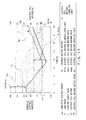
- FIG. 7 is a schematic diagram of a decrement determining method when the leveling target value x is reduced in the power leveling system 1 according to the first embodiment.
- the horizontal axis indicates time and the vertical axis indicates power and electric energy
- FIG. 7 illustrates the fluctuation of the load power Pl in the leveling period T0 with the lapse of time. Assume that the leveling target value x in the leveling period T0 is reduced by the variation dx.
- the electric energy expressed in the area ⁇ is a discharged energy from the electric cell required by decreasing the leveling target value x by the variation dx
- the electric energy expressed in the area ⁇ is the charged energy to the electric cell decreasing by reducing the leveling target value x by the variation dx.
- the electric energy as a sum of the area ⁇ and the area ⁇ corresponds to the excess of the electric cell residue Br which decreases by reducing the leveling target value x by the variation dx.
- the variation dx is determined so that the excess of the electric cell residue Br may corresponds to the product of the variation dx and the leveling period T0.
- the target determination unit 22 determines the variation dx so that the sum of the charged energy which becomes unnecessary and the charged energy which becomes necessary by increasing the leveling target value x by the variation dx corresponds to the deficiency of the electric cell residue Br which increases by increasing the leveling target value x by the variation dx.
- FIGS. 8 and 9 are flowcharts of the operation of the power leveling system 1 according to the first embodiment.
- FIG. 10 is an explanatory view of the state in which the electric cell residue runs out.
- the target determination unit 22 monitors whether or not the leveling period starting time set in S 52 has come by comparing the leveling period starting time stored in the storage unit 24 and acquired present time by the time acquisition unit not illustrated in the attached drawings and (NO in S 53 ). If the leveling period starting time has come (YES in S 53 ), the target determination unit 22 first acquires the electric cell residue B (%) as an initial value of the electric cell residue Br (S 54 ), and starts the leveling control (S 55 ).
- the target determination unit 22 resets the leveling period timer (not illustrated in the attached drawings) (S 61 ). Furthermore, the target determination unit 22 resets the electric cell residue maximum value Bmax to Br, the electric cell residue minimum value Bmin to Br (%), and the electric cell residue initial value B0 to Br (S 62 ), and resets the demand timing timer (not illustrated in the attached drawings) (S 63 ).
- the target determination unit 22 outputs an operation signal for allowing the switch control unit 26 to close the switch 5 and start the reception of power, and the switch 5 closes the connection according to the indication signal from the switch control unit 26 .
- the electric cell 11 detects a normal input and starts or continues the charge of the own electric cell 11 and the supply of power from the power supply 3 to a load (S 64 ).
- the target determination unit 22 resets the cumulative electric energy Ein to 0 (Wh) (S 65 ), and resets the monitor control period timer (not illustrated in the attached drawings) (S 66 ).
- the target determination unit 22 continues monitoring until the expiration of the monitor control period timer (NO in S 67 ). If the timer expires (YES in S 67 ), the target determination unit 22 acquires the electric cell residue Br measured by the electric cell residue measurement unit 12 (S 68 ). The target determination unit 22 compares the acquired electric cell residue Br with the electric cell residue maximum value Bmax. When the electric cell residue Br is not more than the electric cell residue maximum value Bmax, control is passed to step S 71 (YES in S 69 ).
- the target determination unit 22 updates the electric cell residue maximum value Bmax to the electric cell residue Br (S 70 ), stores the result in the storage unit 24 , and control is passed to step S 71 .
- the target determination unit 22 compares the acquired electric cell residue Br with the electric cell residue minimum value Bmin. If the electric cell residue Br is not less than the electric cell residue minimum value Bmin, control is passed to step S 73 (YES in S 71 ).
- the target determination unit 22 updates the electric cell residue minimum value Bmin to the electric cell residue Br (S 72 ), stores the result in the storage unit 24 and control is passed to step S 73 .
- the target determination unit 22 acquires the received power Pin (W) by the received power measurement unit 9 (S 73 ).
- the switch control unit 26 compares the cumulative electric energy Ein calculated in S 81 with the current leveling target value x. If the cumulative electric energy Ein is lower than the leveling target value x (NO in S 82 ), control is passed to step S 84 . If the cumulative electric energy Ein calculated in S 81 is not less than the leveling target value x (YES in S 82 ), then the switch control unit 26 outputs to the switch 5 an operation signal for disconnection, and the switch 5 disconnects the connection. In this case, the electric cell 11 detects the disconnection of an input, and starts or continues the power supply to the load by the discharge (S 83 ).
- the processes in S 66 through S 84 are repeated.
- the target determination unit 22 judges whether or not the condition of the electric cell residue maximum value Bmax ⁇ electric cell residue upper use limit Bu, or the electric cell residue minimum value Bmin ⁇ electric cell residue lower use limit Bl, or the electric cell residue balance Bd ⁇ 0 holds true (S 87 ). If the result of the judgment satisfies the condition, then the target determination unit 22 judges that the leveling target value x is to increase, and passes control to the process in FIG. 11 . If the condition is not satisfied, control is passed to step S 88 .
- the target determination unit 22 judges whether or not the conditions of the electric cell residue maximum value Bmax>electric cell residue upper use limit Bu, and the electric cell residue minimum value Bmin>electric cell residue lower use limit Bl, and the electric cell residue balance Bd>0 hold true (S 88 ). If the result of the judgment satisfies the conditions (YES in S 88 ), the target determination unit 22 judges that the leveling target value x is to decrease, and passes control to the process in FIG. 13 . If the result of the judgment does not satisfy the condition, the target determination unit 22 does not change the leveling target value x, and control is returned to the process in FIG. 8 .
- the target determination unit 22 performs the judging process etc. by storing in or reading from the storage unit 24 the electric cell residue maximum value Bmax, the electric cell residue minimum value Bmin, the electric cell residue initial value B0, etc.
- the condition relating to the above-mentioned reference input elements is defined as follows depending on whether the leveling target value x is to increase or decrease in the next leveling period T0.
- At least one condition each from the above-mentioned 4 decrease and 4 increase conditions is selected.
- a logical sum or a logical product is acquired from them.
- the increase condition for increase of the leveling target value x is prioritized to avoid a power failure, and a logical product is acquired for the decrease condition, and the logical sum is acquired for the increase condition.
- 15 conditions are obtained as the decrease condition, and 15 conditions are obtained as the increase condition.
- Condition 1a Decrease condition: Condition 1a, and condition 1b, and condition 1c (logical product)
- Condition 2a or condition 2b, or condition 2c (logical sum)
- FIG. 11 is a flowchart of the increment determining process of the leveling target value x.
- FIG. 13 is an explanatory view of the increment determining process of the leveling target value x.
- the target determination unit 22 in the increment determining process 100 judges whether or not the following expression holds true (S 91 ).
- electric cell residue lower use limit Bl ⁇ electric cell residue minimum value B min ⁇ 0 ⁇ electric cell residue balance Bd
- FIG. 12 illustrates an example of variations of the received power Pin, the cumulative electric energy Ein, the load power PL, and the electric cell residue Br in the leveling period T0, and also illustrates the electric cell residue allowable lower limit Blim.
- the electric cell residue Br is regarded.
- the electric cell residue allowable lower limit Blim is explained.
- variable load 13 is a load which is not allowed to make an accidental stop like a computer, it is necessary to perform control to monitor the electric cell residue Br, and perform switching control to receive power from the power supply 3 by closing the switch 5 before the electric cell residue runs out.
- the lower limit of the electric cell residue Br for judgment of “no electric cell residue” is not “0”, but is to be the value with a residue taken into account for the demand until the next monitoring time.
- the value is referred to as an electric cell residue allowable lower limit Blim.
- the electric cell residue allowable lower limit Blim is determined as a value of the electric cell residue Br for a product of the monitoring time T2 and the maximum dischargeable power Pmax or the maximum power of the variable load 13 , and a margin ⁇ may be added for guarantee.
- the electric cell residue Br is not more than electric cell residue allowable lower limit Blim, and there is no electric cell residue Br actually.
- a setting is made to charge the electric cell 11 to avoid a power failure when the electric cell residue Br is lower than the electric cell residue lower use limit Bl.
- the electric cell residue Br changes as the expanded electric cell residue Br′ illustrated in FIG. 12 , and is to become the expanded minimum electric cell residue Bl. Therefore, when the variation dx of the leveling target value x is calculated, the value of the electric cell residue Br is not used as is, but it is to be considered that the electric cell residue Br has changed based on the expanded electric cell residue Br′.
- the expanded electric cell residue Br′ is calculated by, for example, subtracting the received electric energy in the period in which the switch 5 is closed for avoiding a power failure from the electric cell residue Br.
- FIG. 13 illustrates an example of variations of the received power Pin, the cumulative electric energy Ein, the load power Pl, and the electric cell residue Br.
- the electric cell residue Br is regarded.
- the target determination unit 22 calculates the minimum value deficiency and the balance deficiency with reference to the electric cell residue Br stored in the storage unit 24 , and judges as the change reference Bx whichever is larger between them as a deficiency of the electric cell residue Br.
- the target determination unit 22 defines the change reference Bx of the electric cell residue Br as 0 ⁇ Bd (S 93 ).
- the target determination unit 22 judges as the change reference Bx for changing the leveling target value x whichever is larger between the minimum value deficiency and the balance deficiency as a deficiency of the electric cell residue Br.
- leveling target increment value (variation dx )( Wh ) 0.01 ⁇ deficiency (%) of electric cell residue Br which decreases by the increase of target value (the change reference Bx ) ⁇ electric cell capacity Bc ( Wh )/leveling period T 0( h ) (equation 2)
- FIG. 14 is a flowchart of the process of determining the decrement of the leveling target value x.
- FIG. 15 is an explanatory view of the process of determining the decrement of the leveling target value x.
- the target determination unit 22 judges whether or not “electric cell residue maximum value Bmax ⁇ electric cell residue upper use limit Bu ⁇ electric cell residue minimum value Bmin ⁇ electric cell residue lower use limit Bl” holds true (S 101 ).
- FIG. 15 the horizontal axis indicates time, the vertical axis indicates the power, the electric energy, and the electric cell residue.
- FIG. 15 illustrates an example of variations of the received power Pin, the cumulative electric energy Ein, the load power Pl, and the electric cell residue Br in the leveling period T0. In this example, the electric cell residue Br is regarded.
- the target determination unit 22 refers to the electric cell residue Br stored in the storage unit 24 , and judges as the change reference Bx for changing the leveling target value x whichever is smaller between the residue excess and the minimum value surplus as an excess of the electric cell residue Br.
- leveling target value (variation dx )( Wh ) 0.01 ⁇ excess (%) of electric cell residue Br which decreases by the decrease of target value (the change reference Bx ) ⁇ electric cell capacity Bc ( Wh )/leveling period T 0( h ) (equation 3)
- the variation dx of the leveling target value x in the next leveling period T0 is calculated based on at least one of the electric cell residue maximum value Bmax in the leveling period T0 the electric cell residue minimum value Bmin, and the electric cell residue balance Bd, thereby changing the leveling target value x in the next leveling period T0.
- the leveling target value x is changed so that the sum of the charged energy and the discharged energy of the electric cell 11 which change by changing the leveling target value x may be equal to the electric energy which changes by changing the leveling target value x.
- the power leveling system 1 may perform the leveling control appropriate for the status of the variable load 13 .
- the leveling target value x appropriate for the situation of the power supply 3 and the variable load 13 may easily obtained in the next leveling period T0. Therefore, the peak of the received power Pin may be reduced, and the rise of the received power due to the residue deficiency of the electric cell 11 and the failure to reserve the necessary electric cell residue Br by the end of the leveling period T0 may be avoided. Therefore, the degradation of the leveling effect by the residue excess or deficiency of the electric cell 11 may be prevented, thereby realizing the power leveling system 1 as a system of a high leveling effect.
- the electric cell residue maximum value Bmax and the electric cell residue minimum value Bmin in the leveling period T0 may be updated each time the electric cell residue Br is acquired so that it is not necessary to include a storage unit having a large storage capacity to store all electric cell residue Br in the power leveling system.
- the present variation example is related to a method for determining the variation dx of the leveling target value x according to the first embodiment. Therefore, the configuration of the power leveling system 1 and the processes in FIGS. 8 through 11 until the judgment of the increment or decrement of the leveling target value x are the same as in the present embodiment.
- FIG. 16 is a flowchart illustrating an increment determining process.
- the target determination unit 22 determines the change reference Bx by the following equation 4 (S 111 ).
- Bx max(min(max(100 ⁇ B max, Bl ), Bl ⁇ B min), ⁇ Bd ) (equation 4)
- the change reference Bx is determined by the following logics.
- Bl ⁇ Bmin is a negative value
- the surplus if any when the electric cell residue maximum value Bmax is low and the surplus for charge remains may be compensation.
- FIG. 17 is an explanatory view of (3) above in the process of determining the increment of the leveling target value x.
- the horizontal axis indicates time, and the vertical axis indicates the power, the electric energy, and the electric cell residue.
- FIG. 17 is an example of variations of the received power Pin, the cumulative electric energy Ein, the load power Pl, and the electric cell residue Br in the leveling period T0. In this case, the electric cell residue Br is regarded.
- the electric cell residue minimum value Bmin the minimum value of the expanded electric cell residue Br′ described above with reference to FIG. 12 is used,
- defined as the change reference Bx is the value whichever is the largest among (electric cell residue decrement: ⁇ Bd), (difference between the electric cell capacity Bc and the electric cell residue maximum value: 100 ⁇ Bmin), and (electric cell residue lower use limit: Bl). If the deficiency of the electric cell residue minimum value Bmin below the lower use limit is not compensated for as is, the largest value among the values above determines the deficiency.
- FIG. 18 is an explanatory view of (4) above in the process for determining the increment of the leveling target value x.
- the horizontal axis indicates time, and the vertical axis indicates the power, the electric energy, and the electric cell residue.
- FIG. 18 illustrates an example of variations of the received power Pin, the cumulative electric energy Ein, the load power Pl, and the electric cell residue Br in the leveling period T0. In this example, the electric cell residue Br is regarded.
- FIG. 18 illustrates the minimum value deficiency: Bl ⁇ Bmin, the balance deficiency: 0 ⁇ Bd and the difference between the electric cell capacity Bc and the electric cell residue maximum value: 100 ⁇ Bmax, and the electric cell residue lower use limit: Bl in the judgment in S 111 in FIG. 16 .
- the target determination unit 22 performs of these values a calculation with reference to the electric cell residue Br stored in the storage unit 24 at the end of the leveling period T0. That is, the target determination unit 22 judges what is the largest in the minimum value deficiency, the difference between the electric cell capacity and the electric cell residue maximum value, and the electric cell residue lower use limit as the deficiency of the electric cell residue as the change reference Bx for changing the leveling target value x. In this case, it is assumed that as the electric cell residue minimum value Bmin, the minimum value of the expanded electric cell residue Br′ explained above with reference to FIG. 12 . is used.
- the electric cell residue decrement ( ⁇ Bd) is the deficiency independent of whether or not the electric cell residue minimum value Bmin is a negative value, it is use as a candidate as is.
- the difference 100 ⁇ Bmax between the electric cell capacity and the electric cell maximum residue value refers to the electric cell capacity which has not been used up, and is a candidate for a surplus of the chargeable power.
- the electric cell residue lower use limit Bl is the value by which the minimum value of the actual electric cell residue Br (not the expanded electric cell residue Br′) is lower than the lower use limit, and is used as a candidate to reserve the electric energy for the lower use limit.
- the logic above is expressed by the equation 4 above.
- FIG. 19 is a flowchart of a decrement determining process 130 .
- the target determination unit 22 defines the change reference Bx by the following equation 5 (S 121 ).
- Bx min( B max ⁇ Bu,B min ⁇ Bl ) (equation 5)
- the equation 5 is similar to the processes in S 101 through S 103 in the decrement determining process 110 according to the first embodiment.
- the variation dx of the leveling target value x in the next leveling period T0 is calculated based on at least one of the electric cell residue maximum value Bmax, the electric cell residue minimum value Bmin, the in the present leveling period T0 electric cell balance Bd, and the electric cell residue lower use limit Bl, and the leveling target value x in the next leveling period T0 is changed.
- the target determination unit 22 increases the leveling target value x by calculating the change reference Bx by the equation 4.
- the target determination unit 22 decreases the leveling target value x by calculating the change reference Bx by the equation 5.
- the leveling target value x is changed so that the sum of the charged energy and the discharged energy of the electric cell 11 which change by changing the leveling target value x may be equal to the electric energy which changes by changing the leveling target value x.
- the power leveling system 1 may perform the leveling control appropriate for the status of the variable load 13 .
- the leveling target value x appropriate for the situation of the power supply 3 and the variable load 13 may easily obtained in the next leveling period T0. Therefore, the peak of the received power Pin may be reduced, and the rise of the received power due to the residue deficiency of the electric cell 11 and the failure to reserve the necessary electric cell residue Br by the end of the leveling period T0 may be avoided. Therefore, the degradation of the leveling effect by the residue excess or deficiency of the electric cell 11 may be prevented, thereby realizing the power leveling system 1 as a system of a high leveling effect.
- the power leveling system according to the second embodiment is described below with reference to FIGS. 20 through 25 .
- the configuration and operation similar to those according to the first embodiment are assigned the same reference numerals and the overlapping explanation is avoided.
- the second embodiment is a variation example of a method for determining the variation dx of the leveling target value x according to the first embodiment. Therefore, the configuration (Fcg, 1) of the power leveling system 1 and the process in FIG. 8 are the same as in the present embodiment.
- FIG. 20 illustrates the process performed after the process in FIG. 8 .
- the target determination unit 22 resets the leveling period timer (not illustrated in the attached drawings) (S 161 ).
- the target determination unit 22 resets the demand timing timer (not illustrated in the attached drawings) (S 163 ).
- the target determination unit 22 outputs to the switch control unit 26 the operation signal to close the switch 5 and start the reception of power, and the switch 5 closes the connection at the instruction signal from the switch control unit 26 .
- the electric cell 11 detects a normal input, and starts or continues the charging to own electric cell 11 and the supply of power from the power supply 3 to the load (S 164 ).
- the target determination unit 22 resets the cumulative electric energy Ein to 0 (Wh) (S 165 ), and also resets the monitor control period timer (not illustrated in the attached drawings) (S 166 ).
- the target determination unit 22 performs monitoring until the monitor control period timer expires (NO in S 167 ). If it expires (YES in S 167 ), the target determination unit 22 acquires the electric cell residue Br measured by the electric cell residue measurement unit 12 , and stores it in the storage unit 24 (S 168 ). The target determination unit 22 compares the acquired electric cell residue Br with the electric cell residue maximum value Bmax. When the electric cell residue Br is not more than the electric cell residue maximum value Bmax, control is passed to step S 71 (YES in S 169 ).
- the target determination unit 22 updates the electric cell residue maximum value Bmax to the electric cell residue Br (S 170 ), stores it in the storage unit 24 , and passes control to S 171 .
- the target determination unit 22 compares the acquired electric cell residue Br with the electric cell residue minimum value Bmin. If the electric cell residue Br is not less than the electric cell residue minimum value Bmin, then control is passed to S 173 (YES in S 171 ). When the electric cell residue Br is smaller than the electric cell residue minimum value Bmin (NO in S 171 ), then the target determination unit 22 updates the electric cell residue minimum value Bmin to the electric cell residue Br (S 172 ), stores it in the storage unit 24 , and passes control to S 173 . The target determination unit 22 acquires the received power Pin (W) by the received power measurement unit 9 (S 173 ).
- the switch control unit 26 compares the cumulative electric energy Ein calculated in S 181 with the current leveling target value x. If the cumulative electric energy Ein is lower than the leveling target value x (NO in S 184 ), then control is passed to S 186 . If the cumulative electric energy Ein calculated in S 181 is not less than the leveling target value x (YES in S 182 ), the switch control unit 26 outputs to the switch 5 the operation signal for disconnection, and the switch 5 shuts off the connection. In this case, the electric cell detects the disconnection of input, and starts or continues the supply of power to the load by the discharge (S 183 ).
- the target determination unit 22 judges whether or not the condition of the electric cell residue maximum value Bmax ⁇ the electric cell residue upper use limit Bu, or the electric cell residue minimum value Bmin ⁇ electric cell residue lower use limit Bl, or the electric cell residue balance Bd ⁇ 0 is satisfied (S 189 ). If the result of the judgment is a matching result, control is passed to FIG. 22 (YES in S 189 ). If the result of the judgment is a non-matching result, control is passed to S 190 (NO in S 189 ).
- the target determination unit 22 judges whether or not the conditions of the electric cell residue maximum value Bmax>the electric cell residue upper use limit Bu, and the electric cell residue minimum value Bmin>electric cell residue lower use limit Bl, and the electric cell residue balance Bd>0 are satisfied (S 190 ). If the result of the judgment is a matching result, then control is passed to FIG. 24 . If the result is a non-matching result, control is returned to FIG. 20 .
- FIG. 22 is an explanatory view of the increment determining process.
- the processes in S 111 through S 113 are the same as the processes in S 111 through S 113 in FIG. 16 . That is, as illustrated in FIG. 22 , the target determination unit 22 determines the change reference Bx by the equation 4 above (S 111 ).
- the target determination unit 22 judges whether or not the cumulative electric energy maximum value Emax is not less than the leveling target value x (S 114 ). If Emax x holds true (YES in S 114 ), then the target determination unit 22 sets the leveling target value x as the cumulative electric energy maximum value Emax (S 115 ), and returns control to the process in FIG. 8 . If Emax ⁇ x does not hold true (NO in S 114 ), then control is returned to the process in FIG. 8 .
- FIG. 23 illustrates an example of variations of the cumulative electric energy Ein, the load power Pl, and the electric cell residue Br in the two consecutive leveling periods T0.
- the horizontal axis indicates time
- the vertical axis indicates power, electric energy, and electric cell residue.
- the cumulative electric energy Ein and the electric cell residue Br are regarded.
- the target determination unit 22 calculates the change reference Bx by the equation 4 with reference to the electric cell residue Br stored in the storage unit 24 .
- a demand contract for determining the basic fee as a 1-subsequent-year contract electric energy may be made based on the cumulative electric energy maximum value Emax for the cumulative electric energy Ein of the previous day.
- the applicable value may be determined by the following equation 6 not to exceed the cumulative electric energy maximum value Emax of the previous day.
- Next leveling target value ( x+dx ) cumulative electric energy maximum value E max of the present round ⁇ cumulative electric energy maximum value E max ⁇ monitoring time T 2/demand timing T 1 (equation 6)
- the peak of the cumulative electric energy Ein may be suppressed, thereby preventing the cumulative electric energy maximum value Emax of the previous round from being exceeded.
- FIG. 24 is a flowchart of a decrement determining process of the leveling target value x.
- FIG. 25 is an explanatory view of the decrement determining process of the leveling target value x.
- the target determination unit 22 determines the change reference Bx by the equation 5 above (S 121 ).
- FIG. 25 illustrates an example of variations of the cumulative electric energy Ein, the load power Pl, and the electric cell residue Br.
- the electric cell residue Br is regarded.
- the fully charged state is constantly maintained throughout the leveling period T0. That is, the charge-discharge process has not occurred in the leveling period T0, and the amount of excess is not estimated only from the electric cell residue Br. There is the possibility that the charge-discharge process does not occur even when the leveling target value x is excessively large.
- the target determination unit 22 sets the leveling target value x of the next leveling period T0 as the value of the cumulative electric energy maximum value Emax of the leveling period T0 immediately before.
- an applied value may be calculated by the following equation 7.
- Next leveling target value ( x ⁇ dx ) current cumulative electric energy maximum value E max ⁇ current cumulative electric energy maximum value E max ⁇ monitoring time T 2/demand timing T 1 (equation 7)
- the target determination unit 22 may detect the discharge of the electric cell 11 based on the state of the switch 5 , and store the discharge result in the storage unit 24 . Furthermore, the target determination unit 22 may store the received power Pin in the storage unit 24 , calculate the peak value CF based on the received power Pin stored in the storage unit 24 , and judge the presence/absence of the discharge.
- the variation dx of the leveling target value x in the next leveling period T0 is calculated based on at least one of the electric cell residue maximum value Bmax, the electric cell residue minimum value Bmin, and the electric cell residue balance Bd in the leveling period T0, and the leveling target value x in the next leveling period T0 is changed.
- the leveling target value x is changed so that the sum of the charged energy and the discharged energy of the electric cell 11 which change by changing the leveling target value x may be equal to the electric energy which changes by changing the leveling target value x.
- the power leveling system 1 may perform the leveling control appropriate for the status of the variable load 13 .
- the leveling target value x appropriate for the situation of the power supply 3 and the variable load 13 may easily obtained in the next leveling period T0. Therefore, the peak of the received power Pin may be reduced, and the rise of the received power due to the residue deficiency of the electric cell 11 and the failure to reserve the necessary electric cell residue Br by the end of the leveling period T0 may be avoided. Therefore, the degradation of the leveling effect by the residue excess or deficiency of the electric cell 11 may be prevented, thereby realizing the power leveling system 1 as a system of a high leveling effect.
- next leveling target value x+dx to be increased by the method shove is compared with the current cumulative electric energy maximum value Emax.
- the cumulative electric energy maximum value Emax is larger, the next leveling target value x is set as a value based on the cumulative electric energy maximum value Emax.
- the variation dx is determined by referring to the cumulative electric energy maximum value Emax as the value representing the transition of the cumulative electric energy Ein, thereby preventing the occurrence of the peak electric energy which exceeds the current cumulative electric energy maximum value Emax in the next leveling period T0.
- the variation dx for the next leveling target value which is reduced by the method above is compared with the difference between the current cumulative electric energy maximum value Emax and the leveling target value x, and whichever is larger is defined as the variation dx.
- the variation dx is determined by referring to the cumulative electric energy maximum value Emax and the cumulative electric energy minimum value Emin which are the values representing the transition of the cumulative electric energy Ein.
- a leveling target value appropriate for the power facilities and the power usage situation of a load may be determined. That is, a leveling control device and a leveling control method with a higher peak reduction effect may be provided.
- the target determination unit 22 is an example of an electric cell residue acquisition unit, a target determination unit, and a power calculation unit
- the storage unit 24 is an example of a storage device.
- FIG. 26 is a block diagram of an example of the hardware configuration of a standard computer.
- a computer 300 is connected to a central processing unit (CPU) 302 , memory 304 , an input device 306 , an output device 308 , an external storage device 312 , a medium drive device 314 , a network connection device 318 , etc. through a bus 310 .
- CPU central processing unit
- the CPU 302 is an operation device for controlling the operation of the entire computer 300 .
- the memory 304 is a storage unit for storing a program in advance, and for use as a work area as necessary when the program is executed.
- the memory 304 is, for example, random access memory (RAM), read only memory (ROM), etc.
- the input device 306 acquires an input of various types of information from a user of a computer associated with operation contents when the user operates the input device 306 , and transmits the acquired input information to the CPU 302 .
- the input device 306 may be, for example, a keyboard device, a mouse device, etc.
- the output device 308 outputs a result of the process performed by the computer 300 , and includes a display device etc. For example, a display device displays a text and an image depending on the display data transmitted by the CPU 302 .
- the external storage device 312 is, for example, a storage device such as a hard disk etc., and stores various types of control programs executed by the CPU 302 , acquired data, etc.
- the medium drive device 314 performs a write and a read to and from a portable recording medium 316 .
- the CPU 302 may be designed to perform various types of controlling processes by reading a specified control program stored in the portable recording medium 316 through the recording medium drive device 314 .
- the portable recording medium 316 is, for example, a compact disc (CD)-ROM, a digital versatile disc (DVD), universal serial bus (USB) memory, etc.
- the network connection device 318 is an interface device for managing communications of various types of data performed by a cable or wireless with an external unit.
- the bus 310 connects each of the above-mentioned devices and functions as a communication path for communicating data.
- the program for directing the computer 300 to perform leveling control according to the above-mentioned first embodiment and its variation examples, and the second embodiment is stored in, for example, the external storage device 312 .
- the CPU 302 reads the program from the external storage device 312 , and performs an operation of power leveling control.
- a control program for directing the CPU 302 to perform the process of leveling control is first generated and stored in the external storage device 312 .
- a specified instruction is transmitted from the input device 306 to the CPU 302 , and the control program is read from the external storage device 312 for execution.
- the program may be stored in the portable recording medium 316 .
- the present invention is not limited to the above-mentioned embodiments, but may be configured or embodied within the scope of the gist of the present invention.
- determination of the variation dx of the leveling target value x is not limited to the determining method according to the first embodiment and its variation example, and the second embodiment.
- the variation dx determined based on a value representing the transition of the electric cell residue Br may be determined based on at least one of, for example, the maximum value, the minimum value, and the difference between the first and last values.
- the power which is referred to when the variation dx is determined is explained above using an example of referring to the cumulative electric energy Ein obtained by accumulating received power from the power supply 3 , but the value obtained by averaging the received power Pin from the power supply 3 per specified time may be used. Furthermore, the value obtained by averaging the power consumption of the variable load 13 per specified time, or the electric energy accumulated for a specified time period may be referred to.
- the combinations used for determination of the variation dx increment and decrement are not limited to the combinations explained in the above-mentioned first embodiment and its variation example, and the second embodiment, but any combinations are acceptable.
- the determining method explained in the first embodiment may be applied to other variation examples or embodiments.
- the leveling control unit 20 may be realized as hardware such as a microcontroller.
Landscapes
- Engineering & Computer Science (AREA)
- Power Engineering (AREA)
- Supply And Distribution Of Alternating Current (AREA)
- Charge And Discharge Circuits For Batteries Or The Like (AREA)
Applications Claiming Priority (1)
| Application Number | Priority Date | Filing Date | Title |
|---|---|---|---|
| PCT/JP2011/068992 WO2013027272A1 (ja) | 2011-08-23 | 2011-08-23 | 電力平準化制御装置および電力平準化制御方法 |
Related Parent Applications (1)
| Application Number | Title | Priority Date | Filing Date |
|---|---|---|---|
| PCT/JP2011/068992 Continuation WO2013027272A1 (ja) | 2011-08-23 | 2011-08-23 | 電力平準化制御装置および電力平準化制御方法 |
Publications (2)
| Publication Number | Publication Date |
|---|---|
| US20140132071A1 US20140132071A1 (en) | 2014-05-15 |
| US9502916B2 true US9502916B2 (en) | 2016-11-22 |
Family
ID=47746054
Family Applications (1)
| Application Number | Title | Priority Date | Filing Date |
|---|---|---|---|
| US14/158,947 Expired - Fee Related US9502916B2 (en) | 2011-08-23 | 2014-01-20 | Power leveling control device and power leveling control method |
Country Status (4)
| Country | Link |
|---|---|
| US (1) | US9502916B2 (ja) |
| JP (1) | JP5737409B2 (ja) |
| CN (1) | CN103733459B (ja) |
| WO (1) | WO2013027272A1 (ja) |
Cited By (1)
| Publication number | Priority date | Publication date | Assignee | Title |
|---|---|---|---|---|
| US20220407329A1 (en) * | 2021-06-16 | 2022-12-22 | Hewlett-Packard Development Company, L.P. | Battery charge regulation |
Families Citing this family (12)
| Publication number | Priority date | Publication date | Assignee | Title |
|---|---|---|---|---|
| JP6017017B2 (ja) * | 2013-03-11 | 2016-10-26 | 三菱電機株式会社 | 車両電力管理装置 |
| JP5995804B2 (ja) * | 2013-08-09 | 2016-09-21 | 三菱重工業株式会社 | 蓄電システムの管理装置及び制御目標値決定方法 |
| CN104620457B (zh) * | 2013-09-11 | 2017-09-26 | 株式会社东芝 | 蓄电控制装置 |
| US9629104B2 (en) | 2013-11-27 | 2017-04-18 | At&T Intellectual Property I, Lp | Client-side scheduling for media transmissions according to client device states |
| JP6624416B2 (ja) * | 2014-09-11 | 2019-12-25 | 清水建設株式会社 | 需要電力の目標値算出方法及び目標値算出装置 |
| US10095298B2 (en) | 2015-03-27 | 2018-10-09 | Nec Corporation | Control device |
| JP6048527B2 (ja) * | 2015-03-27 | 2016-12-21 | 日本電気株式会社 | 制御装置 |
| JP5943114B1 (ja) | 2015-03-27 | 2016-06-29 | 日本電気株式会社 | 制御装置 |
| JP6485172B2 (ja) * | 2015-04-01 | 2019-03-20 | 富士電機株式会社 | 充放電期間設定装置、充放電期間設定プログラム、および充放電期間設定方法 |
| JP2018113829A (ja) * | 2017-01-13 | 2018-07-19 | 三菱電機株式会社 | 蓄電制御装置 |
| JP6796536B2 (ja) * | 2017-04-04 | 2020-12-09 | 株式会社Nttドコモ | 電源システム |
| CN114268172B (zh) * | 2021-12-02 | 2022-09-30 | 国网江苏省电力有限公司镇江供电分公司 | 一种多类型储能运营控制方法 |
Citations (10)
| Publication number | Priority date | Publication date | Assignee | Title |
|---|---|---|---|---|
| JPH1141831A (ja) | 1997-07-11 | 1999-02-12 | N T T Facilities:Kk | 電力貯蔵装置、及び電力貯蔵装置の運転方法 |
| JP2002017044A (ja) | 2000-06-30 | 2002-01-18 | Kansai Electric Power Co Inc:The | 電力変動平滑化装置及びそれを備えた分散電源システムの制御方法 |
| JP2003299247A (ja) | 2002-03-29 | 2003-10-17 | Ntt Power & Building Facilities Inc | 交流電源供給システム |
| JP2009213319A (ja) | 2008-03-06 | 2009-09-17 | Toshiba Corp | 自然エネルギー発電装置の出力変動抑制装置 |
| US20110089905A1 (en) * | 2009-10-16 | 2011-04-21 | Junya Yano | Power supply device |
| US8219259B2 (en) * | 2009-06-03 | 2012-07-10 | International Business Machines Corporation | Maintaining uniform power consumption from an electric utility by a local load in a power distribution system |
| US20140015469A1 (en) * | 2010-03-11 | 2014-01-16 | Virgil L. Beaston | Battery Management System For A Distributed Energy Storage System, and Applications Thereof |
| US8779724B2 (en) * | 2009-12-28 | 2014-07-15 | Toyota Jidosha Kabushiki Kaisha | Residential electric power storage system |
| US8854004B2 (en) * | 2011-01-12 | 2014-10-07 | Samsung Sdi Co., Ltd. | Energy storage system and controlling method thereof |
| US9071068B2 (en) * | 2010-06-30 | 2015-06-30 | Panasonic Intellectual Property Management Co., Ltd. | Charge/discharge control apparatus |
Family Cites Families (3)
| Publication number | Priority date | Publication date | Assignee | Title |
|---|---|---|---|---|
| JP2001327080A (ja) * | 2000-05-10 | 2001-11-22 | Kansai Electric Power Co Inc:The | 電力貯蔵装置及びそれを備えた分散電源システムの制御方法 |
| JP4969229B2 (ja) * | 2006-12-18 | 2012-07-04 | 三菱重工業株式会社 | 電力貯蔵装置及びハイブリッド型分散電源システム |
| CN102104251B (zh) * | 2011-02-24 | 2013-04-24 | 浙江大学 | 一种并网运行模式下的微电网实时能量优化调度方法 |
-
2011
- 2011-08-23 WO PCT/JP2011/068992 patent/WO2013027272A1/ja active Application Filing
- 2011-08-23 CN CN201180072834.8A patent/CN103733459B/zh not_active Expired - Fee Related
- 2011-08-23 JP JP2013529809A patent/JP5737409B2/ja not_active Expired - Fee Related
-
2014
- 2014-01-20 US US14/158,947 patent/US9502916B2/en not_active Expired - Fee Related
Patent Citations (10)
| Publication number | Priority date | Publication date | Assignee | Title |
|---|---|---|---|---|
| JPH1141831A (ja) | 1997-07-11 | 1999-02-12 | N T T Facilities:Kk | 電力貯蔵装置、及び電力貯蔵装置の運転方法 |
| JP2002017044A (ja) | 2000-06-30 | 2002-01-18 | Kansai Electric Power Co Inc:The | 電力変動平滑化装置及びそれを備えた分散電源システムの制御方法 |
| JP2003299247A (ja) | 2002-03-29 | 2003-10-17 | Ntt Power & Building Facilities Inc | 交流電源供給システム |
| JP2009213319A (ja) | 2008-03-06 | 2009-09-17 | Toshiba Corp | 自然エネルギー発電装置の出力変動抑制装置 |
| US8219259B2 (en) * | 2009-06-03 | 2012-07-10 | International Business Machines Corporation | Maintaining uniform power consumption from an electric utility by a local load in a power distribution system |
| US20110089905A1 (en) * | 2009-10-16 | 2011-04-21 | Junya Yano | Power supply device |
| US8779724B2 (en) * | 2009-12-28 | 2014-07-15 | Toyota Jidosha Kabushiki Kaisha | Residential electric power storage system |
| US20140015469A1 (en) * | 2010-03-11 | 2014-01-16 | Virgil L. Beaston | Battery Management System For A Distributed Energy Storage System, and Applications Thereof |
| US9071068B2 (en) * | 2010-06-30 | 2015-06-30 | Panasonic Intellectual Property Management Co., Ltd. | Charge/discharge control apparatus |
| US8854004B2 (en) * | 2011-01-12 | 2014-10-07 | Samsung Sdi Co., Ltd. | Energy storage system and controlling method thereof |
Non-Patent Citations (2)
| Title |
|---|
| International Search Report, mailed in connection with PCT/JP2011/068992 and mailed Dec. 13, 2011. |
| Notification of Transmittal of Translation of the International Preliminary Report on Patentability (Form PCT/IB/338, Form PCT/IB/373 & Form PCT/ISA/237), PCT/JP2011/068992, 6 pages, dated Mar. 6, 2014. |
Cited By (1)
| Publication number | Priority date | Publication date | Assignee | Title |
|---|---|---|---|---|
| US20220407329A1 (en) * | 2021-06-16 | 2022-12-22 | Hewlett-Packard Development Company, L.P. | Battery charge regulation |
Also Published As
| Publication number | Publication date |
|---|---|
| WO2013027272A1 (ja) | 2013-02-28 |
| CN103733459B (zh) | 2016-04-06 |
| JP5737409B2 (ja) | 2015-06-17 |
| CN103733459A (zh) | 2014-04-16 |
| JPWO2013027272A1 (ja) | 2015-03-05 |
| US20140132071A1 (en) | 2014-05-15 |
Similar Documents
| Publication | Publication Date | Title |
|---|---|---|
| US9502916B2 (en) | Power leveling control device and power leveling control method | |
| JP5664763B2 (ja) | 電力平準化制御装置、電力平準化蓄電装置、電力平準化制御方法、及び平準化プログラム | |
| US9054556B2 (en) | Power supply device and method of controlling the same | |
| US20140159658A1 (en) | Random Restart Apparatus and Method for Electric Vehicle Service Equipment | |
| CN104466994A (zh) | 通信电源错峰储能系统 | |
| US9488695B2 (en) | Method and apparatus for indicating a low battery level | |
| US20160172899A1 (en) | Operation schedule generating apparatus, operation schedule generating method, and storage battery system | |
| JP5483588B2 (ja) | 充電制御装置 | |
| JP2021507666A (ja) | 休止にされたままの電池の充電状態を管理するための方法 | |
| US20140297055A1 (en) | Power leveling control device and power leveling control method | |
| CN113224813B (zh) | 离网光伏储能系统控制方法、装置、计算机及存储介质 | |
| JP5533343B2 (ja) | 電力平準化システム | |
| US20180013305A1 (en) | Power management apparatus, power management system, and power management method | |
| WO2024066910A1 (zh) | 通信站及其电源控制方法、装置及计算机存储介质 | |
| US20150194827A1 (en) | Information processing device including battery and charging method of battery | |
| KR101736717B1 (ko) | 에너지 저장 장치 및 그의 제어 방법 | |
| JP2019047612A (ja) | 太陽光発電装置および太陽光発電装置の制御方法 | |
| JP5587941B2 (ja) | 無停電電源装置及び無停電電源供給方法 | |
| JP2012161208A (ja) | 電源装置、及び電源制御方法 | |
| JP6394817B2 (ja) | 電源システムおよび該システムにおけるパワーアシスト開始点の再設定方法 | |
| WO2023042456A1 (ja) | 電池容量推定装置、充電計画生成装置、放電計画生成装置及び電池容量推定方法 | |
| CN116094012B (zh) | 供电系统调度方法及相关设备 | |
| US8990603B2 (en) | Image forming apparatus and image forming method for reducing deterioration of a secondary battery | |
| CN114928139A (zh) | 一种锂电池充电方法、系统、装置及计算机可读存储介质 | |
| US20220069590A1 (en) | Standby power supply device and method for charging secondary battery |
Legal Events
| Date | Code | Title | Description |
|---|---|---|---|
| AS | Assignment |
Owner name: FUJITSU LIMITED, JAPAN Free format text: ASSIGNMENT OF ASSIGNORS INTEREST;ASSIGNORS:FUNAKUBO, TOSHIAKI;ENDO, YASUHIRO;SIGNING DATES FROM 20131212 TO 20131213;REEL/FRAME:032305/0001 |
|
| STCF | Information on status: patent grant |
Free format text: PATENTED CASE |
|
| FEPP | Fee payment procedure |
Free format text: MAINTENANCE FEE REMINDER MAILED (ORIGINAL EVENT CODE: REM.); ENTITY STATUS OF PATENT OWNER: LARGE ENTITY |
|
| LAPS | Lapse for failure to pay maintenance fees |
Free format text: PATENT EXPIRED FOR FAILURE TO PAY MAINTENANCE FEES (ORIGINAL EVENT CODE: EXP.); ENTITY STATUS OF PATENT OWNER: LARGE ENTITY |
|
| STCH | Information on status: patent discontinuation |
Free format text: PATENT EXPIRED DUE TO NONPAYMENT OF MAINTENANCE FEES UNDER 37 CFR 1.362 |
|
| FP | Lapsed due to failure to pay maintenance fee |
Effective date: 20201122 |