US949584A - Safety-razor. - Google Patents
Safety-razor. Download PDFInfo
- Publication number
- US949584A US949584A US32270306A US1906322703A US949584A US 949584 A US949584 A US 949584A US 32270306 A US32270306 A US 32270306A US 1906322703 A US1906322703 A US 1906322703A US 949584 A US949584 A US 949584A
- Authority
- US
- United States
- Prior art keywords
- blade
- razor
- base plate
- safety
- represented
- Prior art date
- Legal status (The legal status is an assumption and is not a legal conclusion. Google has not performed a legal analysis and makes no representation as to the accuracy of the status listed.)
- Expired - Lifetime
Links
- 229910000831 Steel Inorganic materials 0.000 description 3
- 239000010959 steel Substances 0.000 description 3
- 244000052616 bacterial pathogen Species 0.000 description 1
- 239000002184 metal Substances 0.000 description 1
- 230000000284 resting effect Effects 0.000 description 1
Images

Classifications
-
- B—PERFORMING OPERATIONS; TRANSPORTING
- B26—HAND CUTTING TOOLS; CUTTING; SEVERING
- B26B—HAND-HELD CUTTING TOOLS NOT OTHERWISE PROVIDED FOR
- B26B21/00—Razors of the open or knife type; Safety razors or other shaving implements of the planing type; Hair-trimming devices involving a razor-blade; Equipment therefor
- B26B21/40—Details or accessories
- B26B21/44—Means integral with, or attached to, the razor for storing shaving-cream, styptic, or the like
- B26B21/446—Shaving aid stored in the razor handle
Definitions
- VVE/V TOR rare CHRISTOPHER W. LEVAIJLEY, .OF MILWAUKEE, WISCONSIN.
- My invention relates to safety razors and hasfor its object to produce a razor of this character, the parts of which may be easily separated so as to be conveniently carried in the pocket or packed in a case.
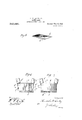
- Figure 1 represents a perspective view of my improved razor.
- Fig. 2 is a plan view of the base plate.
- Fig. 3 is a bottom plan view of the razor blade.
- Fig. 4 is a central transverse sectional view of the razor.
- Fig. 5 is a perspective View of a razor blade of a different form from that shown in Fig. 3.
- Fig. 6 is a plan view of a base plate or support for the razor blade different from that shown in the figures already described.
- Fig. '7 is a view similar to Fig. 6 with a razor blade in place.
- Fig. 8 is a transverse sectional view of a base plate or support for the razor blade.
- Fig. 9 is a' perspective View of still a different form of razor blade.
- Fig. 10 is a transverse sectional view of the blade shown in Fig. 9.
- A indicates the razor handle and 2 a base plate or supporting member for the blade 6.
- the base plate is provided alon its front edge with a series of teeth 3, which operate as a guard for the cutting edge of the blade, as is common in safety razors.
- clasping members may be integral with a supporting plate 20 to which the handle A is connected, as represented Figs. 1 and 4, in which case the razor blade and the base plate 2 are slipped thereunder from the base plate 2, as shown at 4--'4'-, and arranged to swing in planes parallel to the base plate, as represented in 6 and 7.
- the razor blade is formed 0 w or paper steel, that is steel of high grade but very thin, and is arranged to rest upon .77 in the base plate, and to front; or, they may be pivoted to the under side of theafer steel,
- the base plate 'or blade-supporting member 2 with its edge over the toothed or comb edge thereof where it is clamped in position by the clasps 4;.
- the blade 6 is provided with the usual cutting edge 6', or, if desiredavith two such edges, as represented in Fig. 5.
- I may, however, provide it with a stiffening piece of metal '6 along its rear edge, this being usually accomplished by folding the said edge back upon itself, as shown in Figs. 9 and 10.
- fittin depressions and projections may be varie For instance a pair of each, as represented in Figs. 2 and 3, would probably suflioe, though I prefer the arrangement shown in Fig. 5.
- the base plate 2 is represented as being provided at 1ts opposite edges with projectlons 10, 10, adapted to enter recesses formed at the edge of the blade, as represented in Fig. 7, thus properly positioning and holding the blade.
- I provide the blade support ng parts with a flange 2". I have also found 1t of advantage to form the base plate 2 with cut-away ends, as represented at 2'2, to facilitate the handling of can then be removed or put in place while held by its ends. I I
- the handle is screwed into a socket or recess formed in the supporting late 20,
- the base plate an e handle, and arranged to be;clamped in position-by the latter.
- alather receptacle 19 having a depending por- The arrangement of these interthe blade, which parts of my razor may be taken.apart, by
- What I claim is z 1.
- a safety razor the combination of a supporting plate, a handle secured thereto, a base .plate adapted to rest upon the supporting plate and provided along one edge with guard teeth, a blade resting on the base plate, and clasping members at the edges of the supporting plate arranged to secure the plate, the handle, supporting plate,
- the razor may be disassembled and its parts packed in small compass.
- a safety razor the combination with a supporting plate carrying clamping members, of a separable base plate and a razor blade adapted to rest upon the base plate and having interlocking engagement therewith whereby it is held from shifting thereon, the base plate and blade being adapted to be together applied to the supporting blade and held by the'clamping members or to be removed therefrom.
- a safety razor the combination of a support for the blade having clamping members and a guard along its .front edge a handle adapted to be applied to the support but easily separable therefrom, and'a lather receptacle having apart adapted to be clamped between the handle and the base when these are united, and provided with a depending portion adapted to catch the lather, arranged below the guard.
Landscapes
- Life Sciences & Earth Sciences (AREA)
- Forests & Forestry (AREA)
- Engineering & Computer Science (AREA)
- Mechanical Engineering (AREA)
- Details Of Rigid Or Semi-Rigid Containers (AREA)
Description
v By
U. W. LEVALLEY.
SAFETY RAZOR.
APPLICATION FILED JUNE 21, 1906.
949,584. Patented Feb. 15,1910.
2 SHEETS-SHEET 1.
Z x i [/VVE/V TOR O. W. LEVALLEY.
SAFETY RAZOR.
APPLICATION FILED JUNE 21, 1906 Patented Feb. 15, 1910.
949,58&.
2 SHEETSSHEET 2.
[/VVE/V TOR [rare CHRISTOPHER W. LEVAIJLEY, .OF MILWAUKEE, WISCONSIN.
SAFETY-RAZOR.
.Application filed June 21, 1906. Serial No. 322,703.
Specification of Letters Patent.
Patented Feb. 15, 191%.
Tooll whom it may concern:
Be it known that I, CHRISTOPHER W. LE- VALLEY, a citizen of the United States, residing at Milwaukee, in thecounty of Milwaukee and State of Wisconsin, have invented certain new and useful Improvements in Safety-Razors, of which the following is a specification.
My invention relates to safety razors and hasfor its object to produce a razor of this character, the parts of which may be easily separated so as to be conveniently carried in the pocket or packed in a case.
Referring to the drawings, Figure 1 represents a perspective view of my improved razor. Fig. 2 is a plan view of the base plate. Fig. 3 is a bottom plan view of the razor blade. Fig. 4 is a central transverse sectional view of the razor. Fig. 5 is a perspective View of a razor blade of a different form from that shown in Fig. 3. Fig. 6 is a plan view of a base plate or support for the razor blade different from that shown in the figures already described. Fig. '7 is a view similar to Fig. 6 with a razor blade in place. Fig. 8 is a transverse sectional view of a base plate or support for the razor blade. Fig. 9 is a' perspective View of still a different form of razor blade. Fig. 10 is a transverse sectional view of the blade shown in Fig. 9.
In the drawings, A indicates the razor handle and 2 a base plate or supporting member for the blade 6. The base plate is provided alon its front edge with a series of teeth 3, which operate as a guard for the cutting edge of the blade, as is common in safety razors.
4;& indicate the olasping members arranged to engage with the ends of the blade and holdit down securely upon the base plate, they being for that purpose preferably elastic, so as to springslightly when in engagement with the blade. These clasping members may be integral with a supporting plate 20 to which the handle A is connected, as represented Figs. 1 and 4, in which case the razor blade and the base plate 2 are slipped thereunder from the base plate 2, as shown at 4--'4'-, and arranged to swing in planes parallel to the base plate, as represented in 6 and 7.
The razor blade is formed 0 w or paper steel, that is steel of high grade but very thin, and is arranged to rest upon .77 in the base plate, and to front; or, they may be pivoted to the under side of theafer steel,
the base plate 'or blade-supporting member 2, with its edge over the toothed or comb edge thereof where it is clamped in position by the clasps 4;. The blade 6 is provided with the usual cutting edge 6', or, if desiredavith two such edges, as represented in Fig. 5. In order to make the razor blade sufliciently rigid, I may, however, provide it with a stiffening piece of metal '6 along its rear edge, this being usually accomplished by folding the said edge back upon itself, as shown in Figs. 9 and 10.
To hold the blade securely and to provide means for always insuring that its cutting edge shall be in proper position relative to the guard teeth, I prefer to form depressions grovide-the razor blade with projections 7 adapted to enter or register with such depressions, so that the parts will be interlocked when the blade is upon the base plate and the clasps 44 are in'position to-clamp these parts together. fittin depressions and projections may be varie For instance a pair of each, as represented in Figs. 2 and 3, would probably suflioe, though I prefer the arrangement shown in Fig. 5.
In the form of invention represented in Figs. 6 and 7 the base plate 2 is represented as being provided at 1ts opposite edges with projectlons 10, 10, adapted to enter recesses formed at the edge of the blade, as represented in Fig. 7, thus properly positioning and holding the blade.
In order to protect the rear ed e of the blade, particularly where a dou le-edged blade is employed, like that represented m Fig. 5, I provide the blade support ng parts with a flange 2". I have also found 1t of advantage to form the base plate 2 with cut-away ends, as represented at 2'2, to facilitate the handling of can then be removed or put in place while held by its ends. I I
The handle is screwed into a socket or recess formed in the supporting late 20,
as represented in Fig.4. Supporte between,
the base plate an e handle, and arranged to be;clamped in position-by the latter. is alather receptacle 19 having a depending por- The arrangement of these interthe blade, which parts of my razor may be taken.apart, by
removing the blade, unscrewing the handle A razor such as I have described, whereinthe parts are separable one from the other,
may be easily cleaned or sterilized, there being no corners, joints or places of lodgment that cannot be reached for the harboring of dirt or germs.
What I claim is z 1. Ina safety razor, the combination with the handle, of a base piece mounted thereon and provided with a toothed guard and having depressions in its upper face, a removable blade arranged to be supported by the base piece and formed with projections corresponding to the said depressions in the base plate, for holding the plate in position, and means for clamplng the said base plate and razor blade together, substantially as set forth.
2. In a safety razor, the combination of a supporting plate, a handle secured thereto, a base .plate adapted to rest upon the supporting plate and provided along one edge with guard teeth, a blade resting on the base plate, and clasping members at the edges of the supporting plate arranged to secure the plate, the handle, supporting plate,
base plate and blade upon the supporgin'g ase plate, and blade being easily separable one from the other, whereby the razor may be disassembled and its parts packed in small compass.
3. In a safety razor, the combination with a supporting plate carrying clamping members, of a separable base plate and a razor blade adapted to rest upon the base plate and having interlocking engagement therewith whereby it is held from shifting thereon, the base plate and blade being adapted to be together applied to the supporting blade and held by the'clamping members or to be removed therefrom.
l. In a safety razor, the combination of a support for the blade having clamping members and a guard along its .front edge a handle adapted to be applied to the support but easily separable therefrom, and'a lather receptacle having apart adapted to be clamped between the handle and the base when these are united, and provided with a depending portion adapted to catch the lather, arranged below the guard.
CHRISTOPHER W. LEVALLEY. Witnesses:
GEO. B. Prrrs, J. S. BARKER.
Priority Applications (1)
| Application Number | Priority Date | Filing Date | Title |
|---|---|---|---|
| US32270306A US949584A (en) | 1906-06-21 | 1906-06-21 | Safety-razor. |
Applications Claiming Priority (1)
| Application Number | Priority Date | Filing Date | Title |
|---|---|---|---|
| US32270306A US949584A (en) | 1906-06-21 | 1906-06-21 | Safety-razor. |
Publications (1)
| Publication Number | Publication Date |
|---|---|
| US949584A true US949584A (en) | 1910-02-15 |
Family
ID=3017998
Family Applications (1)
| Application Number | Title | Priority Date | Filing Date |
|---|---|---|---|
| US32270306A Expired - Lifetime US949584A (en) | 1906-06-21 | 1906-06-21 | Safety-razor. |
Country Status (1)
| Country | Link |
|---|---|
| US (1) | US949584A (en) |
Cited By (1)
| Publication number | Priority date | Publication date | Assignee | Title |
|---|---|---|---|---|
| US4858323A (en) * | 1987-10-15 | 1989-08-22 | American Safety Razor Company | Integrally backed single-edge razor blade |
-
1906
- 1906-06-21 US US32270306A patent/US949584A/en not_active Expired - Lifetime
Cited By (1)
| Publication number | Priority date | Publication date | Assignee | Title |
|---|---|---|---|---|
| US4858323A (en) * | 1987-10-15 | 1989-08-22 | American Safety Razor Company | Integrally backed single-edge razor blade |
Similar Documents
| Publication | Publication Date | Title |
|---|---|---|
| US943719A (en) | Partition-holder. | |
| US1001280A (en) | Multiple tool. | |
| US1044863A (en) | Safety-razor. | |
| US1187441A (en) | Combination-razor. | |
| US584860A (en) | George dowble | |
| US999483A (en) | Safety-razor. | |
| US1427686A (en) | Safety razor | |
| US896383A (en) | Safety-razor. | |
| US690380A (en) | Safety-razor. | |
| US1208318A (en) | Stropping device for safety-razor blades. | |
| US1494998A (en) | Safety razor | |
| US907424A (en) | Razor. | |
| US879446A (en) | Holder for safety-razor blades. | |
| US980027A (en) | Razor attachment. | |
| US400418A (en) | Joseph turner | |
| US929015A (en) | Safety-razor. | |
| USD45908S (en) | Design for a razor-blade | |
| US794798A (en) | Safety-razor-blade holder. | |
| US1849079A (en) | Combination razor and guard | |
| US1381848A (en) | Safety-razor | |
| US1005193A (en) | Safety-razor. | |
| US1213556A (en) | Razor-stropper. | |
| US1225409A (en) | Safety-razor. | |
| US685098A (en) | Safety-razor. | |
| US1076375A (en) | Safety-razor. |