US9492802B2 - System for dense loading of catalyst into bayonet tubes for a steam reforming exchanger-reactor using flexible and removable slowing elements - Google Patents
System for dense loading of catalyst into bayonet tubes for a steam reforming exchanger-reactor using flexible and removable slowing elements Download PDFInfo
- Publication number
- US9492802B2 US9492802B2 US14/436,153 US201314436153A US9492802B2 US 9492802 B2 US9492802 B2 US 9492802B2 US 201314436153 A US201314436153 A US 201314436153A US 9492802 B2 US9492802 B2 US 9492802B2
- Authority
- US
- United States
- Prior art keywords
- annular space
- slowing
- tube
- rigid
- catalyst
- Prior art date
- Legal status (The legal status is an assumption and is not a legal conclusion. Google has not performed a legal analysis and makes no representation as to the accuracy of the status listed.)
- Expired - Fee Related
Links
Images


Classifications
-
- B—PERFORMING OPERATIONS; TRANSPORTING
- B01—PHYSICAL OR CHEMICAL PROCESSES OR APPARATUS IN GENERAL
- B01J—CHEMICAL OR PHYSICAL PROCESSES, e.g. CATALYSIS OR COLLOID CHEMISTRY; THEIR RELEVANT APPARATUS
- B01J8/00—Chemical or physical processes in general, conducted in the presence of fluids and solid particles; Apparatus for such processes
- B01J8/0015—Feeding of the particles in the reactor; Evacuation of the particles out of the reactor
- B01J8/003—Feeding of the particles in the reactor; Evacuation of the particles out of the reactor in a downward flow
-
- B—PERFORMING OPERATIONS; TRANSPORTING
- B01—PHYSICAL OR CHEMICAL PROCESSES OR APPARATUS IN GENERAL
- B01J—CHEMICAL OR PHYSICAL PROCESSES, e.g. CATALYSIS OR COLLOID CHEMISTRY; THEIR RELEVANT APPARATUS
- B01J8/00—Chemical or physical processes in general, conducted in the presence of fluids and solid particles; Apparatus for such processes
- B01J8/0015—Feeding of the particles in the reactor; Evacuation of the particles out of the reactor
- B01J8/002—Feeding of the particles in the reactor; Evacuation of the particles out of the reactor with a moving instrument
-
- B—PERFORMING OPERATIONS; TRANSPORTING
- B01—PHYSICAL OR CHEMICAL PROCESSES OR APPARATUS IN GENERAL
- B01J—CHEMICAL OR PHYSICAL PROCESSES, e.g. CATALYSIS OR COLLOID CHEMISTRY; THEIR RELEVANT APPARATUS
- B01J8/00—Chemical or physical processes in general, conducted in the presence of fluids and solid particles; Apparatus for such processes
- B01J8/02—Chemical or physical processes in general, conducted in the presence of fluids and solid particles; Apparatus for such processes with stationary particles, e.g. in fixed beds
- B01J8/06—Chemical or physical processes in general, conducted in the presence of fluids and solid particles; Apparatus for such processes with stationary particles, e.g. in fixed beds in tube reactors; the solid particles being arranged in tubes
-
- B—PERFORMING OPERATIONS; TRANSPORTING
- B01—PHYSICAL OR CHEMICAL PROCESSES OR APPARATUS IN GENERAL
- B01J—CHEMICAL OR PHYSICAL PROCESSES, e.g. CATALYSIS OR COLLOID CHEMISTRY; THEIR RELEVANT APPARATUS
- B01J2208/00—Processes carried out in the presence of solid particles; Reactors therefor
- B01J2208/00743—Feeding or discharging of solids
- B01J2208/00752—Feeding
-
- B—PERFORMING OPERATIONS; TRANSPORTING
- B01—PHYSICAL OR CHEMICAL PROCESSES OR APPARATUS IN GENERAL
- B01J—CHEMICAL OR PHYSICAL PROCESSES, e.g. CATALYSIS OR COLLOID CHEMISTRY; THEIR RELEVANT APPARATUS
- B01J2208/00—Processes carried out in the presence of solid particles; Reactors therefor
- B01J2208/00743—Feeding or discharging of solids
- B01J2208/00769—Details of feeding or discharging
- B01J2208/00778—Kinetic energy reducing devices in the flow channel
-
- B—PERFORMING OPERATIONS; TRANSPORTING
- B01—PHYSICAL OR CHEMICAL PROCESSES OR APPARATUS IN GENERAL
- B01J—CHEMICAL OR PHYSICAL PROCESSES, e.g. CATALYSIS OR COLLOID CHEMISTRY; THEIR RELEVANT APPARATUS
- B01J8/00—Chemical or physical processes in general, conducted in the presence of fluids and solid particles; Apparatus for such processes
Definitions
- the present invention relates to the field of loading catalytic tubes used in tubular reactors employing highly endothermic or highly exothermic reactions.
- the present invention is particularly suitable for a reactor for steam reforming natural gas or various hydrocarbon cuts with a view to producing the CO+H 2 mixture known as synthesis gas.
- a bayonet tube can be defined as an inner tube surrounded by an outer tube which is coaxial with the inner tube, the annular space between the inner tube and the outer tube generally being filled with catalyst.
- annular space or “catalytic zone” will be used to designate said annular space defined by the bayonet tubes.
- natural gas or more generally the hydrocarbon feed
- the reaction effluents are collected in the central portion of the internal tube in a bottom to top flow.
- the reaction for steam reforming natural gas for the production of hydrogen is highly endothermic and thus generally takes place in furnaces or in exchanger-reactors as defined above.
- the reaction takes place at very high temperatures, typically 900° C., and under pressures which are typically 20 to 30 bars. Under these conditions, due to the mechanical behaviour of the materials, the reaction can only be carried out under viable economic conditions if it is inside tubes.
- Catalytic exchanger-reactors are thus constituted by a multitude of tubes, typically of the order of 200 to 350 tubes for units producing 100000 Nm 3 /h of hydrogen, this series of tubes being enclosed in a shell which receives the hot fluid, which means that the heat necessary for the steam reforming reaction can be supplied.
- This hot fluid or heat transfer fluid is generally constituted by the fumes from a combustion which has taken place outside the exchanger-reactor.
- the catalyst has to be installed in all of the steam reforming tubes in a regular manner from one tube to another, in order to have an identical pressure drop from one tube to another.
- This condition is very important in guaranteeing a good distribution of reagents over the series of catalytic tubes and to prevent one tube from being undersupplied, for example, which could result in major overheating of the material constituting the tube, this overheating substantially reducing the service life of the tube.
- the aim of the device of the invention is to allow loading which is both dense and homogeneous over each of the bayonet tubes forming part of the exchanger-reactor.
- the tubes which typically have an internal diameter of 10 cm, are conventionally loaded using bags filled with catalyst which are opened over the surface of the bed.
- This mode of loading is known to the skilled person as “sock loading” and is known not to result in a high loading density.
- the tubes are then manually vibrated by being struck with a hammer or a mechanical vibration system, to encourage the grains of catalyst to become properly positioned and minimize the voids and thus increase the loading density.
- a hammer or a mechanical vibration system to encourage the grains of catalyst to become properly positioned and minimize the voids and thus increase the loading density.
- excessive vibration might result in rupture of the catalyst grains and a substantial increase in the pressure drop.
- the Applicant's patent FR 2 950 822 describes a solution for loading bayonet tubes with 3 loading tubes, with mechanical brakes or pneumatic braking. That loading method can be used to produce dense, uniform loading of the bayonet tubes. It is a “grain by grain” method and turns out to be too slow and poorly suited for use on the scale of an industrial reactor comprising several hundred tubes.
- the device of the present invention can thus be defined as a device for dense loading catalyst into the annular zone of bayonet tubes provided in a steam reforming exchanger-reactor, the device being used to obtain a homogeneous loading density in each of the tubes of the exchanger-reactor within a time period which is compatible with the demands of industrial scale start-up.
- the device of the invention must be able to be adapted to variations in the internal diameter of the external tube, imposed by mechanical and thermal stresses which change along the tube, and thus change the dimensions of the annular zone. None of the prior art devices takes this supplemental constraint into account.
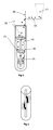
- FIG. 1 a represents the device of the invention in the case in which the annular zone 4 has dimensional variations linked to a change in the diameter of the external tube 6 .
- FIG. 1 b represents a slowing element in accordance with the invention in perspective.
- FIG. 1 c represents the device of the invention and the centring piece 12 viewed from above.
- FIG. 2 a represents the device of the invention in the case in which the annular zone 4 has dimensional variations and in which the internal tube 5 passed through its upper portion.
- FIG. 2 b represents a slowing element of the invention, viewed from above.
- FIG. 3 represents a variation of the device of the invention in which the slowing elements have a rigid peripheral structure, i.e. abutting the external tube 6 .
- FIG. 4 represents another variation of the device of the invention, in which the slowing elements are part-helical in shape.
- the present invention can be defined as a device for densely filling catalyst specially adapted to a steam reforming exchanger-reactor consisting of a plurality of bayonet tubes enclosed in a shell, each bayonet tube comprising an annular zone which is at least partially filled with catalyst.
- Said catalyst is constituted by solid particles occupying at least part of the annular space 4 included between an internal tube 5 and an external tube 6 , the assembly of these two tubes constituting the bayonet tube, the width of said annular space being in the range 30 mm to 80 mm, and its height being in the range 10 to 20 metres.
- the catalyst particles are generally in the form of cylinders with an approximate height of 10 mm to 20 mm and an approximate diameter of 5 mm to 20 mm.
- the device of the present invention consists of:
- a slowing element 7 has the general form of a ring with an internal diameter substantially equal to that of the internal tube 5 and with an external diameter substantially equal to that of the internal diameter of the external tube 6 .
- a slowing element 7 is defined by a rigid substantially horizontal annular structure which may either be central, i.e. surrounding the internal tube 5 , or peripheral, i.e. in contact with the internal wall of the external tube 6 .
- a plurality of flexible substantially radial rods is attached to this rigid annular structure so as to cover the whole section of the annular zone 4 .
- each slowing element 7 occupies the whole of the annular section 4 , the vertical distance separating two consecutive slowing elements being in the range 50 cm to 150 cm.
- each bayonet tube forms a continuous space and only in its upper portion does it have an obstacle constituted by the internal tube 5 passing through the external tube 6 .
- This obstacle poses a problem when deploying the device of the invention and may be overcome by opening the rigid circular structure, for example over a half-circumference, so as to be able to be engaged around the internal tube 5 , then closing said rigid structure using a clamping system 11 , the clamping system itself being provided with substantially radial flexible rods.
- the rigid structure of the slowing elements may be opened by being divided into two or 3 parts, then re-closed using any fixing means when the obstacle has been passed.
- ballast When a device is being put into position, a ballast may be added to the first slowing element to facilitate its deployment into the portion of the annular zone 4 with the smallest diameter.
- the first slowing element 7 is equipped with a weight which can overcome the friction of the flexible rods on the wall of the external tube 6 in the case of a rigid central structure, or internal tube, 5 , in the case of a rigid peripheral structure.
- the present invention also concerns a method for loading catalyst using the device described above, which method can be broken down into the following series of steps:
- the present invention can be defined as a device for the dense loading of catalyst into the annular space 4 of bayonet tubes, each bayonet tube having a height in the range 10 m to 20 m, a diameter of the external tube 6 in the range 250 mm to 150 mm, and an external diameter of the internal tube 5 in the range 10 to 40 mm.
- the annular space 4 containing the catalyst thus has a characteristic width of approximately 50 mm.
- the characteristic width of the annular space 4 can vary between 30 mm and 80 mm.
- the external tube 6 has a diameter which decreases from top to bottom in sections, which means that the characteristic width of the annular space 4 also reduces from top to bottom.
- the device of the invention is designed to adapt itself to these variations in characteristic width and retain its performance over the whole series of sections.
- an internal tube 5 which passes through the external tube 6 in the upper portion of the annular zone 4 to provide an outlet which is completely free of reaction effluents, has to be contended with.
- the slowing elements 7 can be used to get round this obstacle when positioning the device by having a rigid structure which can be opened up into several parts, generally two, then closed up again after passing round the obstacle using any fixing means known to the skilled person.
- the device of the present invention considerably reduces the risk of arching over since the solid particles will be slowed down by passing through the flexible rods of the slowing elements and will be deposited gradually over the surface of the bed.
- the fall height of the particles from the first slowing element (counted from bottom to top) to the surface of the catalytic bed which is being formed is at most 1 metre.
- loading is carried out tube by tube (or in groups of two or three tubes supplied in parallel), and so it has to be sufficiently rapid for industrial use, because a steam reforming reactor aimed at a production of approximately 100000 Nm 3 /h of H 2 generally includes 200 to 350 bayonet tubes.
- the filling device of the invention consists of:
- the annular space 4 which is thus defined may be a single space or be divided into several substantially identical sectors by means of a system termed a “centring piece” 12 .
- a sector is thus defined as a portion of the annular space which corresponds to a well-defined fraction of the annular section and extends over the entire height of said annular space.
- Each slowing element 7 is in the shape of a rigid circular ring abutting either the internal tube 5 or the external tube 6 , this ring being provided with a plurality of radial flexible rods which occupy the entire section of the annular zone 4 .
- the slowing elements 7 may be provided with rigid fins 9 disposed in a radial manner and extending over the whole width of the annular zone 4 , as can be seen in FIG. 1 b.
- the slowing elements 7 have a rigid structure in the form of helical sections, the flexible rods being attached in a radial manner right along the helical section.
- the helical shape of the rigid structure allows it to very easily get past the obstacle constituted by the crossover of the internal tube 5 in the upper portion of the annular zone 4 or the crossover of the centring piece 12 allowing correct positioning of the internal tube 5 .
- the first slowing element 7 is that which is always placed closest to the surface of the catalytic bed which is being formed.
- Loading tests were carried out with the device of the invention constituted by two slowing elements 7 disposed in an experimental 1 m high column constituted by an internal tube 5 with an external diameter of 42 mm and an external tube 6 with an internal diameter of 128.1 mm.
- the solid particles to be loaded were in the shape of small cylinders with a height of 1.5 cm and a diameter of 0.8 cm.
- a slowing element 7 has a rigid circular structure in the shape of a spiral with an internal diameter of 45 mm onto which a plurality of substantially radial flexible rods had been attached.
- the distance between the first slowing element 7 and the surface of the bed being formed was kept equal to 50 mm during loading.
- the device was continuously lifted at a speed of 0.3 metre/min.
- the ⁇ P was measured with a flow of air of 130 Nm 3 /h.
- the loading time was a maximum of 3.3 minutes /metre, which corresponded to a time of approximately 40 minutes for a 12 m tube (for a solid flow rate of approximately 320 kg/h).
- the loading density was 1009 kg/m 3 , reproducible across all of the loads.
Landscapes
- Chemical & Material Sciences (AREA)
- Organic Chemistry (AREA)
- Chemical Kinetics & Catalysis (AREA)
- Devices And Processes Conducted In The Presence Of Fluids And Solid Particles (AREA)
- Feeding, Discharge, Calcimining, Fusing, And Gas-Generation Devices (AREA)
- Hydrogen, Water And Hydrids (AREA)
- Catalysts (AREA)
Applications Claiming Priority (4)
| Application Number | Priority Date | Filing Date | Title |
|---|---|---|---|
| FR1202771A FR2996784B1 (fr) | 2012-10-17 | 2012-10-17 | Systeme de chargement dense du catalyseur dans des tubes a baionnette pour reacteur echangeur de vaporeformage faisant appel a des ralentisseurs souples et amovibles |
| FR1202771 | 2012-10-17 | ||
| FR12/02771 | 2012-10-17 | ||
| PCT/FR2013/052242 WO2014060670A1 (fr) | 2012-10-17 | 2013-09-24 | Systeme de chargement dense du catalyseur dans des tubes a baïonnette pour reacteur echangeur de vaporeformage |
Publications (2)
| Publication Number | Publication Date |
|---|---|
| US20150283529A1 US20150283529A1 (en) | 2015-10-08 |
| US9492802B2 true US9492802B2 (en) | 2016-11-15 |
Family
ID=47878101
Family Applications (1)
| Application Number | Title | Priority Date | Filing Date |
|---|---|---|---|
| US14/436,153 Expired - Fee Related US9492802B2 (en) | 2012-10-17 | 2013-09-24 | System for dense loading of catalyst into bayonet tubes for a steam reforming exchanger-reactor using flexible and removable slowing elements |
Country Status (8)
| Country | Link |
|---|---|
| US (1) | US9492802B2 (fr) |
| EP (1) | EP2908933B1 (fr) |
| JP (1) | JP6248115B2 (fr) |
| CN (1) | CN104736233B (fr) |
| CA (1) | CA2884948A1 (fr) |
| FR (1) | FR2996784B1 (fr) |
| RU (1) | RU2630107C2 (fr) |
| WO (1) | WO2014060670A1 (fr) |
Families Citing this family (4)
| Publication number | Priority date | Publication date | Assignee | Title |
|---|---|---|---|---|
| JP6993664B2 (ja) * | 2017-04-20 | 2022-01-13 | 国立研究開発法人日本原子力研究開発機構 | 触媒充填方法 |
| CN108745211B (zh) * | 2018-08-08 | 2023-09-01 | 德艾柯工程技术(上海)有限公司 | 一种板式反应器催化剂装填装置 |
| US11253830B2 (en) * | 2019-02-08 | 2022-02-22 | Air Liquide Large Industries U.S. Lp | Apparatus for installing a thermocouple inside a reactor tube filled with catalyst |
| EP3950114B1 (fr) * | 2019-03-29 | 2023-06-07 | Mitsubishi Chemical Corporation | Procédé de chargement de substance granulée |
Citations (12)
| Publication number | Priority date | Publication date | Assignee | Title |
|---|---|---|---|---|
| US5247970A (en) * | 1991-12-20 | 1993-09-28 | Norsk Hydro A.S. | Method for filling particulate material into tubes |
| FR2789050A1 (fr) | 1999-01-28 | 2000-08-04 | Total Raffinage Distribution | Procede et dispositif pour faciliter le remplissage de tubes verticaux a l'aide d'un materiau particulaire |
| US6467513B1 (en) * | 1998-12-25 | 2002-10-22 | Toyo Engineering Corporation | Method for packing catalyst and device therefor |
| US20060213575A1 (en) * | 2005-03-25 | 2006-09-28 | Mcnaughton Michael D | Filling tubes with catalyst and/or other particulate |
| EP1749568A1 (fr) | 2005-07-28 | 2007-02-07 | Aldo Cota | Dispositif pour le chargement de matériaux en grain dans des tubes |
| WO2007039764A1 (fr) | 2005-10-04 | 2007-04-12 | Johnson Matthey Plc | Procédé de chargement de catalyseur |
| US20080298932A1 (en) | 2007-06-01 | 2008-12-04 | Paul Fry | Catalyst Loading System |
| US20090257849A1 (en) | 2008-04-15 | 2009-10-15 | Petroleo Brasileiro S.A. - Petrobras | Apparatus and method for loading particulate material into vertical tubes |
| US20100175775A1 (en) * | 2007-08-13 | 2010-07-15 | Unidense Technology Gmbh | Catalyst loading system |
| WO2011012875A1 (fr) | 2009-07-28 | 2011-02-03 | Johnson Matthey Plc | Procédé et appareil dinstallation de dispositif de surveillance |
| FR2950822A1 (fr) | 2009-10-01 | 2011-04-08 | Inst Francais Du Petrole | Dispositif de chargement de particules de catalyseur dans des tubes presentant une zone annulaire |
| US20110250102A1 (en) * | 2010-03-29 | 2011-10-13 | Toyo Engineering Corporation | Reactor |
Family Cites Families (2)
| Publication number | Priority date | Publication date | Assignee | Title |
|---|---|---|---|---|
| JPS60112338U (ja) * | 1983-12-28 | 1985-07-30 | 三井東圧化学株式会社 | 触媒充填機 |
| JP2005211808A (ja) * | 2004-01-30 | 2005-08-11 | Mitsubishi Heavy Ind Ltd | ジメチルエーテル改質触媒 |
-
2012
- 2012-10-17 FR FR1202771A patent/FR2996784B1/fr not_active Expired - Fee Related
-
2013
- 2013-09-24 CA CA2884948A patent/CA2884948A1/fr not_active Abandoned
- 2013-09-24 JP JP2015537323A patent/JP6248115B2/ja not_active Expired - Fee Related
- 2013-09-24 US US14/436,153 patent/US9492802B2/en not_active Expired - Fee Related
- 2013-09-24 WO PCT/FR2013/052242 patent/WO2014060670A1/fr active Application Filing
- 2013-09-24 RU RU2015118355A patent/RU2630107C2/ru not_active IP Right Cessation
- 2013-09-24 CN CN201380054518.7A patent/CN104736233B/zh not_active Expired - Fee Related
- 2013-09-24 EP EP13782755.6A patent/EP2908933B1/fr not_active Not-in-force
Patent Citations (19)
| Publication number | Priority date | Publication date | Assignee | Title |
|---|---|---|---|---|
| US5247970A (en) * | 1991-12-20 | 1993-09-28 | Norsk Hydro A.S. | Method for filling particulate material into tubes |
| US6467513B1 (en) * | 1998-12-25 | 2002-10-22 | Toyo Engineering Corporation | Method for packing catalyst and device therefor |
| FR2789050A1 (fr) | 1999-01-28 | 2000-08-04 | Total Raffinage Distribution | Procede et dispositif pour faciliter le remplissage de tubes verticaux a l'aide d'un materiau particulaire |
| US20060213575A1 (en) * | 2005-03-25 | 2006-09-28 | Mcnaughton Michael D | Filling tubes with catalyst and/or other particulate |
| EP1749568A1 (fr) | 2005-07-28 | 2007-02-07 | Aldo Cota | Dispositif pour le chargement de matériaux en grain dans des tubes |
| US20090090429A1 (en) | 2005-10-04 | 2009-04-09 | Johnson Matthey Plc | Catalyst loading apparatus |
| WO2007039764A1 (fr) | 2005-10-04 | 2007-04-12 | Johnson Matthey Plc | Procédé de chargement de catalyseur |
| US20110150624A1 (en) | 2007-06-01 | 2011-06-23 | Paul Fry | Catalyst Loading System |
| WO2008151139A1 (fr) | 2007-06-01 | 2008-12-11 | Catalyst Services, Inc. | Système de chargement de catalyseur |
| US20080298932A1 (en) | 2007-06-01 | 2008-12-04 | Paul Fry | Catalyst Loading System |
| US8025472B2 (en) | 2007-06-01 | 2011-09-27 | Catalyst Services, Inc. | Catalyst loading system |
| US20100175775A1 (en) * | 2007-08-13 | 2010-07-15 | Unidense Technology Gmbh | Catalyst loading system |
| US20090257849A1 (en) | 2008-04-15 | 2009-10-15 | Petroleo Brasileiro S.A. - Petrobras | Apparatus and method for loading particulate material into vertical tubes |
| WO2011012875A1 (fr) | 2009-07-28 | 2011-02-03 | Johnson Matthey Plc | Procédé et appareil dinstallation de dispositif de surveillance |
| US20120125479A1 (en) * | 2009-07-28 | 2012-05-24 | Johnson Matthey Plc | Monitoring device installation method and apparatus |
| US20110083769A1 (en) | 2009-10-01 | 2011-04-14 | IFP Energies Nouvelles | Device for loading particles of catatlyst into tubes having an annular zone |
| FR2950822A1 (fr) | 2009-10-01 | 2011-04-08 | Inst Francais Du Petrole | Dispositif de chargement de particules de catalyseur dans des tubes presentant une zone annulaire |
| US8578978B2 (en) | 2009-10-01 | 2013-11-12 | IFP Energies Nouvelles | Device for loading particles of catalyst into tubes having an annular zone |
| US20110250102A1 (en) * | 2010-03-29 | 2011-10-13 | Toyo Engineering Corporation | Reactor |
Non-Patent Citations (3)
| Title |
|---|
| English Translation Abstract of EP 1749568 Al published Feb. 7, 2007. |
| English Translation Abstract of FR 2789050 Al published Aug. 4, 2000. |
| International Search Report dated Jan. 20, 2014 issued in corresponding PCT/FR2013/052242 application (pp. 1-3). |
Also Published As
| Publication number | Publication date |
|---|---|
| CN104736233B (zh) | 2017-08-08 |
| RU2015118355A (ru) | 2016-12-10 |
| FR2996784B1 (fr) | 2015-10-16 |
| JP2016500636A (ja) | 2016-01-14 |
| FR2996784A1 (fr) | 2014-04-18 |
| EP2908933A1 (fr) | 2015-08-26 |
| WO2014060670A1 (fr) | 2014-04-24 |
| JP6248115B2 (ja) | 2017-12-13 |
| EP2908933B1 (fr) | 2018-03-07 |
| CA2884948A1 (fr) | 2014-04-24 |
| RU2630107C2 (ru) | 2017-09-05 |
| CN104736233A (zh) | 2015-06-24 |
| US20150283529A1 (en) | 2015-10-08 |
Similar Documents
| Publication | Publication Date | Title |
|---|---|---|
| US9486764B2 (en) | System for dense loading of catalyst into bayonet tubes for a steam reforming exchanger-reactor using removable helical elements | |
| US9492802B2 (en) | System for dense loading of catalyst into bayonet tubes for a steam reforming exchanger-reactor using flexible and removable slowing elements | |
| US9623391B2 (en) | Monitoring device installation method and apparatus | |
| US9486766B2 (en) | Pneumatic system for densely loading catalyst into bayonet tubes for a steam reforming reactor-exchanger with a detachable feed tube for gas | |
| US9452400B2 (en) | System for dense loading of catalyst into bayonet tubes for a steam reforming exchanger-reactor using removable deflectors | |
| JP2011072992A (ja) | 触媒粒子を差込管の環状帯域へ充填する装置および方法 | |
| US20090090429A1 (en) | Catalyst loading apparatus | |
| US9452399B2 (en) | Pneumatic system for dense loading of catalyst into bayonet tubes for a steam reforming exchanger-reactor using an auxiliary tube for introducing solid particles | |
| US7067107B2 (en) | Furnace and steam reforming process |
Legal Events
| Date | Code | Title | Description |
|---|---|---|---|
| AS | Assignment |
Owner name: IFP ENERGIES NOUVELLES, FRANCE Free format text: ASSIGNMENT OF ASSIGNORS INTEREST;ASSIGNORS:SANZ, ELENA;BEAUMONT, ROBERT;SVEZIA, DANIEL;AND OTHERS;SIGNING DATES FROM 20150429 TO 20150505;REEL/FRAME:035773/0198 |
|
| STCF | Information on status: patent grant |
Free format text: PATENTED CASE |
|
| FEPP | Fee payment procedure |
Free format text: MAINTENANCE FEE REMINDER MAILED (ORIGINAL EVENT CODE: REM.); ENTITY STATUS OF PATENT OWNER: LARGE ENTITY |
|
| LAPS | Lapse for failure to pay maintenance fees |
Free format text: PATENT EXPIRED FOR FAILURE TO PAY MAINTENANCE FEES (ORIGINAL EVENT CODE: EXP.); ENTITY STATUS OF PATENT OWNER: LARGE ENTITY |
|
| STCH | Information on status: patent discontinuation |
Free format text: PATENT EXPIRED DUE TO NONPAYMENT OF MAINTENANCE FEES UNDER 37 CFR 1.362 |
|
| FP | Expired due to failure to pay maintenance fee |
Effective date: 20201115 |