US9490602B2 - Laser system able to estimate hermetic seal of laser gas container - Google Patents
Laser system able to estimate hermetic seal of laser gas container Download PDFInfo
- Publication number
- US9490602B2 US9490602B2 US14/196,608 US201414196608A US9490602B2 US 9490602 B2 US9490602 B2 US 9490602B2 US 201414196608 A US201414196608 A US 201414196608A US 9490602 B2 US9490602 B2 US 9490602B2
- Authority
- US
- United States
- Prior art keywords
- laser
- gas pressure
- oscillator
- gas
- initial operation
- Prior art date
- Legal status (The legal status is an assumption and is not a legal conclusion. Google has not performed a legal analysis and makes no representation as to the accuracy of the status listed.)
- Expired - Fee Related, expires
Links
- 238000001514 detection method Methods 0.000 claims abstract description 19
- 230000005855 radiation Effects 0.000 claims abstract description 9
- 230000010355 oscillation Effects 0.000 claims description 119
- 230000005284 excitation Effects 0.000 claims description 2
- 239000007789 gas Substances 0.000 description 245
- 238000012360 testing method Methods 0.000 description 79
- 238000012545 processing Methods 0.000 description 71
- 238000012986 modification Methods 0.000 description 15
- 230000004048 modification Effects 0.000 description 15
- 238000002474 experimental method Methods 0.000 description 7
- 230000002159 abnormal effect Effects 0.000 description 5
- 238000010586 diagram Methods 0.000 description 4
- 230000000694 effects Effects 0.000 description 4
- 239000012535 impurity Substances 0.000 description 4
- 238000011144 upstream manufacturing Methods 0.000 description 3
- XKRFYHLGVUSROY-UHFFFAOYSA-N Argon Chemical compound [Ar] XKRFYHLGVUSROY-UHFFFAOYSA-N 0.000 description 2
- CURLTUGMZLYLDI-UHFFFAOYSA-N Carbon dioxide Chemical compound O=C=O CURLTUGMZLYLDI-UHFFFAOYSA-N 0.000 description 2
- 238000000034 method Methods 0.000 description 2
- 239000003507 refrigerant Substances 0.000 description 2
- IJGRMHOSHXDMSA-UHFFFAOYSA-N Atomic nitrogen Chemical compound N#N IJGRMHOSHXDMSA-UHFFFAOYSA-N 0.000 description 1
- 229910052786 argon Inorganic materials 0.000 description 1
- 229910002092 carbon dioxide Inorganic materials 0.000 description 1
- 239000001569 carbon dioxide Substances 0.000 description 1
- 230000015556 catabolic process Effects 0.000 description 1
- 238000011109 contamination Methods 0.000 description 1
- 239000000498 cooling water Substances 0.000 description 1
- 238000012937 correction Methods 0.000 description 1
- 230000003247 decreasing effect Effects 0.000 description 1
- 238000006731 degradation reaction Methods 0.000 description 1
- 229910001873 dinitrogen Inorganic materials 0.000 description 1
- 239000003814 drug Substances 0.000 description 1
- 238000012423 maintenance Methods 0.000 description 1
- 238000005259 measurement Methods 0.000 description 1
- 230000002093 peripheral effect Effects 0.000 description 1
Images


Classifications
-
- H—ELECTRICITY
- H01—ELECTRIC ELEMENTS
- H01S—DEVICES USING THE PROCESS OF LIGHT AMPLIFICATION BY STIMULATED EMISSION OF RADIATION [LASER] TO AMPLIFY OR GENERATE LIGHT; DEVICES USING STIMULATED EMISSION OF ELECTROMAGNETIC RADIATION IN WAVE RANGES OTHER THAN OPTICAL
- H01S3/00—Lasers, i.e. devices using stimulated emission of electromagnetic radiation in the infrared, visible or ultraviolet wave range
- H01S3/0014—Monitoring arrangements not otherwise provided for
-
- H—ELECTRICITY
- H01—ELECTRIC ELEMENTS
- H01S—DEVICES USING THE PROCESS OF LIGHT AMPLIFICATION BY STIMULATED EMISSION OF RADIATION [LASER] TO AMPLIFY OR GENERATE LIGHT; DEVICES USING STIMULATED EMISSION OF ELECTROMAGNETIC RADIATION IN WAVE RANGES OTHER THAN OPTICAL
- H01S3/00—Lasers, i.e. devices using stimulated emission of electromagnetic radiation in the infrared, visible or ultraviolet wave range
- H01S3/02—Constructional details
- H01S3/03—Constructional details of gas laser discharge tubes
- H01S3/036—Means for obtaining or maintaining the desired gas pressure within the tube, e.g. by gettering, replenishing; Means for circulating the gas, e.g. for equalising the pressure within the tube
Definitions
- the present invention relates to a laser system which can estimate the hermetic seal of a laser gas container in which a laser gas is sealed.
- a laser system which measures the pressure before turning off the power of the laser system, stores it in the memory, and compares this stored gas pressure with gas pressure which is measured when the power of the laser system is turned on so as to detect gas leakage of the laser gas container.
- the system which is described in Japanese Utility Model Registration No. 2561510Y JP2561510Y also measures the gas temperature when measuring the gas pressure, converts the measured gas pressure to a pressure at a reference temperature, and uses the converted value to detect gas leakage.
- JP2561510Y does not detect gas leakage in a state where gas leakage easily occurs. It is hard for it to detect gas leakage easily and accurately.
- the laser system includes a laser gas container forming a gas channel in which laser gas circulates, a laser oscillator oscillating laser light by using laser gas flowing through the gas channel as an excitation medium, a gas pressure detector detecting a laser gas pressure in the laser gas container, a pressure adjusting part adjusting the laser gas pressure in the laser gas container based on a value detected by the gas pressure detector, a pressure control unit controlling the pressure adjusting part so that before startup of the laser oscillator, the laser gas pressure in the laser gas container becomes a first gas pressure lower than atmospheric pressure and so that at a preparatory stage after startup of the laser oscillator and before laser light is radiated to an outside, the laser gas pressure in the laser gas container becomes a second gas pressure capable of oscillating laser light, a laser control unit controlling the laser oscillator so that the laser oscillator executes an initial operation in which the laser oscillator outputs laser light in accordance with a predetermined oscillation condition at the preparatory stage, a laser detector
- FIG. 1 is a view which schematically shows the configuration of a laser system according to a first embodiment of the present invention
- FIG. 2 is a block diagram which shows part of a control configuration of a laser system according to a first embodiment of the present invention
- FIG. 3 is a flowchart which shows one example of oscillator shutdown processing executed by a control unit of FIG. 2 ,
- FIG. 4 is a flowchart which shows one example of oscillator startup processing executed by a control unit of FIG. 2 ,
- FIG. 5 is a flow chart which shows a modification of FIG. 4 .
- FIG. 6 is a flowchart which shows one example of oscillator startup processing which is executed by a control unit of a laser system according to a second embodiment of the present invention
- FIG. 7 is a flow chart which shows a modification of FIG. 6 .
- FIG. 8 is a flowchart which shows one example of oscillator startup processing which is executed by a control unit of a laser system according to a third embodiment of the present invention
- FIG. 9 is a flow chart which shows a modification of FIG. 8 .
- FIG. 10 is a flow chart which shows a modification of FIG. 9 .
- FIG. 11 is a flow chart which shows a modification of FIG. 10 .
- FIG. 12 is a flowchart which shows one example of oscillator powerup processing which is executed by a control unit of a laser system according to a fourth embodiment of the present invention
- FIG. 13 is a flowchart which shows one example of oscillator startup processing which is executed by a control unit of a laser system according to a fourth embodiment of the present invention
- FIG. 14 is a flow chart which shows a modification of FIG. 13 .
- FIG. 15 is a flow chart which shows another modification of FIG. 13 .
- FIG. 16 is a block diagram which shows the control configuration of a laser system which corresponds to the processing of FIG. 15 .
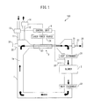
- FIG. 1 is a view which schematically shows a laser system 100 according to the first embodiment of the present invention.
- This laser system 100 is provided with a laser gas container 1 which forms a gas channel 1 a through which laser gas circulates, a laser oscillator 2 and blower 3 which are arranged on the gas channel 1 a , and a control unit 5 which controls the laser oscillator 2 and blower 3 .
- the laser system 100 according to the present embodiment can be used in a broad range of fields such as processing, medicine, and measurement.
- the laser gas container 1 is a hermetically sealed vacuum container. Inside the laser gas container 1 , a predetermined laser gas is sealed in a state cut off from the air.
- media gas for laser oscillation use which includes carbon dioxide gas, nitrogen gas, argon gas, or another laser media is used.
- the laser oscillator 2 has an output mirror 21 , rear mirror 22 , and discharge tube 23 which is arranged between the output mirror 21 and the rear mirror 22 .
- the discharge tube 23 communicates with the gas channel 1 a .
- the discharge tube 23 is supplied with power from the laser power source 24 .
- the laser gas is excited while passing through the discharge tube 23 and becomes a laser active state.
- the light generated by the discharge tube 23 is amplified between the output mirror 21 and rear mirror 22 to oscillate whereby laser light is generated.
- the output mirror 21 is a partial transparent mirror. Laser light which passes through the output mirror 21 becomes output laser light 27 , and then is output to the outside. This laser light 27 passes through an openable and closable shutter 25 and is radiated toward an object. At the side of the rear mirror 22 , a laser detector 26 which detects the output of the laser light 27 which passes through the rear mirror 22 is provided.
- the laser detector 26 can be configured by photodiode, thermopile, etc.
- the blower 3 is comprised of a fan or blower which is driven by an electric motor.
- the blower 3 is supplied with power through a not shown blower inverter. Due to this power, the blower 3 operates and makes the laser gas circulate along the gas channel 1 a .
- a first heat exchanger 31 and a second heat exchanger 32 are arranged.
- a predetermined refrigerant for example cooling water
- the laser gas is cooled by heat exchange with this refrigerant while passing through the heat exchangers 31 and 32 and thereby held at a predetermined temperature.
- a feed device 13 is provided at the gas feed channel 11 .
- laser gas is supplied from a high pressure tank (not shown) in which the laser gas is stored to the inside of the gas channel 1 a .
- an exhaust device 14 is provided at the gas exhaust channel 12 . Laser gas is exhausted through the exhaust device 14 from the gas channel 1 a .
- the feed device 13 and exhaust device 14 are configured including shutoff valves.
- laser gas is continuously fed through the gas feed channel 11 and gas exhaust channel 12 to the gas channel 1 a whereby fine amounts of the laser gas in the laser gas container 1 are replaced.
- a gas pressure detector 33 is provided at the downstream side of the first heat exchanger 31 and the upstream side of the blower 30 . The gas pressure inside the laser gas container 1 is detected by the gas pressure detector 33 .
- the laser gas container 1 is sealed.
- degradation of the O-rings or other seal members or looseness of the joints, etc. lead to leakage of laser gas from the laser gas container 1 or entry of air into the laser gas container 1 , and thus the quality of the laser gas may be deteriorated.
- the control unit 5 executes the following processing to estimate the extent of the hermetic seal.
- the time of startup of the laser oscillator 2 corresponds to the period from the start of startup of the laser oscillator 2 to the completion of startup, that is, the preparatory stage from when the power of the laser oscillator 2 is turned on to when radiating the laser is commanded.
- the shutter 25 is closed and the laser is not radiated to the outside.
- FIG. 2 is a block diagram which shows part of the control configuration of the laser system 100 according to the first embodiment of the present invention.
- the control unit 5 is comprised of a processing system which has an CPU, ROM, RAM, and other peripheral circuits, etc.
- the control unit 5 has a pressure control unit 51 which controls the pressure inside of the laser gas container 1 and a power control unit (laser control unit 52 ) which controls the power which is supplied from the laser power source 24 to the laser oscillator 2 .
- the control unit 5 executes processing to shut down the laser oscillator 2 (oscillator shutdown processing) and processing to start up the laser oscillator 2 (oscillator startup processing).
- the control unit 5 receives as input signals from the laser detector 26 , gas pressure detector 33 , and input part 4 through which the user inputs various commands.
- the control unit 5 outputs control signals to the laser power source 24 , blower 3 (blower inverter), feed device 13 , exhaust device 14 , shutter 25 , and display unit 6 and controls their operations.
- FIG. 3 is a flowchart which shows an example of the oscillator shutdown processing.
- the processing which is shown in this flowchart is, for example, started when shutdown of the laser oscillator 2 is instructed through the input part 4 .
- the power of the laser oscillator 2 (laser power source 24 ) is turned off.
- the rotation of the blower 3 is stopped. Due to this, circulation of the laser gas in the laser gas container 1 is stopped.
- the gas pressure inside of the laser gas container 1 is adjusted so that the gas pressure which is detected by the gas pressure detector 33 becomes a predetermined gas pressure G 0 (target gas pressure) which is lower than the atmospheric pressure around the laser system 100 .
- This adjustment is performed by controlling the feed device 13 and exhaust device 14 to feed and exhaust laser gas to and from the laser gas container.
- the shutoff valve of the feed device 13 , the shutoff valve of the exhaust device 14 , and all other valves which are connected to the gas laser container 1 are closed. Due to this, the laser gas container 1 is rendered a hermetically sealed state. With the above, the oscillator shutdown processing is ended.
- the target gas pressure G 0 of step S 3 may be set to this gas pressure Ga. Due to this, by just closing the shutoff valves of the feed device 13 and exhaust device 14 and cutting off the flow of laser gas (step S 4 ), the gas pressure can be adjusted to the target gas pressure G 0 .
- the target gas pressure G 0 need only be lower than atmospheric pressure.
- the target gas pressure G 0 can also be set to a value which is higher than the gas pressure Gas during laser oscillation. In this case, it is sufficient to fill laser gas inside the laser gas container 1 to adjust it to the target gas pressure G 0 .
- the gas pressure Ga during laser oscillation is higher than atmospheric pressure, it is possible to exhaust laser gas from inside the laser gas container 1 to adjust the gas pressure P to the target gas pressure G 0 . It is also possible to adjust the gas pressure at step S 3 after stopping the blower 3 , then waiting until the gas pressure stabilizes.
- the laser gas container 1 After the oscillator shutdown processing, the laser gas container 1 is held in a hermetically sealed state and laser gas is not fed or exhausted inside the laser gas container 1 . Therefore, compared with feeding and exhausting laser gas as required, it is possible to suppress the amount of consumption of laser gas.
- the laser gas container 1 is left uncontrolled in the hermetically sealed state.
- the gas pressure in the hermetically sealed state is made lower than atmospheric pressure, so when there is a problem in the seal of the laser gas container 1 , air enters the laser gas container 1 . Due to this, the quality of the laser gas deteriorates and the laser output falls.
- the extent of the hermetic seal of the laser gas container 1 is estimated in accordance with the magnitude of the laser output. The lower the target gas pressure G 0 is made compared with atmospheric pressure, the more easy it is for air to enter the laser gas container 1 and the more easy it is to estimate the hermetic seal.
- FIG. 4 is a flowchart which shows an example of oscillator startup processing. For example, if a command is given through the input part 4 to turn on the power of the laser oscillator 2 (laser power source 24 ), the laser power source 24 turns on, startup of the laser oscillator 2 becomes possible, and the routine of FIG. 4 is started.
- a control signal is output to the blower 3 and the blower 3 is started up. Due to this, the laser gas circulates through the inside of the laser gas container 1 .
- the gas pressure which is detected by the gas pressure detector 33 is made to become a predetermined gas pressure G 1 by adjusting the gas pressure inside of the laser gas container 1 . This adjustment is performed by controlling the feed device 13 and exhaust device 14 to supply and discharge laser gas to and from the laser gas container 1 .
- the gas pressure G 1 is the optimum gas pressure for laser oscillation (gas pressure when radiating laser) and, for example, is higher than the target gas pressure G 0 .
- a control signal is output to the laser power source 24 and laser light is output from the laser oscillator 2 in accordance with a predetermined oscillation condition. That is, in an initial operation of the laser oscillator 2 , the laser oscillation is performed on a test basis (laser oscillation test run). For example, a laser oscillation test run by the laser output command P 1 (W) and the duty command D 1 (%) as pulse commands is performed for exactly T 1 seconds. At this time, the output of the laser light which is generated by the laser oscillation test run is detected by the laser detector 26 .
- a representative value Pa 1 of the laser output detected by the laser detector 26 is stored in the memory. For example, the average value of the laser outputs which are detected during a predetermined time T 1 or the value of the laser output which is detected at the end (after T 1 seconds) is stored as the representative value Pa 1 .
- this laser output value Pa 1 (hereinafter, sometimes called “laser output Pa 1 ”) is used as the basis to estimate the extent of hermetic seal of the laser gas container 1 .
- the estimated leak rate L 1 unit: Pa/hour
- the state of a large estimated leak rate L 1 is the state where air enters the laser gas container 1 and the quality of the laser gas deteriorates. If the estimated leak rate L 1 becomes larger, the ratio of impurities in the laser gas increases and the laser output value Pa 1 becomes smaller.
- the relationship between the laser output value Pa 1 and the estimated leak rate L 1 that is, the relationship of the estimated leak rate L 1 decreasing along with the increase of the laser output value Pa 1 , is determined in advance by experiments, etc. and stored in the memory.
- this relationship is used to determine the estimated leak rate L 1 . Due to this, it is possible to estimate the extent of hermetic seal of the laser gas container 1 .
- a control signal is output to the display unit 6 , and the estimated leak rate L 1 corresponding to the laser output value Pa 1 is displayed. Due to this, the user can easily obtain a grasp of the extent of hermetic seal of the laser gas container 1 .
- the oscillator startup processing is ended.
- the startup of the laser oscillator 2 completes and is rendered a state able to receive a laser radiation command. In this state, when the laser radiation is commanded through the input part 4 , the shutter 25 is opened and laser light is radiated.
- the gas pressure inside of the laser gas container 1 is adjusted to the target gas pressure G 0 which is larger than atmospheric pressure (step S 3 ).
- the gas pressure inside the laser gas container 1 is adjusted to the gas pressure G 1 suitable for radiating the laser (step S 12 ).
- the laser oscillator 2 is made to oscillate laser light on a test basis under the predetermined oscillation condition (step S 13 ), the estimated leak rate L 1 is determined from the laser output value Pa 1 which is obtained by the laser oscillation test run (step S 15 ), and the rate is displayed on the display unit 6 (step S 16 ).
- FIG. 5 is a flow chart which shows a modification of FIG. 4 .
- the same portions as shown in FIG. 4 are assigned the same reference notations.
- the laser output Pa 1 after the laser oscillation test run is stored in a memory, then the routine proceeds to step S 17 .
- the reference value Pt 1 is the threshold value for judging the quality of the hermetic seal and is set to a value which becomes a reference for whether replacement of a seal member or other maintenance is required.
- step S 17 If the positive decision is made at step S 17 , the routine proceeds to step S 18 , while if the negative decision is made, the routine bypasses step S 18 and ends the processing.
- step S 18 it outputs a control signal to the display unit 6 and displays a warning to indicate the effect that the hermetic seal is poor. Due to this, the user can judge the quality of the hermetic seal of the laser gas container 1 . In the example of FIG. 5 , a warning is displayed only when the hermetic seal is poor, that is, when there is an effect on the laser output which might become a problem, so it is possible to easily judge the quality of the hermetic seal.
- the second embodiment differs from the first embodiment in the oscillator startup processing in the control unit 5 .
- oscillator shutdown processing similar to the first embodiment is performed.
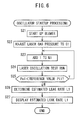
- FIG. 6 is a flowchart which shows an example of the oscillator startup processing which is executed by the control unit 5 of the second embodiment.
- the processing of step S 21 and step S 22 is the same as the processing of step S 11 and step S 12 of FIG. 4 . That is, at step S 21 , the blower 3 is started up, while at step S 22 , the laser gas pressure is adjusted to the optimal gas pressure G 1 for laser oscillation.
- the number N 1 of times of execution of the laser oscillation test run is incremented by exactly “1” and stored in the memory. N 1 is set to 0 in the initial state.
- a predetermined laser oscillation test run (laser output command P 1 and duty command D 1 as pulse commands) is executed for exactly a predetermined time T 1 .
- step S 25 it is judged if the laser output Pa 1 is smaller than the predetermined reference value Pt 1 .
- the reference value Pt 1 is, for example, set to the equivalent of the laser output when the laser is radiated in the normal state where the laser gas is not contaminated by impurities. If the positive decision is made at step S 25 , the routine returns to step S 23 . Due to this, the laser oscillation test run is repeated until the laser output Pa 1 reaches the reference value Pt 2 , and the number of times the laser oscillation test run is executed is counted. If the laser gas contains impurities, the initial laser output Pa 1 is small. However, the laser output Pa 1 rises each time repeating the laser oscillation test run. If the laser output Pa 1 reaches the reference value Pt 1 , the negative decision is made at step S 25 and the routine proceeds to step S 26 .
- the number N 1 of times of execution of the laser oscillation test run is used to estimate the extent of hermetic seal of the laser gas container 1 .
- the estimated leak rate L 1 there is a predetermined correlative relationship that the larger the number N 1 of times of execution, the larger the estimated leak rate L 1 . This relationship is determined in advance by experiments, etc. and stored in the memory.
- the estimated leak rate L 1 corresponding to the number N 1 of times of execution is determined from this relationship.
- step S 27 in the same way as step S 16 of FIG. 4 , the estimated leak rate L 1 is displayed on the display unit 6 and the oscillator startup processing is ended.
- the oscillator shutdown processing is used to adjust the gas pressure inside of the laser gas container 1 to a gas pressure G 0 lower than atmospheric pressure, then the oscillator startup processing is used to repeat the laser oscillation test run until the laser output Pa 1 reaches the reference value Pt 1 (step S 23 to step S 25 ) and the estimated leak rate L 1 is determined from the number N 1 of times of execution of the laser oscillation test run (step S 26 ).
- the user can easily and accurately obtain a grasp of the extent of the hermetic seal of the laser gas container 1 and the rise in price of the laser system 100 can be kept down. Further, when the oscillator startup processing is completed, the laser output Pa 1 becomes the reference value Pt 1 or more, so the laser output is stable and good laser light can be emitted immediately when the laser radiation is commanded. Instead of displaying the estimated leak rate L 1 , in the same way as FIG. 5 , it is also possible to judge the quality of the hermetic seal of the laser gas container 1 .
- step S 26 and step S 27 it is judged if the number N 1 of times of execution of the laser oscillation test run is the predetermined number Nt of times used as the reference for judgment of quality or more. If N 1 is equal to or more than Nt, a warning may be displayed.
- FIG. 7 is a flow chart which shows a modification of FIG. 6 .
- the laser output Pa 1 at the time of end of the laser oscillation test run at the previous oscillator startup processing is used to set the reference value Pt (reference value Pt 1 of FIG. 6 ). That is, at step S 29 , the laser output Pa 1 when the laser oscillation test run is repeated and the laser output reaches the reference value Pt 1 is stored in the memory as the laser output Pp at the time of the previous oscillation startup processing.
- this laser output Pp is used to set the reference value Pt 1 at the time of the current oscillation startup processing. For example, Pp multiplied with a predetermined coefficient (for example 0.9) is set as the reference value Pt 1 .
- the relative magnitude of the reference value Pt 1 and the laser output Pa 1 is judged.
- the actual laser output Pa 1 (Pp) obtained by the laser oscillation test run is used to set the reference value Pt 1 of the laser oscillation test run in the next oscillator startup processing, so even if there is variation in the characteristics for each laser system 100 , it is possible to raise the laser output precisely to the desired laser output suited for radiating the laser.
- the third embodiment differs from the second embodiment in the oscillator startup processing in the control unit 5 .
- oscillator shutdown processing similar to the first embodiment is executed.
- the laser oscillation test run is repeated until the laser output reaches the reference value Pt 1 .
- a plurality of oscillation conditions first oscillation condition and second oscillation condition are set and the laser oscillation test run is repeat under the respective oscillation conditions.
- laser oscillation test run 1 a laser oscillation test run which corresponds to the first oscillation condition
- laser oscillation test run 2 a laser oscillation test run which corresponds to the second oscillation condition
- FIG. 8 is a flowchart which shows one example of the oscillator startup processing executed at the control unit 5 of the third embodiment.
- the same processing as step S 21 to step S 24 of FIG. 6 is executed. That is, as the first initial operation, the laser oscillation test run 1 is repeated in accordance with the first oscillation condition until the laser output Pa 1 reaches the reference value Pt 1 (first reference value).
- the laser oscillation is performed for exactly the predetermined time T 1 (first predetermined time) in accordance with the laser output command P 1 (first laser output command) and the duty command D 1 (first duty command) as pulse commands.
- step S 36 a laser oscillation test run 2 is executed in accordance with the second oscillation condition until the laser output (below, this expressed by Pa 2 to differentiate it from the laser output Pa 1 of the first initial operation) reaches the second reference value Pt 2 .
- the number N 2 of times of execution of the laser oscillation test run 2 is incremented by exactly “1”. N 2 is set to “0” in the initial state.
- the laser oscillation test run 2 is executed in accordance with predetermined second oscillation condition. That is, the laser oscillation is performed for exactly the predetermined time T 2 (second predetermined time) in accordance with the laser output command P 2 (second laser output command) and the duty command D 2 (second duty command) as pulse commands.
- the second laser output command P 2 is set to a value larger than the first laser output command P 1 . Due to this, in the laser oscillation test run 2 , laser oscillation of a higher output than the laser oscillation test run 1 becomes possible.
- the second duty command D 2 and the second predetermined time t 2 are, for example, the same values as the first duty command D 1 and first predetermined time T 1 .
- the second reference value Pt 2 is set to a value which is larger than the first reference value Pt 1 .
- step S 38 If the positive decision is made at step S 38 , the routine returns to step S 36 where the number N 2 of times of execution of the laser oscillation test run 2 is incremented by “1”. When the laser output Pa 2 reaches the reference value Pt 2 , the routine proceeds to step S 39 .
- the number N 1 of times of execution of the laser oscillation test run 1 and the number N 2 of times of execution of the laser oscillation test run 2 are used as the basis to determine the estimated leak rate L 2 .
- the relationship between the total number of times of execution combining N 1 and N 2 and the estimated leak rate L 1 specifically, the relationship where the greater the total number of times of execution, the larger estimated leak rate L 1 , is determined in advance by experiments, etc. and stored in the memory. This relationship is used to determine the estimated leak rate L 1 corresponding to the numbers N 1 and N 2 of times of execution.
- step S 40 the estimated leak rate L 1 is displayed on the display unit 6 and the oscillator startup processing is ended.
- a plurality of oscillation conditions are used to successively execute laser oscillation test runs (laser oscillation test run 1 and laser oscillation test run 2 ) and the numbers N 1 and N 2 of times of execution of the laser oscillation test runs are used as the basis to determine the estimated leak rate L 1 . Due to this, in the same way as the first and second embodiments, it is possible to easily and accurately obtain a grasp of the extent of the hermetic seal of the laser gas container 1 and possible to keep down the rise in price of the laser system 100 .
- the laser output command is made larger (Pa 1 ⁇ Pa 2 ), so it is possible to prevent abnormal discharge at the time of oscillator startup processing.
- a low laser output command is used to execute a laser oscillation test run (laser oscillation test run 1 ), so it is possible to remove a certain extent of the moisture in the air which entered the laser gas in the initial state and reduce the ratio of contamination by impurities. Therefore, after that, when raising the laser output command to execute the laser oscillation test run (laser oscillation test run 2 ), it is possible to prevent abnormal discharge from occurring.
- FIG. 9 is a flow chart which shows a modification of FIG. 8 .
- the same portions as shown in FIG. 8 are assigned the same reference notations.
- the first initial operation is omitted.
- the detection value GsO of the gas pressure before the power of the laser oscillator 2 is turned off is stored in advance in the memory as the gas pressure at the time of the previous laser operation.
- step S 31 the blower 3 is started up (step S 31 ), and the gas pressure is adjusted to a predetermined gas pressure G 1 (step S 32 ).
- step S 41 it is judged if the gas pressure difference Gd is larger than a predetermined reference value Gds of the gas pressure difference.
- the reference value Gds is a threshold value for judging whether to perform the first initial operation. That is, when the gas pressure difference Gd is large, it is believed that the laser gas will be contaminated by a large amount of air, so the need for the first initial operation is judged in accordance with the gas pressure difference Gd.
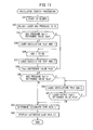
- step S 34 the laser oscillation test run 1 is executed under the first oscillation condition and the routine proceeds to step S 36 . Due to this, when the gas pressure difference Gd is large, a small laser output command P 1 is used to execute the laser oscillation test run 1 , so it is possible to prevent abnormal discharge at the time of the laser oscillation test run. On the other hand, when the gas pressure difference Gd is small, the laser oscillation test run 1 is omitted, so an efficient laser oscillation test run can be performed.
- step S 36 to step S 38 the laser oscillation test run 2 is repeated until the laser output Pa 2 becomes the second reference value Pt 2 .
- step S 42 the number N 2 of times of execution of the laser oscillation test run 2 is used to determine the estimated leak rate L 1 of the laser oscillator 2 .
- the relationship that the larger the number N 2 of times of execution, the larger the estimated leak rate L 1 is determined in advance by experiments, etc. and is stored in the memory. This relationship is used to determine the estimated leak rate L 1 .
- Gd>Gds the laser oscillation test run 1 is executed exactly one time.
- the laser oscillation test run 1 may also be repeated until the gas pressure difference Gd reaches the reference value Gds.
- the numbers N 1 and N 2 of times of execution of the laser oscillation test run 1 and the laser oscillation test run 2 may be used to determine the estimated leak rate L 1 .
- FIG. 10 is a flowchart which shows one example of the processing in this case. The same portions as shown in FIG. 9 are assigned the same reference notations.
- step S 43 it is determined if the gas pressure Gs 1 is larger than a predetermined reference value Gss.
- the reference value Gss is a threshold value for judging whether to perform the first initial operation. If the positive decision is made at step S 43 , the routine proceeds to step S 34 where the first initial operation is performed. Due to this, when the gas pressure Gs 1 is large, a small laser output command P 1 is used to execute the laser oscillation test run 1 , so it is possible to prevent abnormal discharge at the time of the laser oscillation test run.
- the control unit 5 performs control which uses the error between the laser output value and the laser output command as the basis to increase or decrease the power supplied to the laser power source 24 , that is, feedback control. Therefore, by effectively utilizing feedback and confirming the laser output before the completion of the oscillator startup processing, it is possible to more reliably obtain the desired laser output at the time of a laser radiation command. This point is considered in FIG. 11 .
- FIG. 11 is a modification of FIG. 10 . The same portions as shown in FIG. 10 are assigned the same reference notations.
- step S 45 in the same way as step S 43 , it is judged if the gas pressure Gs 1 is larger than the reference value Gss. If the positive decision is made at step S 45 , the routine proceeds to step S 46 , while if the negative decision is made, the routine proceeds to step S 42 .
- step S 46 a laser oscillation test run 3 is executed in accordance with a predetermined third oscillation condition. That is, laser oscillation is performed for exactly a predetermined time T 3 (third predetermined time) in accordance with the laser output command P 3 (third laser output command) and the duty command D 3 (third duty command) as pulse commands. The processing of this step S 46 is executed after effectively utilizing the feedback to the laser output command.
- the laser output command P 3 is, for example, set to a value larger than the laser output command P 2 .
- step S 47 it is judged if the detected laser output Pa 3 is smaller than a predetermined third reference value Pt 3 .
- the third reference value Pt 3 is, for example, set to a value larger than the second reference value Pt 2 . If the positive decision is made at step S 47 , the routine returns to step S 46 . Due to this, the laser oscillation test run 3 is repeated until the laser output Pa 3 reaches the reference value Pt 3 . If the negative decision is made at step S 47 , the routine proceeds to step S 42 .
- the gas pressure Gs 1 is larger than the reference value Gss, that is, when the laser gas is contaminated by a large amount of air at the time of start of the oscillator startup processing, the feedback is effectively utilized and the laser oscillation test run 3 is executed.
- the invention is not limited to this. It is also possible to effectively utilize the feedback after the second initial operation at all times and execute the laser oscillation test run 3 .
- the estimated leak rate L 1 of the laser oscillator 2 is determined from the laser output Pa 1 ( FIG. 4 , step S 15 ).
- the leak rate Lc which serves as a reference is determined in advance by another method and the estimated leak rate L 1 is determined from the leak rate Lc and the laser output Pa 1 .
- Ts 0 is subtracted from Ts 1 and the shutdown time Ts of the laser oscillator 2 (oscillator shutdown time) is calculated.
- the gas pressure difference Gd is divided by the oscillator shutdown time Ts to calculate the leak rate Lc (unit: Pa/hour).
- the power of the laser oscillator 2 (laser power source 24 ) is turned on and the oscillator powerup processing is ended. Due to this, the system becomes ready to start up the laser oscillator 2 .
- FIG. 13 is a flowchart which shows one example of oscillator startup processing according to a fourth embodiment.
- the processing of FIG. 13 is started when the oscillator powerup processing is ended.
- step S 61 to step S 64 the same processing as step S 11 to step S 14 of FIG. 4 is executed. That is, at step S 61 , the blower 3 is started up, at step S 62 , the laser gas pressure is adjusted to a predetermined value G 1 , at step S 63 , the laser oscillation test run is executed, and at step S 64 , the laser output Pa 1 at that time is stored in the memory.
- the leak rate Lc which is calculated by the oscillator powerup processing and the laser output Pa 1 are used as the basis to determine the estimated leak rate L 1 .
- a leak rate is determined from the laser output Pa 1 , and the average value of the determined leak rate and the leak rate Lc is calculated as the estimated leak rate.
- the estimated leak rate L 1 is displayed on the display unit 6 and the oscillator startup processing is ended.
- the gas pressure difference Gd which is measured during the shutdown time of the laser oscillator 2 is divided by the shutdown time Ts to calculate the reference leak rate Lc, then this leak rate Lc and laser output Pa 1 are used to calculate the estimated leak rate L 1 . Due to this, the leak rate Lc determined by simple calculation can be corrected by the leak rate based on the laser output, so a more accurate estimated leak rate L 1 can be determined.
- step S 55 instead of using the gas pressure difference Gd and oscillator shutdown time Ts to determine the leak rate Lc, it is also possible to determine the leak rate Lc from the gas pressure Gs 1 before startup of the laser oscillator 2 and the oscillator shutdown time Ts and, at step S 65 , calculate the estimated leak rate L 1 from this leak rate Lc and laser output Pa 1 . Instead of displaying the estimated leak rate L 1 , it is also possible to use the estimated leak rate L 1 as the basis to judge the quality of the hermetic seal of the laser gas container 1 and display a warning.
- FIG. 14 is a flowchart which shows a modification of FIG. 13 . The same portions as shown in FIG. 13 are assigned the same reference notations.
- the inverter power of the blower 3 becomes larger. The inverter power is monitored considering this point.
- the quality of the hermetic seal is judged without using the oscillator shutdown time Ts, so the oscillator powerup processing of FIG. 12 is not executed before the start of oscillator startup processing.
- the blower 3 is started up, then, at step S 67 , the power Eb of the inverter for driving the blower is stored in the memory.
- the inverter power Eb can be acquired by the control unit 5 (laser control unit 52 of FIG. 2 ).
- the laser gas pressure is adjusted to a predetermined value G 1
- step S 63 a laser oscillation test run is executed, at step S 64 , the laser output Pa 1 is stored in the memory, then, at step S 68 , in the same way as step S 17 of FIG. 5 , it is judged if the laser output Pa 1 is smaller than the reference value Pt 1 .
- step S 69 it is judged if the inverter power Eb is larger than a predetermined reference value Ebs.
- the reference value Ebs is the threshold value for judging the quality of the hermetic seal and is a value which is determined in advance by experiments, etc. If the positive decision is made at step S 69 , the routine proceeds to step S 70 , while if the negative decision is made, the routine passes step S 70 and ends the processing. At step S 70 , the display unit 6 displays a warning to indicate the effect that the hermetic seal of the laser gas container 1 is poor.
- FIG. 15 is another flow chart which shows a modification of FIG. 13 .
- the same portions as shown in FIG. 13 are assigned the same reference notations.
- the temperature (oscillator temperature) of the laser oscillator 2 is low, the laser output becomes lower. Considering this point, the oscillator temperature is monitored. That is, even if there is no problem in the hermetic seal, the laser output sometimes becomes low due to lowness of the oscillator temperature Tm. In this case, mistaken judgment of the hermetic seal being poor is prevented in the example of FIG. 15 .
- the quality of the hermetic seal is judged without using the oscillator shutdown time Ts, so the oscillator powerup processing of FIG. 12 is not executed before the start of the oscillator startup processing.
- FIG. 16 is a block diagram of a laser system 100 which corresponds to the processing of FIG. 15 .
- the control unit 5 is connected to a temperature detector 8 which detects the temperature of the laser oscillator 2 . It is possible to use a temperature switch or other temperature detector instead of a temperature detector 8 .
- step S 64 if storing the laser output Pa 1 at the time of the laser oscillation test run, the routine proceeds to step S 71 where the oscillator temperature Tm which is detected by the temperature detector 7 is stored in the memory.
- step S 72 it is judged if the laser output Pa 1 is smaller than the reference value Pt 1 . If the positive decision is made, the routine proceeds to step S 73 .
- step S 73 it is judged if the oscillator temperature Tm is higher than a predetermined reference value Tms.
- the reference value Tms is a threshold value for judging if it is possible to effectively judge the quality of the hermetic seal and can be determined in advance by experiments, etc.
- step S 73 the routine proceeds to step S 74 where the display unit 6 displays a warning. If the negative decision is made at step S 73 , the routine bypasses step S 74 and ends the processing. Due to this, when the oscillator temperature Tm is low (Tm ⁇ Tms), even when the laser output Pa 1 is smaller than the reference value Pt 1 , no warning is displayed, so it is possible to prevent the quality of the hermetic seal from being mistakenly judged.
- a gas pressure detector 33 is provided at the downstream side of the first heat exchanger 31 and the upstream side of the blower 30 .
- the gas pressure detector may be provided at another position as well.
- the laser gas pressure is adjusted to a predetermined value G 1 by controlling the feed device 13 and exhaust device 14 based on a value detected by the gas pressure detector 33 , the pressure adjusting part is not limited to this.
- the pressure control unit 51 can be configured in any way.
- the laser control unit 52 can be configured in any way. If estimating an extent of hermetic seal of the laser gas container 1 based on the detection value Pa 1 obtained by the laser detector 26 as the laser detector, the control unit 5 serving as the hermetic seal estimating part can be configured in any way.
- the estimated leak rate L 1 is determined by using the laser output Pa 1 detected at the time of the laser oscillation test run.
- the laser detector may also be configured by other than the laser detector 26 .
- the extent of the hermetic seal of the laser gas container 1 is estimated in accordance with the number N 1 of times of execution of the laser oscillation test run.
- the method of setting the predetermined value is not limited to this.
- the detected laser output Pa 1 and threshold value Pt 1 are compared to judge the quality of the hermetic seal.
- a laser oscillation test run 1 which outputs laser light in accordance with first oscillation condition (first initial operation) and a laser oscillation test run 2 which outputs laser light in accordance with second oscillation condition (second initial operation) are executed.
- first initial operation first oscillation condition
- second initial operation second oscillation condition
- the detection value Pa 2 of the laser light which is output by the second initial operation may be used as the basis to determine the estimated leak rate L 1 .
- the detection value GsO of the gas pressure when the command for turning off the power of the laser oscillator 2 is input is stored in gas pressure memory unit constituted by the memory of the control unit 5 .
- the gas pressure memory unit is not limited to this configuration.
- the pressure difference Gd between the gas pressure GsO stored in the gas pressure memory unit and the gas pressure Gs 1 detected after startup of the laser oscillator 2 is calculated by the control unit 5 , it is also possible to use a differential pressure gauge, etc. to detect the pressure difference Gd.
- the gas pressure Gs 1 detected before the start of the oscillator startup processing of the laser oscillator 2 is stored in the gas pressure memory unit constituted by the memory of the control unit 5 .
- the gas pressure memory unit is not limited to this in configuration.
- the third initial operation is executed by feedback control in accordance with the third oscillation condition.
- the time from when the power source of the laser oscillator 2 is turned off to when the startup of the laser oscillator 2 is started is calculated by the control unit 5 .
- the shutdown time calculating part is not limited to this configuration.
- the control unit 5 may be configured in any way.
- the inverter power Eb of the blower 3 and the reference value Ebs are compared in magnitude to estimate the extent of hermetic seal.
- another physical quantity which has a correlative relationship with the rotational operation of the blower 3 for example, the voltage, power, discharge pressure, suction pressure, etc. of the blower 3
- the temperature Tm of the laser oscillator 2 is detected by the temperature detector 8 .
- the gas pressure in a laser gas, container is made lower than atmospheric pressure, and at the time of startup of the laser oscillator, the extent of the hermetic seal of the laser gas container is estimated based on the detection value of the laser output. Therefore, it is possible to easily and accurately estimate the extent of the hermetic seal of the laser gas container.
Landscapes
- Physics & Mathematics (AREA)
- Electromagnetism (AREA)
- Engineering & Computer Science (AREA)
- Plasma & Fusion (AREA)
- Optics & Photonics (AREA)
- Lasers (AREA)
Abstract
Description
Claims (12)
Applications Claiming Priority (2)
| Application Number | Priority Date | Filing Date | Title |
|---|---|---|---|
| JP2013-042953 | 2013-03-05 | ||
| JP2013042953A JP5661834B2 (en) | 2013-03-05 | 2013-03-05 | Laser device capable of estimating the sealing property of a laser gas container |
Publications (2)
| Publication Number | Publication Date |
|---|---|
| US20160141823A1 US20160141823A1 (en) | 2016-05-19 |
| US9490602B2 true US9490602B2 (en) | 2016-11-08 |
Family
ID=51385651
Family Applications (1)
| Application Number | Title | Priority Date | Filing Date |
|---|---|---|---|
| US14/196,608 Expired - Fee Related US9490602B2 (en) | 2013-03-05 | 2014-03-04 | Laser system able to estimate hermetic seal of laser gas container |
Country Status (4)
| Country | Link |
|---|---|
| US (1) | US9490602B2 (en) |
| JP (1) | JP5661834B2 (en) |
| CN (1) | CN104037596B (en) |
| DE (1) | DE102014003158B4 (en) |
Families Citing this family (13)
| Publication number | Priority date | Publication date | Assignee | Title |
|---|---|---|---|---|
| JP6189883B2 (en) * | 2015-01-29 | 2017-08-30 | ファナック株式会社 | Gas laser device for determining composition ratio of laser gas |
| JP6010152B2 (en) * | 2015-02-16 | 2016-10-19 | ファナック株式会社 | Laser oscillator with blower |
| US9634455B1 (en) | 2016-02-16 | 2017-04-25 | Cymer, Llc | Gas optimization in a gas discharge light source |
| WO2017158694A1 (en) | 2016-03-14 | 2017-09-21 | ギガフォトン株式会社 | Laser apparatus and extreme ultraviolet light generation system |
| WO2017195244A1 (en) | 2016-05-09 | 2017-11-16 | ギガフォトン株式会社 | Laser device |
| JP6306659B1 (en) * | 2016-10-19 | 2018-04-04 | ファナック株式会社 | Beam distributor |
| JP7150711B2 (en) * | 2017-06-12 | 2022-10-11 | ギガフォトン株式会社 | LASER DEVICE, LASER DEVICE MANAGEMENT SYSTEM, AND LASER DEVICE MANAGEMENT METHOD |
| JP6629801B2 (en) * | 2017-09-05 | 2020-01-15 | ファナック株式会社 | Water leak detection system for laser equipment |
| CN110012047A (en) * | 2018-11-13 | 2019-07-12 | 阿里巴巴集团控股有限公司 | The monitoring method and device of container state, electronic equipment |
| CN112952536A (en) * | 2021-04-16 | 2021-06-11 | 北京镭海激光科技有限公司 | Seal off formula carbon dioxide laser pipe with leak gas detection surveys |
| JP7656188B2 (en) * | 2021-06-23 | 2025-04-03 | 日亜化学工業株式会社 | Semiconductor laser device |
| DE102022204308A1 (en) * | 2022-05-02 | 2023-11-02 | Trumpf Lasersystems For Semiconductor Manufacturing Gmbh | Indirectly monitored laser system |
| WO2024047873A1 (en) * | 2022-09-02 | 2024-03-07 | ファナック株式会社 | Control device, gas laser oscillator system, and control method |
Citations (14)
| Publication number | Priority date | Publication date | Assignee | Title |
|---|---|---|---|---|
| JPH02142558A (en) | 1988-08-17 | 1990-05-31 | Minnesota Mining & Mfg Co <3M> | Acetabular implant with rim-bearing on prothetic member for hip joint |
| JPH07176816A (en) | 1993-12-20 | 1995-07-14 | Daihen Corp | Starting of carbonic acid gas laser oscillator |
| JP2561510B2 (en) | 1988-04-12 | 1996-12-11 | 本田技研工業株式会社 | Vehicle wheel manufacturing method |
| JPH1065242A (en) | 1996-08-26 | 1998-03-06 | Matsushita Electric Ind Co Ltd | Gas laser oscillation device |
| JPH118426A (en) | 1997-06-17 | 1999-01-12 | Amada Co Ltd | Controller for laser oscillator |
| US6721344B2 (en) * | 2001-06-26 | 2004-04-13 | Komatsu Ltd. | Injection locking type or MOPA type of laser device |
| CN1837766A (en) | 2006-04-07 | 2006-09-27 | 梅特勒-托利多(常州)称重设备系统有限公司 | Leakage detection method for closed container |
| EP1816712A1 (en) | 2006-02-02 | 2007-08-08 | Fanuc Ltd | Gas laser oscillator |
| US20080043799A1 (en) | 2006-06-22 | 2008-02-21 | Fanuc Ltd | Gas laser oscillator |
| US20080304533A1 (en) | 2007-06-11 | 2008-12-11 | Fanuc Ltd | Startup method for gas laser unit and gas laser unit having startup function |
| US20090116521A1 (en) | 2007-11-06 | 2009-05-07 | Fanuc Ltd | Abnormality detection method for gas laser oscillator and gas laser oscillator for implementing the method |
| JP2011187526A (en) | 2010-03-05 | 2011-09-22 | Panasonic Corp | Laser oscillator |
| DE102011012821A1 (en) | 2010-04-02 | 2011-10-06 | Fanuc Corporation | Gas laser device |
| US20120006798A1 (en) * | 2009-03-12 | 2012-01-12 | Panasonic Corporation | Laser oscillator and laser machining apparatus |
Family Cites Families (3)
| Publication number | Priority date | Publication date | Assignee | Title |
|---|---|---|---|---|
| JPH02142558U (en) * | 1989-05-02 | 1990-12-04 | ||
| JP2561510Y2 (en) | 1997-01-13 | 1998-01-28 | 株式会社小松製作所 | Gas laser device |
| JP2006156634A (en) | 2004-11-29 | 2006-06-15 | Fanuc Ltd | Gas laser oscillator |
-
2013
- 2013-03-05 JP JP2013042953A patent/JP5661834B2/en not_active Expired - Fee Related
-
2014
- 2014-03-03 DE DE102014003158.6A patent/DE102014003158B4/en not_active Expired - Fee Related
- 2014-03-04 US US14/196,608 patent/US9490602B2/en not_active Expired - Fee Related
- 2014-03-05 CN CN201410078517.2A patent/CN104037596B/en not_active Expired - Fee Related
Patent Citations (18)
| Publication number | Priority date | Publication date | Assignee | Title |
|---|---|---|---|---|
| JP2561510B2 (en) | 1988-04-12 | 1996-12-11 | 本田技研工業株式会社 | Vehicle wheel manufacturing method |
| JPH02142558A (en) | 1988-08-17 | 1990-05-31 | Minnesota Mining & Mfg Co <3M> | Acetabular implant with rim-bearing on prothetic member for hip joint |
| JPH07176816A (en) | 1993-12-20 | 1995-07-14 | Daihen Corp | Starting of carbonic acid gas laser oscillator |
| JPH1065242A (en) | 1996-08-26 | 1998-03-06 | Matsushita Electric Ind Co Ltd | Gas laser oscillation device |
| JPH118426A (en) | 1997-06-17 | 1999-01-12 | Amada Co Ltd | Controller for laser oscillator |
| US6721344B2 (en) * | 2001-06-26 | 2004-04-13 | Komatsu Ltd. | Injection locking type or MOPA type of laser device |
| EP1816712A1 (en) | 2006-02-02 | 2007-08-08 | Fanuc Ltd | Gas laser oscillator |
| CN1837766A (en) | 2006-04-07 | 2006-09-27 | 梅特勒-托利多(常州)称重设备系统有限公司 | Leakage detection method for closed container |
| US20080043799A1 (en) | 2006-06-22 | 2008-02-21 | Fanuc Ltd | Gas laser oscillator |
| US20080304533A1 (en) | 2007-06-11 | 2008-12-11 | Fanuc Ltd | Startup method for gas laser unit and gas laser unit having startup function |
| CN101325305A (en) | 2007-06-11 | 2008-12-17 | 发那科株式会社 | Startup method for gas laser unit and gas laser unit having startup function |
| US20090116521A1 (en) | 2007-11-06 | 2009-05-07 | Fanuc Ltd | Abnormality detection method for gas laser oscillator and gas laser oscillator for implementing the method |
| US20120006798A1 (en) * | 2009-03-12 | 2012-01-12 | Panasonic Corporation | Laser oscillator and laser machining apparatus |
| JP2011187526A (en) | 2010-03-05 | 2011-09-22 | Panasonic Corp | Laser oscillator |
| DE102011012821A1 (en) | 2010-04-02 | 2011-10-06 | Fanuc Corporation | Gas laser device |
| US20110243177A1 (en) * | 2010-04-02 | 2011-10-06 | Fanuc Corporation | Gas laser device |
| JP2011228624A (en) | 2010-04-02 | 2011-11-10 | Fanuc Ltd | Gas laser apparatus |
| US20130315274A1 (en) | 2010-04-02 | 2013-11-28 | Fanuc Corporation | Gas laser device |
Also Published As
| Publication number | Publication date |
|---|---|
| CN104037596A (en) | 2014-09-10 |
| CN104037596B (en) | 2016-05-04 |
| JP2014170885A (en) | 2014-09-18 |
| DE102014003158A1 (en) | 2014-09-11 |
| US20160141823A1 (en) | 2016-05-19 |
| DE102014003158B4 (en) | 2018-09-13 |
| JP5661834B2 (en) | 2015-01-28 |
Similar Documents
| Publication | Publication Date | Title |
|---|---|---|
| US9490602B2 (en) | Laser system able to estimate hermetic seal of laser gas container | |
| JP4782887B1 (en) | Gas laser device | |
| US8486577B2 (en) | Fuel cell system | |
| US7551661B2 (en) | Gas laser oscillator | |
| US8897331B2 (en) | Lasing device | |
| US9671120B2 (en) | Thermal source instrument controlling device and air-conditioning system | |
| US20050195867A1 (en) | Laser unit | |
| US9653876B2 (en) | Gas laser apparatus for determining composition ratio of laser gas | |
| US20150372441A1 (en) | Gas laser oscillator capable of estimating sealability of gas container | |
| EP1816712B1 (en) | Gas laser oscillator | |
| EP1681750A1 (en) | Laser oscillator and method of estimating the lifetime of a pump light source | |
| JP2002208746A (en) | Gas control method and laser controller | |
| US20230296505A1 (en) | Apparatus and method | |
| EP1577990A2 (en) | Laser unit | |
| US9240665B2 (en) | Gas laser apparatus carrying out improved startup process | |
| CN103959430B (en) | The method that calibration includes the system of gas-discharge lamp and chiller | |
| JP5850969B2 (en) | Carbon dioxide laser oscillator capable of estimating the composition ratio of laser gas | |
| JP4676314B2 (en) | LASER OSCILLATOR AND METHOD FOR JUDGING FAILED COMPONENTS | |
| US20150214691A1 (en) | Gas laser system capable of maintaining laser gas state during power supply cutoff | |
| JP2012018979A (en) | Laser apparatus | |
| JP5810264B2 (en) | Laser oscillator | |
| JPS61229382A (en) | Laser oscillator | |
| JP2017059556A (en) | Laser oscillator |
Legal Events
| Date | Code | Title | Description |
|---|---|---|---|
| AS | Assignment |
Owner name: FANUC CORPORATION, JAPAN Free format text: ASSIGNMENT OF ASSIGNORS INTEREST;ASSIGNOR:NISHIO, AKIHIKO;REEL/FRAME:033342/0489 Effective date: 20140221 |
|
| AS | Assignment |
Owner name: FANUC CORPORATION, JAPAN Free format text: CORRECTIVE ASSIGNMENT TO CORRECT THE ASSIGNEE ADDRESS PREVIOUSLY RECORDED AT REEL: 033342 FRAME: 0489. ASSIGNOR(S) HEREBY CONFIRMS THE ASSIGNMENT;ASSIGNOR:NISHIO, AKIHIKO;REEL/FRAME:033719/0679 Effective date: 20140221 |
|
| STCF | Information on status: patent grant |
Free format text: PATENTED CASE |
|
| MAFP | Maintenance fee payment |
Free format text: PAYMENT OF MAINTENANCE FEE, 4TH YEAR, LARGE ENTITY (ORIGINAL EVENT CODE: M1551); ENTITY STATUS OF PATENT OWNER: LARGE ENTITY Year of fee payment: 4 |
|
| LAPS | Lapse for failure to pay maintenance fees |
Free format text: PATENT EXPIRED FOR FAILURE TO PAY MAINTENANCE FEES (ORIGINAL EVENT CODE: EXP.); ENTITY STATUS OF PATENT OWNER: LARGE ENTITY |
|
| STCH | Information on status: patent discontinuation |
Free format text: PATENT EXPIRED DUE TO NONPAYMENT OF MAINTENANCE FEES UNDER 37 CFR 1.362 |
|
| FP | Lapsed due to failure to pay maintenance fee |
Effective date: 20241108 |