US9488400B2 - System for managing lubricant levels in tandem compressor assemblies of an HVAC system - Google Patents
System for managing lubricant levels in tandem compressor assemblies of an HVAC system Download PDFInfo
- Publication number
- US9488400B2 US9488400B2 US14/293,099 US201414293099A US9488400B2 US 9488400 B2 US9488400 B2 US 9488400B2 US 201414293099 A US201414293099 A US 201414293099A US 9488400 B2 US9488400 B2 US 9488400B2
- Authority
- US
- United States
- Prior art keywords
- compressor
- state
- controller
- demand
- assembly
- Prior art date
- Legal status (The legal status is an assumption and is not a legal conclusion. Google has not performed a legal analysis and makes no representation as to the accuracy of the status listed.)
- Active, expires
Links
Images


Classifications
-
- F—MECHANICAL ENGINEERING; LIGHTING; HEATING; WEAPONS; BLASTING
- F25—REFRIGERATION OR COOLING; COMBINED HEATING AND REFRIGERATION SYSTEMS; HEAT PUMP SYSTEMS; MANUFACTURE OR STORAGE OF ICE; LIQUEFACTION SOLIDIFICATION OF GASES
- F25B—REFRIGERATION MACHINES, PLANTS OR SYSTEMS; COMBINED HEATING AND REFRIGERATION SYSTEMS; HEAT PUMP SYSTEMS
- F25B49/00—Arrangement or mounting of control or safety devices
- F25B49/02—Arrangement or mounting of control or safety devices for compression type machines, plants or systems
- F25B49/022—Compressor control arrangements
-
- F—MECHANICAL ENGINEERING; LIGHTING; HEATING; WEAPONS; BLASTING
- F25—REFRIGERATION OR COOLING; COMBINED HEATING AND REFRIGERATION SYSTEMS; HEAT PUMP SYSTEMS; MANUFACTURE OR STORAGE OF ICE; LIQUEFACTION SOLIDIFICATION OF GASES
- F25B—REFRIGERATION MACHINES, PLANTS OR SYSTEMS; COMBINED HEATING AND REFRIGERATION SYSTEMS; HEAT PUMP SYSTEMS
- F25B31/00—Compressor arrangements
- F25B31/002—Lubrication
- F25B31/004—Lubrication oil recirculating arrangements
-
- F—MECHANICAL ENGINEERING; LIGHTING; HEATING; WEAPONS; BLASTING
- F25—REFRIGERATION OR COOLING; COMBINED HEATING AND REFRIGERATION SYSTEMS; HEAT PUMP SYSTEMS; MANUFACTURE OR STORAGE OF ICE; LIQUEFACTION SOLIDIFICATION OF GASES
- F25B—REFRIGERATION MACHINES, PLANTS OR SYSTEMS; COMBINED HEATING AND REFRIGERATION SYSTEMS; HEAT PUMP SYSTEMS
- F25B31/00—Compressor arrangements
- F25B31/02—Compressor arrangements of motor-compressor units
-
- F—MECHANICAL ENGINEERING; LIGHTING; HEATING; WEAPONS; BLASTING
- F25—REFRIGERATION OR COOLING; COMBINED HEATING AND REFRIGERATION SYSTEMS; HEAT PUMP SYSTEMS; MANUFACTURE OR STORAGE OF ICE; LIQUEFACTION SOLIDIFICATION OF GASES
- F25B—REFRIGERATION MACHINES, PLANTS OR SYSTEMS; COMBINED HEATING AND REFRIGERATION SYSTEMS; HEAT PUMP SYSTEMS
- F25B2400/00—General features or devices for refrigeration machines, plants or systems, combined heating and refrigeration systems or heat-pump systems, i.e. not limited to a particular subgroup of F25B
- F25B2400/06—Several compression cycles arranged in parallel
-
- F—MECHANICAL ENGINEERING; LIGHTING; HEATING; WEAPONS; BLASTING
- F25—REFRIGERATION OR COOLING; COMBINED HEATING AND REFRIGERATION SYSTEMS; HEAT PUMP SYSTEMS; MANUFACTURE OR STORAGE OF ICE; LIQUEFACTION SOLIDIFICATION OF GASES
- F25B—REFRIGERATION MACHINES, PLANTS OR SYSTEMS; COMBINED HEATING AND REFRIGERATION SYSTEMS; HEAT PUMP SYSTEMS
- F25B2400/00—General features or devices for refrigeration machines, plants or systems, combined heating and refrigeration systems or heat-pump systems, i.e. not limited to a particular subgroup of F25B
- F25B2400/07—Details of compressors or related parts
- F25B2400/075—Details of compressors or related parts with parallel compressors
-
- F—MECHANICAL ENGINEERING; LIGHTING; HEATING; WEAPONS; BLASTING
- F25—REFRIGERATION OR COOLING; COMBINED HEATING AND REFRIGERATION SYSTEMS; HEAT PUMP SYSTEMS; MANUFACTURE OR STORAGE OF ICE; LIQUEFACTION SOLIDIFICATION OF GASES
- F25B—REFRIGERATION MACHINES, PLANTS OR SYSTEMS; COMBINED HEATING AND REFRIGERATION SYSTEMS; HEAT PUMP SYSTEMS
- F25B2500/00—Problems to be solved
- F25B2500/16—Lubrication
-
- F—MECHANICAL ENGINEERING; LIGHTING; HEATING; WEAPONS; BLASTING
- F25—REFRIGERATION OR COOLING; COMBINED HEATING AND REFRIGERATION SYSTEMS; HEAT PUMP SYSTEMS; MANUFACTURE OR STORAGE OF ICE; LIQUEFACTION SOLIDIFICATION OF GASES
- F25B—REFRIGERATION MACHINES, PLANTS OR SYSTEMS; COMBINED HEATING AND REFRIGERATION SYSTEMS; HEAT PUMP SYSTEMS
- F25B2600/00—Control issues
- F25B2600/01—Timing
-
- F—MECHANICAL ENGINEERING; LIGHTING; HEATING; WEAPONS; BLASTING
- F25—REFRIGERATION OR COOLING; COMBINED HEATING AND REFRIGERATION SYSTEMS; HEAT PUMP SYSTEMS; MANUFACTURE OR STORAGE OF ICE; LIQUEFACTION SOLIDIFICATION OF GASES
- F25B—REFRIGERATION MACHINES, PLANTS OR SYSTEMS; COMBINED HEATING AND REFRIGERATION SYSTEMS; HEAT PUMP SYSTEMS
- F25B2600/00—Control issues
- F25B2600/02—Compressor control
- F25B2600/025—Compressor control by controlling speed
- F25B2600/0251—Compressor control by controlling speed with on-off operation
-
- F—MECHANICAL ENGINEERING; LIGHTING; HEATING; WEAPONS; BLASTING
- F25—REFRIGERATION OR COOLING; COMBINED HEATING AND REFRIGERATION SYSTEMS; HEAT PUMP SYSTEMS; MANUFACTURE OR STORAGE OF ICE; LIQUEFACTION SOLIDIFICATION OF GASES
- F25B—REFRIGERATION MACHINES, PLANTS OR SYSTEMS; COMBINED HEATING AND REFRIGERATION SYSTEMS; HEAT PUMP SYSTEMS
- F25B2600/00—Control issues
- F25B2600/02—Compressor control
- F25B2600/025—Compressor control by controlling speed
- F25B2600/0252—Compressor control by controlling speed with two speeds
-
- F—MECHANICAL ENGINEERING; LIGHTING; HEATING; WEAPONS; BLASTING
- F25—REFRIGERATION OR COOLING; COMBINED HEATING AND REFRIGERATION SYSTEMS; HEAT PUMP SYSTEMS; MANUFACTURE OR STORAGE OF ICE; LIQUEFACTION SOLIDIFICATION OF GASES
- F25B—REFRIGERATION MACHINES, PLANTS OR SYSTEMS; COMBINED HEATING AND REFRIGERATION SYSTEMS; HEAT PUMP SYSTEMS
- F25B2700/00—Sensing or detecting of parameters; Sensors therefor
- F25B2700/03—Oil level
-
- F—MECHANICAL ENGINEERING; LIGHTING; HEATING; WEAPONS; BLASTING
- F25—REFRIGERATION OR COOLING; COMBINED HEATING AND REFRIGERATION SYSTEMS; HEAT PUMP SYSTEMS; MANUFACTURE OR STORAGE OF ICE; LIQUEFACTION SOLIDIFICATION OF GASES
- F25B—REFRIGERATION MACHINES, PLANTS OR SYSTEMS; COMBINED HEATING AND REFRIGERATION SYSTEMS; HEAT PUMP SYSTEMS
- F25B2700/00—Sensing or detecting of parameters; Sensors therefor
- F25B2700/21—Temperatures
- F25B2700/2106—Temperatures of fresh outdoor air
Definitions
- the present invention relates to compressors used in heating, ventilation, and air conditioning (HVAC) systems and, more particularly, to a system for managing lubricant levels in tandem compressor assemblies of an HVAC system.
- HVAC heating, ventilation, and air conditioning
- HVAC heating, ventilation, and air conditioning
- HVAC heating, ventilation, and air conditioning
- the compressors of a tandem assembly can be manifolded together allowing them to work simultaneously on the same heating or cooling circuit to deliver pressurized refrigerant to the HVAC system.
- oil used as a lubricant in the HVAC system is equalized between the compressors of the tandem assembly by an oil equalization system, such as piping between each compressor that maintains an equal oil level in the oil sumps.
- an oil equalization system such as piping between each compressor that maintains an equal oil level in the oil sumps.
- a controller of an HVAC system turns off both compressors to allow time for lubricant levels to equalize between the first and the second compressor when the tandem compressor assembly is transitioning from a partial load to a full load.
- FIG. 1 illustrates a first HVAC system having a first and second compressor assembly
- FIG. 2 shows a schematic of the first and second compressor assembly illustrated in FIG. 1 ;
- FIG. 3 shows a schematic of a control assembly operationally connected to a first and second compressor assembly
- FIG. 4 shows a portion of an HVAC system relative to an environmentally controlled space
- FIGS. 5A, 5B, and 5C show a flow chart of operations of a first method for managing lubricant levels in a multi-compressor assembly in an HVAC system
- FIG. 6 illustrates a second HVAC system having a first and second compressor assembly
- FIG. 7 shows a schematic of the first and second compressor assembly illustrated in FIG. 6 ;
- FIGS. 8A, 8B, 8C, and 8D show a flow chart of operations of a second method for managing lubricant levels in a multi-compressor assembly of an HVAC system
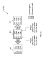
- FIGS. 9A, 9B, 9C, and 9D are tables showing compressor switching operations of a two-stage and a four-stage HVAC system having dual tandem assemblies.
- FIGS. 10A, 10B, 10C, and 10D are tables showing compressor switching operations of a two-stage and a four-stage HVAC system having a tandem compressor assembly operating in conjunction with a single 2-speed compressor.
- a refrigerant compressor assembly 100 may be configured to operate in a first heating, ventilation, and air conditioning (HVAC) system 1000 .
- the refrigerant compressor assembly 100 may comprise at least one tandem compressor assembly and at least one other compressor assembly.
- the refrigerant compressor assembly 100 comprises a first compressor assembly 101 , shown as a tandem compressor assembly, and a second compressor assembly 102 , also shown as a tandem compressor assembly.
- the refrigerant compressor assembly 100 may drive refrigerant, as a first heat transfer media, in direction t 1 through one or more flow line circuits containing heat transfer devices, e.g. condensers and evaporators.
- a first flow line circuit 107 shown in segments 107 a - d , may connect the first compressor assembly 101 to a first condenser portion 104 a of a condenser 104 , to a first expansion valve device 106 a of an expansion assembly 106 , and to a first evaporator portion 108 a of an evaporator 108 .
- a second flow line circuit 109 may connect the second compressor assembly 102 to a second condenser portion 104 b of the condenser 104 , to a second expansion valve device 106 b of the expansion assembly 106 , and to a second evaporator portion 108 b of the evaporator 108 .
- the condenser 104 and the evaporator 108 may comprise coils containing channels for the transfer of thermal energy between refrigerant flowing in the channels and the environment surrounding the coils.
- Each condenser 104 and evaporator 108 may be divided into the portions 104 a , 104 b and 108 a , and 108 b , respectively.
- Each portion of the condenser 104 and the evaporator 108 may be dedicated to one of the first compressor assembly 101 or the second compressor assembly 102 so that in some configurations only one portion of the evaporator 108 and the condenser 104 may be utilized in a cooling or heating cycle.
- portions of the condenser 104 or the evaporator 108 may comprise parts of the same integrated structure (e.g. one condenser with partitioned portions) or may comprise two separate structures that may be located in different physical locations (e.g. two condensers separately located).
- a control assembly 126 may be operationally connected to the refrigerant compressor assembly 100 to control operation of the first compressor assembly 101 and the second compressor assembly 102 .
- Other operations of the control assembly 126 may include, but not be limited to, sensing and measuring environmental data, receiving system data, to make calculations based on environmental and system data, reporting the status of the system, issuing commands based on timing functions, timers and clocks, and other operations readily apparent to persons of ordinary skill in the art.
- the first HVAC system 1000 may utilize a second heat transfer media in the cooling and heating cycle 110 .
- the second heat transfer media is air. Air may be pumped or blown by fluid moving devices, such as fan 103 and blower 105 , over the coils of the condenser 104 and the evaporator 108 , respectively, to facilitate the transfer of thermal energy between the refrigerant flowing in the channels and the environment surrounding the respective heat transfer device.
- the first HVAC system 1000 may be configured for refrigeration, cooling, and heating in the cooling or heating cycle 110 for maintaining a desired temperature profile in an enclosed space, such as a residential or commercial structure.
- each of the first compressor assembly 101 and the second compressor assembly 102 of the refrigerant compressor assembly 100 may comprise one or more compressor units.
- the first compressor assembly 101 may comprise a first compressor 112 and a second compressor 114 operationally connected in tandem for adjustment of the total heat transfer capacity of the first HVAC system 1000 .
- the second compressor assembly 102 may comprise a third compressor 113 and a fourth compressor 115 operationally connected in tandem for adjustment of the total heat transfer capacity of the first HVAC system 1000 .
- the first and second compressor assemblies 101 , 102 may comprise two or more compressor units operated in tandem, for example a three compressor system.
- the second compressor assembly 102 may comprise a single compressor assembly, for example a two-speed compressor.
- Each compressor of the first compressor assembly 101 and the second compressor assembly 102 may comprise the same or a different total capacity as compared to the other compressors.
- Each compressor of the first compressor assembly 101 and the second compressor assembly 102 may comprise a fixed capacity (i.e. one speed), a variable capacity, or a staged capacity (e.g. a two-stage capacity).
- the first compressor 112 and the second compressor 114 of the first compressor assembly 101 may be manifolded together such that the compressors 112 , 114 share one or more portions of flow line segments 107 a - d in the same heating or cooling cycle 110 .
- a first discharge line 116 of the first compressor 112 and a second discharge line 118 of the second compressor 114 may be connected by a first common discharge line 120 .
- a first suction line 117 of the first compressor 112 and a second suction line 119 of the second compressor 114 may be connected by a first common suction line 121 .
- Refrigerant pumped into the first compressor 112 via the first suction line 117 and the second compressor 114 via the second suction line 119 from the common suction line 121 may flow out from each respective discharge line 116 , 118 into the first common discharge line 120 .
- the third compressor 113 and the fourth compressor 115 of the second compressor assembly 102 may also be manifolded together in a tandem configuration to share one or more portions of flow line segments 109 a - d in the same heating or cooling cycle 110 .
- discharge lines 122 and 124 of the third and fourth compressors 113 and 115 are connected by a second common discharge line 137
- suction lines 123 and 125 are connected by a second common suction line 127 .
- Refrigerant pumped into the third compressor 113 and fourth compressor 115 via their respective suction lines 123 , 125 from the second common suction line 127 may flow out from each respective discharge line 122 , 124 into the second common discharge line 137
- the first common suction line 121 of the first compressor assembly 101 is configured to receive refrigerant flow from flow line segment 107 d . Refrigerant is then pumped by the first compressor assembly 101 through the first common discharge line 120 , which is configured to transfer refrigerant flow to the flow line segment 107 a.
- the second common suction line 127 of the second compressor assembly 102 is configured to receive refrigerant flow from flow line segment 109 d . Refrigerant is then pumped by the second compressor assembly 102 through the second common discharge line 137 , which is configured to transfer refrigerant flow to the flow line segment 109 a.
- each of the first compressor 112 and the second compressor 114 may comprise a first compressor sump 130 and a second compressor sump 132 , respectively.
- the third compressor 113 and the fourth compressor 115 of the second compressor assembly 102 may comprise sumps 134 , 136 respectively.
- Each compressor sump 130 , 132 , 134 , and 136 is configured as a collection vessel for lubricant 11 (shown as 11 a - d ), e.g. oil, used in the first HVAC system 1000 .
- oil and refrigerant may collect in the compressor sumps 130 , 132 , 134 , and 136 of the compressor(s) that is not operating.
- Oil levels may be equalized between the first compressor 112 and the second compressor 114 by a lubricant equalization system.
- the lubricant equalization system may comprise first tubing 138 that extends between the first compressor 112 and the second compressor 114 .
- the first tubing 138 provides a channel for movement of oil between compressors, which allows the amount of oil in each compressor 112 , 114 to equalize between the two compressors.
- Second tubing 140 shown extending between the third compressor 113 and the fourth compressor 115 may function in a similar manner to the first tubing 138 in allowing oil levels to equalize between the third compressor 113 and the fourth compressor 115 .
- Liquid refrigerant may condense and mix with the oil in the sump of the idle compressor (e.g. sump 132 ), diluting the oil available to the idle compressor, and reducing the lubricating quality of the oil present in the compressor.
- a control assembly 126 may be operationally connected to the refrigerant compressor assembly 100 .
- the control assembly 126 may further comprise a controller 128 operationally connected to the refrigerant compressor assembly 100 configured to control operation of the refrigerant compressor assembly 100 .
- control assembly 126 may further comprise the controller 128 operationally connected to the temperature detection assembly 129 .
- the temperature detection assembly 129 may be configured to detect the ambient temperature, which is the temperature outside an environmentally controlled space (shown as space 10 in FIG. 4 ).
- the controller 128 may be further configured to determine the sump superheat of the first and second compressor assemblies 101 , 102 based on the saturated suction temperature and the ambient temperature, which it is assumed is roughly equal to the temperature of the sump of an idle compressor.
- the temperature detection assembly 129 may comprise a temperature detection device, such as a thermostat 135 .
- the thermostat 135 may comprise a component of an outside unit 131 .
- the temperature detection device may comprise a digital sensor from part of a direct digital control (DDC) system, a zone sensor or other device configured to detect the ambient temperature.
- the sump superheat may be more accurately determined by adding a pressure transducer to the suction line of the idle compressor to measure suction pressure and measuring the temperature of the sump by direct measurement with for example a thermostat mounted on or near the sump.
- the outside unit 131 comprises the compressor assembly 100 and the condenser 104 , which is configured to receive flow of a second heat transfer media (e.g. air) from the fan assembly 103 .
- the outside unit 131 may be positioned outside of the walls 133 of the environmentally controlled space 10 to facilitate the transfer of heat between inside and outside the space 10 via refrigerant flow lines (e.g. flow line segments 107 b , 107 d and 109 b , 109 d ).
- a first method 2000 for managing lubricant levels in a tandem compressor assembly of an HVAC system may comprise the first HVAC system 1000 of FIGS. 1-4 configured to respond to measurement of an environmental condition, such as an ambient temperature at or below a mode transition temperature.
- the mode transition temperature may be determined based on sump superheat, which is the relationship between the environmental conditions, such as ambient temperature, and the saturated suction temperature.
- the sump superheat of a compressor is derived by subtracting the saturated sump temperature, which is approximately the saturated suction temperature, from the sump temperature, which in some embodiments is approximated as the ambient temperature. The higher the sump superheat the lower potential for refrigerant to condense as a liquid in the compressor sump.
- the mode transition temperature may be selected based on the conditions of operation of the first HVAC system 1000 , and may be based on the ambient temperature at which the sump superheat drops below about 20 degrees Fahrenheit.
- a low sump superheat may allow liquid refrigerant to collect in the sump of an idle compressor.
- Sump superheat for an idle compressor in a tandem assembly where the other compressor(s) is running may be in the range of 0 (zero) to 20 (twenty) degrees Fahrenheit for ambient temperatures below 65 (sixty-five) degrees Fahrenheit and in the 20 (twenty) degrees Fahrenheit and above for ambient temperatures above 65 degrees Fahrenheit.
- the mode transition temperature may be selected to be about 65 degrees Fahrenheit, with a tolerance of about plus or minus 2 (two) degrees Fahrenheit to account for environmental conditions and other known factors.
- the saturated suction temperature will equalize across all compressor sumps in the assembly.
- the sump temperature of the idle compressor, at this ambient temperature, is typically at or above 65 (sixty-five) degrees Fahrenheit, while the saturated suction temperature of the idle compressor assembly is typically about 45 (forty-five) degrees Fahrenheit. In this scenario, the sump superheat of the idle compressor is equal to or greater than about 20 (twenty) degrees Fahrenheit.
- the mode transition temperature may correspond to the operational state of the tandem compressor assembly, including the saturated suction temperature, where the sump superheat is at or above about 20 degrees Fahrenheit.
- the first method 2000 may comprise one or more operations for operating the first HVAC system 1000 in at least two modes based on the mode transition temperature.
- the first HVAC system 1000 may be operated in a first mode.
- the first mode may be configured to operate the first HVAC system 1000 with the objective of maximizing efficiency by operating one compressor in a tandem compressor assembly (e.g. the first compressor assembly 101 or the second compressor assembly 102 ) when there is only a partial load demanded on the first HVAC system 1000 .
- the tandem compressor assembly e.g. the first compressor assembly 101 or the second compressor assembly 102
- the first HVAC system 1000 may be operated in a second mode.
- the second mode may be configured to operate the first HVAC system 1000 with the objective of extending compressor life and system reliability.
- the mode transition temperature may be adjusted to accommodate environmental and operating conditions of the first HVAC system 1000 .
- the mode transition temperature may be affected by operating and environmental conditions, including but not limited to conditions of the air inside the environmentally controlled space, idling time of the compressors, and the air flow rate of the indoor blower 103 .
- the controller 128 may be configured to measure the real-time sump temperature and suction pressure to determine whether the first HVAC system 1000 should operate in the first mode or the second mode based on the measured ambient temperature.
- the first HVAC system 1000 may comprise a pre-demand state, where the first compressor 112 (referred to as “C 1 ” in FIG. 5 ), the second compressor 114 (referred to as “C 2 ” in FIG. 5 ), the third compressor 113 (referred to as “C 3 ” in FIG. 5 ), and the fourth compressor 115 (referred to as “C 4 ” in FIG. 5 ) are in an OFF state configured not deliver any load.
- the first compressor 112 referred to as “C 1 ” in FIG. 5
- the second compressor 114 referred to as “C 2 ” in FIG. 5
- the third compressor 113 referred to as “C 3 ” in FIG. 5
- the fourth compressor 115 referred to as “C 4 ” in FIG. 5
- the controller 128 of the first HVAC system 1000 may receive a command or respond to a triggering condition to initiate a multi-stage procedure where one or more of the compressors C 1 , C 2 , C 3 , or C 4 will be commanded to an “ON” state for meeting an initial demand.
- the controller 128 may operate the refrigerant compressor assembly 100 in three demand stages—referred to here as first demand stage Y 1 , second demand stage Y 2 , and third demand stage Y 3 , where each stage comprises a successively higher capacity to meet an increasing demand.
- the third demand stage Y 3 may correspond to the upper range of the full capacity of the refrigerant compressor assembly 100 .
- the full capacity of the HVAC system 1000 may comprise 100% of total available unit capacity.
- the first demand stage Y 1 may correspond to the lower range of capacity of the refrigerant compressor assembly 100 configured to change environmental conditions (e.g. temperature) of the controlled space.
- the capacity of the first demand stage Y 1 may comprise about 25% of total available unit capacity.
- the second demand stage Y 2 may comprises an intermediate capacity between the Y 1 capacity and the Y 3 capacity, for example about 60% of total available unit capacity. It will be understood by persons of ordinary skill in the art that the range of capacity from lowest to highest may depend on the specifications of the compressors and the efficiency of the HVAC system 1000 , among other factors.
- the operational capacity of each HVAC system 1000 may be tailored to meet the requirements of controlling the environment in the enclosed space.
- the first HVAC system 1000 may be configured to transition from a least a lower demand stage to a higher demand stage, where the refrigerant compressor assembly 100 outputs a lower capacity at the lower demand stage, and a higher capacity at the higher demand stage, for example from the first demand stage Y 1 to the second demand stage Y 2 or from Y 2 to Y 3 .
- a transition from one stage to another may comprise one or more operations configured to maintain lubricant levels in the sumps of the tandem compressors of the refrigerant compressor assembly 100 and lessen the risk of condensation of refrigerant in the sump of an idle tandem compressor.
- the transition from the lower demand stage to the higher demand stage may comprise operating at least a first tandem compressor assembly (e.g. the first compressor assembly 101 ) at a partial capacity with one compressor operated in an ON-state and the second compressor operated in an OFF-state followed by operating the tandem compressor assembly with both compressors in an OFF-state.
- the time that both compressors are in the OFF-state may be configured to allow lubricant levels (e.g. oil) to equalize between the two sumps of the first and second compressor.
- the transition from the lower demand stage to the higher demand stage may comprise operating at least both compressors of at least a first tandem compressor assembly in an OFF-state to both compressors of the first tandem compressor assembly in an ON-state.
- the lower demand stage may comprise a configuration of the refrigerant compressor assembly where all compressors are in an OFF-state, and there is no load demand on the HVAC system 1000 , e.g. the pre-demand state shown as operation 200 in FIG. 5A .
- each compressor C 1 , C 2 , C 3 , or C 4 will be referred to here and shown in the figures (i.e. FIGS. 5, 6, 9, and 10 ) with the equal sign notation.
- the OFF-state may include configurations where the compressor remains in a powered state, but is not delivering pressurized refrigerant to the first HVAC system 1000 .
- Each compressor in the ON-state may comprise a single fixed capacity, a variable capacity, or a staged capacity of two or more fixed capacities (e.g. a two-stage compressor).
- the selection of the capacity of each compressor in the ON-state may be adjusted to meet the desired load demand.
- the controller 128 may operate at a first demandstage capacity Y 1 with at least one compressor of a tandem compressor assembly of the first HVAC system 1000 in an ON-state.
- At least any one of the four compressors may be in an ON-state during operation 202 to meet the demand of the first demand stage Y 1 .
- the selection of which compressor (i.e. C 1 , C 2 , C 3 , or C 4 ) of the tandem compressor assembly (i.e. the first compressor assembly) to operate in the ON-state may depend on the individual capacity of each compressor in the tandem assembly and the desired load demand.
- both compressors C 3 and C 4 of the second compressor assembly 102 may remain in an OFF-state during operation 202 .
- the capacity of the first demand stage Y 1 may be configured to meet a relatively low demand that can be met by the operation of a single compressor (e.g. C 1 ). After a certain period of time operating the first HVAC system 1000 at Y 1 capacity, the controller 128 may determine that an increase in capacity is required to meet the demand on the first HVAC system 1000 .
- the controller 128 may receive a signal from the thermostat 135 that the ambient temperature is near, at, or above the mode transition temperature (referred to as “MTT” in FIGS. 5 and 8 ).
- MTT mode transition temperature
- the relationship of the ambient temperature to the MTT may allow the first HVAC system 1000 to determine whether to operate the first HVAC system 1000 in the first or the second mode.
- the controller 128 may operate the first HVAC system 1000 at the capacity of the second demand stage Y 2 in the first mode with at least one compressor of a second compressor assembly running.
- the Y 2 capacity may correspond to the middle range of the total operating capacity of the refrigerant compressor assembly 100 , i.e. a partial load.
- Compressor C 3 may be selected as the running compressor to meet the demand load of the Y 2 capacity, because the compressor is on an alternate flow line circuit, which utilizes alternate heat transfer devices, i.e. condenser and evaporator.
- running the first compressor 112 (corresponding to C 1 in FIG. 5 ) on the flow line circuit 107 in conjunction with the third compressor 113 (corresponding to C 3 in FIG. 5 ) on the flow line circuit 109 allows the first HVAC system 1000 to utilize both portions of the condenser 104 and evaporator 108 , portions 104 a , 104 b and 108 a , 108 b , respectively.
- the condenser 104 and the evaporator 108 increases the efficiency of the first HVAC system 1000 over using only one portion of each heat transfer device, because it increases the number of coils available for the transfer of thermal energy between the refrigerant and the environment. For example, if the first HVAC system 1000 were operated with C 1 and C 2 in an ON-state, where C 1 and C 2 share the same flow line circuit 107 , then the first HVAC system 1000 utilizes only half of the available coils of the condenser 104 and evaporator 108 , i.e. portions 104 a and 108 a , respectively.
- the controller 128 may determine that an increase in capacity is required to meet the demand on the first HVAC system 1000 .
- the controller 128 may transition the output capacity from the second demand stage Y 2 capacity, a partial load, to a third demand stage Y 3 capacity, a full load.
- the Y 3 capacity may require that both compressors of the tandem assemblies, e.g. C 1 and C 2 or C 3 and C 4 , of the refrigerant compressor assembly 100 be operated in an ON-state.
- the controller 128 may initiate a transition sequence of one or more operations to minimize the risk that the OFF compressors, i.e.
- the transition sequence may comprise turning OFF all compressors of at least one tandem compressor assembly while operating at least one alternate compressor assembly in an ON state.
- the first transition time period may be configured to allow sufficient time for lubricant to equalize between the two tandem-connected OFF compressors, i.e. C 1 and C 2 .
- the first transition time period may further be configured to minimize any reduction in capacity from the refrigerant compressor assembly 100 .
- only one compressor C 3 of the second compressor assembly 102 which is a tandem assembly, is running, which may, depending on the total available capacity of C 3 , result in a reduction delivered capacity by the first HVAC system 1000 .
- the controller 128 may increase the delivered capacity from C 3 to meet the desired load demands, and increase user comfort during the transition sequence.
- the second transition time period may be configured in a similar manner as the first transition time period—allowing time for oil equalization between tandem-connected compressors and minimizing any user discomfort due to reduced delivered capacity.
- the controller 128 may increase the delivered capacity from C 1 and C 2 to meet the desired load demands, and increase user comfort during the transition sequence.
- the first transition time period and the second transition time period may be about 5 (five) minutes.
- the transition time periods may be preset in the programming of the controller 128 or calculated by the controller 128 in an adjustable manner based on load demands, the available capacities of the refrigerant compressor assembly 100 during the respective transition operation environmental conditions, and estimations of user comfort.
- the first transition time period may be different from the second transition time period based on differences in the state of the first HVAC system 1000 and the environment during the two respective operations 208 and 209 .
- the Y 3 capacity may be configured to meet the highest anticipated demands on the first HVAC system 1000 , and may correspond to the upper range of the total operating capacity of the refrigerant compressor assembly 100 , e.g. operating all compressors in the ON-state or at or about their highest speed.
- the controller 128 may change operation of the refrigerant compressor assembly 100 from the operation 200 , where all compressors are in an OFF state, directly to operation 204 , where the controller 128 determines whether to operate the first HVAC system 1000 in the first mode or the second mode based on ambient temperature. In other embodiments, the controller 128 may change operation of the refrigerant compressor assembly 100 from the operation 200 directly to operation 210 , where the controller 128 operates the first HVAC system 1000 at the capacity of the third demand stage Y 3 at or near full capacity.
- the controller 128 may change operation of the first HVAC system 1000 from a full load at the Y 3 capacity (operation 210 ) to a partial load at the Y 2 capacity.
- the controller 128 in operation 212 , may receive a signal from the thermostat 135 that the ambient temperature is above the MTT.
- the controller 128 may initiate operation 206 , described above, to deliver a Y 2 capacity.
- the controller 128 may change operation of the first HVAC system 1000 from the capacity of the second demand stage Y 2 (operation 206 ) to the Y 1 capacity.
- the controller 128 may initiate operation 202 , described above, to deliver a Y 1 capacity.
- the controller 128 in either operation 204 (shown in FIG. 5A ) or in operation 212 (shown in FIG. 5B ), may receive a signal from the thermostat 135 that the ambient temperature is below the MTT.
- a lesser capacity e.g. a Y 1 capacity
- the second compressor assembly 102 of a second HVAC system 1002 may comprise a single two-speed compressor, referred to as the third compressor 113 ′, operated in conjunction with the first compressor assembly 101 , a tandem compressor assembly.
- the second HVAC system 1002 may include substantially similar or the same components as the first HVAC system 1000 , described in FIGS. 1-4 , including, but not limited to, the control assembly 126 and controller 128 , described herein and shown in FIGS. 1, 3, and 6 . Components of the second HVAC system 1002 that are substantially similar or the same will be referenced using the same reference numerals as those shown in FIGS. 1-4 for the first HVAC system 1000 .
- the third compressor 113 ′ may comprise the suction line 123 and the discharge line 122 . These lines 123 , 122 are tied into second condenser portion 104 b and second evaporator portion 108 b of the flow line circuit 109 (shown in the segments 109 a - d ), which is a separate circuit from the flow line circuit 107 , as described above in regard to FIGS. 1 and 2 .
- the third compressor 113 ′ may also comprise a sump 134 , which does not share lubricant with the other compressors 112 , 114
- a second method 3000 for managing lubricant levels of a tandem compressor assembly in an HVAC system may comprise the second HVAC system 1002 of FIGS. 6 and 7 .
- the second HVAC system 1002 may be configured to respond to measurement of an ambient temperature at or below the mode transition temperature (“MTT”), for example by use of temperature data from the temperature detecting assembly 129 and thermostat 135 , as shown and described in FIGS. 3 and 4 .
- MTT mode transition temperature
- the second HVAC system 1002 may be configured to operate in one or more modes based on the effect of ambient temperature on the sump superheat of an idle compressor. At temperatures above the MTT, the HVAC system 1002 may be operated in a third mode with the objective of maximizing efficiency.
- the third mode of the second method 3000 may include similar operations to the first mode of the first method 2000 (described in FIG. 5 ).
- the tandem compressor assembly i.e. the first compressor assembly 101 shown in FIGS. 6 and 7
- the tandem compressor assembly may be operated with one compressor ON and the other OFF, when there is only a partial load demanded on the HVAC system 1002 .
- all compressors in the tandem compressor assembly may be turned to an OFF-state to allow time for oil to equalize between the sumps of the tandem-connected compressors, before the compressors are resumed to at or near full capacity.
- An alternate compressor assembly may deliver an output load from the second HVAC system 1002 during the transition time period of the third mode.
- the second HVAC system 1002 may be operated in a fourth mode with the objective of extending compressor life, i.e. maximizing reliability.
- the fourth mode of the second method 3000 may include similar operations to the second mode of the first method 2000 (described in FIG. 5 ).
- the load demand may be switched—turning OFF the compressors of the tandem compressor assembly—to the alternate compressor assembly (i.e. the second compressor assembly 102 ) to avoid operating tandem compressor system (i.e. the first compressor assembly 101 shown in FIGS. 6 and 7 ) of the refrigerant compressor assembly 100 with one compressor in an ON-state and the other in an OFF-state.
- the OFF compressors of the tandem assembly may be jointly switched ON.
- the second HVAC system 1002 may comprise a pre-demand state, where the first compressor 112 (referred to as “C 1 ” in FIG. 8 ), the second compressor 114 (referred to as “C 2 ” in FIG. 8 ), and the third compressor 113 ′ (referred to as “C 3 ” in FIG. 8 ) are in an OFF-state configured not deliver any load.
- the controller 128 of the second HVAC system 1002 may receive a command or respond to a triggering condition to initiate a multi-stage procedure where one or more of the compressors C 1 , C 2 , or C 3 will be commanded to an ON-state for meeting an initial demand.
- the multi-stage procedure may comprise a first-stage Y 1 capacity corresponding to the lower range of the total operating capacity of the refrigerant compressor assembly 100 , a second-stage Y 2 capacity corresponding to the middle range of available capacity, and a third-stage Y 3 capacity corresponding to the upper range, including full load, of capacity available to the refrigerant compressor assembly 100 .
- the pre-demand state of operation 300 may comprise a lower demand stage relative to higher demand stages Y 1 , Y 2 , and Y 3 .
- the controller 128 may receive a signal from the thermostat 135 that the ambient temperature is near, at, or above the MTT.
- the relation of the ambient temperature to the MTT may allow the second HVAC system 1002 to determine whether to operate the second HVAC system 1002 in the third or the fourth mode.
- the controller 128 may operate at a first-stage capacity Y 1 in the third mode with at least one compressor of a tandem compressor assembly of the second HVAC system 1002 in an ON state.
- Compressor C 3 of the second compressor assembly 102 may remain OFF during operation 304 .
- the controller 128 may determine that an increase in capacity is required to meet the demand on the second HVAC system 1002 . From operation 304 , the controller 128 may operate the second HVAC system 1002 at a second-stage capacity Y 2 in the third mode with at least one compressor of the first compressor assembly 101 (e.g. C 1 ) running. As shown in FIG. 8A , the third compressor 113 ′ of the second compressor assembly 102 , which may be a two-stage compressor, may be operated at its lower speed (referred to as “LO” in FIG. 8 ) to meet the intermediate demand loads of the Y 2 capacity.
- LO lower speed
- the controller 128 may operate at a first-stage capacity Y 1 in the fourth mode with both compressors of the tandem compressor assembly of the HVAC system 1002 in an OFF state.
- Compressor C 3 of the second compressor assembly 102 may be operated at the HI speed setting.
- the controller 128 may receive a signal from the thermostat 135 that the ambient temperature is near, at, or above the MTT, which provides further indication whether the HVAC system 1002 should be operated in the third or fourth mode. In response to an indication that the ambient temperature is near, at, or above the MTT, the controller 128 may operate the second HVAC system 1002 according to operation 310 , described above, following operation 308 .
- the third compressor 113 ′ may be turned OFF. It may be advantageous in operation 310 to operate the third compressor 113 ′ at least at its LO speed in conjunction with compressor C 1 so that both available sets of coils from each portion of the condenser 104 and the evaporator 108 are utilized in the heat transfer cycle 110 . Operation of the second HVAC system 1002 in this manner may result in shorter operation times and save on energy costs, under some circumstances.
- the controller 128 may determine that an increase in capacity is required to meet the demand on the second HVAC system 1002 .
- the controller 128 may transition the output capacity to the third demand stage Y 3 capacity, a full load.
- the Y 3 capacity may require that both compressors of the tandem assembly, e.g. C 1 and C 2 , of the refrigerant compressor assembly 100 be operated in an ON-state.
- the controller 128 may initiate a transition sequence of one or more operations to minimize the risk that the OFF compressors, i.e. compressor C 2 , coming from operation 310 , will be started with low or diluted lubricant in the respective sumps 130 , 132 shown in FIG. 7 .
- the transition sequence may comprise turning OFF all compressors of at least one tandem compressor assembly while operating at least one alternate compressor assembly in an ON state.
- the third transition time period may be configured to allow sufficient time for lubricant to equalize between the two tandem-connected OFF compressors, i.e. C 1 and C 2 .
- the third transition time period may further be configured to minimize any reduction in capacity from the refrigerant compressor assembly 100 .
- the compressor C 3 i.e. the third compressor 113 ′ shown in FIGS. 6 and 7
- the compressor C 3 may be operated at its high speed (referred to as “HI” in FIG. 8 ) to meet load demands, and to reduce any user discomfort due to reduced capacity.
- the third transition time period is about five minutes.
- the third transition time period may be preset in the programming of the controller 128 or calculated by the controller 128 in an adjustable manner based on load demands, environmental conditions, and estimations of user comfort.
- the third compressor 113 ′ of the second compressor assembly 102 may be operated at about its highest speed to meet the full demand loads of the Y 3 capacity.
- the controller 128 may change operation of the refrigerant compressor assembly 100 from the operation 300 , where all compressors are in an OFF-state, directly to operation 308 , where the controller 128 determines whether to operate the second HVAC system 1002 in the first mode or the second mode based on ambient temperature. In other embodiments, the controller 128 may change operation of the refrigerant compressor assembly 100 from the operation 300 directly to operation 314 , where the controller 128 operates the second HVAC system 1002 at the third-stage Y 3 capacity at or near full capacity.
- the controller 128 may determine that a decrease in capacity may meet a lower demand on the second HVAC system 1002 , for example, because the temperature or other environmental conditions in the enclosed space is trending towards the desired temperature profile.
- the controller 128 may receive a signal from the thermostat 135 that the ambient temperature is near, at, or above the MTT, which provides further indication whether the second HVAC system 1002 should be operated in the third or fourth mode.
- the compressor C 3 (third compressor 113 ′) may be operated at its LO speed setting.
- the controller 128 may determine that a lower capacity, e.g. Y 1 capacity, may meet the load demand.
- a lower capacity e.g. Y 1 capacity
- the controller 128 may operate the second HVAC system 1002 at the Y 1 capacity according to the third mode, described previously.
- the controller 128 may operate the second HVAC system 1002 at the Y 1 capacity according to the fourth mode, described previously.
- the controller 128 in operation 308 (shown in FIG. 8A ), may receive a signal from the thermostat 135 that the ambient temperature is below the MTT.
- the controller 128 determines that a greater capacity is required, e.g. a Y 3 capacity, then the second HVAC system 1002 may be operated with all compressors ON (operation 314 ).
- the third compressor 113 ′ (C 3 in FIG. 8B ) may be operated at its HI speed setting to meet the required load demand.
- the controller 128 may change operation of the second HVAC system 1002 from a full load at Y 3 capacity (operation 314 ) to a partial load at Y 2 capacity.
- the controller 128 in operation 318 , may receive a signal from the thermostat 135 that the ambient temperature is below the MTT.
- the controller 128 may initiate operation 320 , described above, to deliver a Y 2 capacity.
- the controller 128 may determine during any operation that demand on the HVAC systems 1000 and 1002 has been satisfied (for example, the desired temperature profile has been achieved in the enclosed space) and may perform operations to decrease capacity, e.g. demand stages Y 3 to Y 2 to Y 1 , and subsequently turn OFF all compressors. In other embodiments, the controller 128 may change the operation of all compressors to an OFF state, as shown in operations 200 and 300 , without further transition to lower capacity stages.
- the controller 128 may comprise one or more processors and other well-known components.
- the controller 128 may further comprise two or more components operationally connected but located in separate in locations in the HVAC systems 1000 and 1002 , including operationally connected by wireless communications.
- the controller 128 may comprise a first controller unit located on an outside portion of the HVAC system (where the compressor and condenser may be), a second controller unit located on an inside portion (where the evaporator may be), a thermostat for monitoring environmental conditions (on a wall of an enclosed space), and a control unit accessible for user input (embodied on a hand-held wireless unit).
- the controller 128 may further comprise a timing function for measuring the time periods disclosed herein.
- HVAC systems utilizing multiple demand stages may be operated under the same or similar methods for managing lubricant levels of a tandem compressor assembly as the three stage system discussed above in FIGS. 1-8 .
- FIGS. 9A and 9B there is shown in a table format, by example, compressor switching operations for compressors in a dual tandem system having two demand stages—Y 1 , a lower demand stage, and Y 2 , a higher demand stage.
- FIGS. 9C and 9D show by example compressor switching operations of a dual tandem system having four demand stages—Y 1 , Y 2 , Y 3 , and Y 4 each successively comprising a higher capacity to meet an increasing load demand.
- tandem assembly 1 and tandem assembly 2 referenced in FIGS. 9A-9D may comprise the first compressor assembly 101 and the second compressor assembly 102 of the first HVAC system 1000 shown in FIGS. 1 and 2 .
- the controller 128 may transition the refrigerant compressor assembly 100 from the first demand stage Y 1 (i.e. the lower demand stage) to the second demand stage Y 2 (i.e. the higher demand stage).
- transition operations T 1 and T 2 may be utilized in a four stage system.
- transition operation T 1 may be utilized between the second demand stage Y 2 and the third demand stage Y 3
- transition operation may be utilized between the third demand stage Y 3 and the fourth demand stage Y 4 .
- the controller 128 may transition the refrigerant compressor assembly 100 from the pre-demand state Y 0 to the first demand stage Y 1 and to the second demand stage Y 2 .
- the lower demand stage may include the pre-demand state (e.g. operation 300 in FIG. 8A ) where all compressors are in an OFF-state.
- the refrigerant compressor assembly 100 is operated in a manner similar to operation 216 in FIG. 5C .
- Similar compressor switching operations may be utilized in the four stage system represented in FIG. 9D .
- compressors C 3 and C 4 are operated in the OFF-OFF configuration in the first demand stage Y 1 and transitioned to the ON-ON configuration in the second demand stage Y 2 .
- Compressors C 1 and C 2 are operated in the OFF-OFF configuration in the second demand stage Y 2 and transitioned to the ON-ON configuration in the third demand stage Y 3 .
- the load demand may be switched—turning OFF the compressors of the tandem assembly 1 —to the alternate tandem assembly 2 .
- tandem assembly 1 and the 2-speed compressor referenced in tables of FIGS. 10A-10D may comprise the first compressor assembly 101 and the second compressor assembly 102 of the second HVAC system 1002 shown in FIGS. 6 and 7 .
- the two-stage system referred to in FIG. 10A and the four-stage system referred to in FIG. 10C may include the same or similar transition operations from a lower demand stage, where tandem compressors are operated in an ON-OFF state to a higher demand stage, where both tandem compressors are operated in an ON-state, as those disclosed for operation of the three stage system in the first mode, shown in FIG. 8 .
- both compressors of the tandem assembly 1 are operated in the ON-state.
- the two-stage system referred to in FIG. 10B and the four-stage system referred to in FIG. 10D may include the same or similar transition operations from a lower demand stage, where the compressors of the tandem assembly 1 are operated in an OFF-OFF state to a higher demand stage, where both tandem compressors are operated in an ON-state, as those disclosed for operation of the three stage system in the second mode, shown in FIG. 8 .
- tandem compressors C 1 and C 2 are operated in the OFF-OFF configuration in the second demand stage Y 2 and transitioned to the ON-ON configuration in the third demand stage Y 3 .
- the speed of the 2-speed compressor C 3 may be adjusted in the first, second, third and fourth demand stages Y 1 , Y 2 , Y 3 , Y 4 of the two-stage and four stage system to meet the desired capacity during the transitions between stages.
Landscapes
- Engineering & Computer Science (AREA)
- Physics & Mathematics (AREA)
- Mechanical Engineering (AREA)
- Thermal Sciences (AREA)
- General Engineering & Computer Science (AREA)
- Air Conditioning Control Device (AREA)
Priority Applications (5)
| Application Number | Priority Date | Filing Date | Title |
|---|---|---|---|
| US14/293,099 US9488400B2 (en) | 2014-06-02 | 2014-06-02 | System for managing lubricant levels in tandem compressor assemblies of an HVAC system |
| CA2888764A CA2888764C (fr) | 2014-06-02 | 2015-04-21 | Mecanisme de gestion des niveaux de lubrifiant dans les dispositifs de compression en tandem d'un systeme cvca |
| EP15169821.4A EP2960600B1 (fr) | 2014-06-02 | 2015-05-29 | Système de gestion des niveaux de lubrifiant dans des ensembles de compresseurs en tandem d'un système cvca |
| US14/860,274 US10047965B2 (en) | 2014-06-02 | 2015-09-21 | System for managing lubricant levels in tandem compressor assemblies of an HVAC system |
| US15/343,258 US9989288B2 (en) | 2014-06-02 | 2016-11-04 | System for managing lubricant levels in tandem compressor assemblies of an HVAC system |
Applications Claiming Priority (1)
| Application Number | Priority Date | Filing Date | Title |
|---|---|---|---|
| US14/293,099 US9488400B2 (en) | 2014-06-02 | 2014-06-02 | System for managing lubricant levels in tandem compressor assemblies of an HVAC system |
Related Child Applications (2)
| Application Number | Title | Priority Date | Filing Date |
|---|---|---|---|
| US14/860,274 Continuation-In-Part US10047965B2 (en) | 2014-06-02 | 2015-09-21 | System for managing lubricant levels in tandem compressor assemblies of an HVAC system |
| US15/343,258 Continuation US9989288B2 (en) | 2014-06-02 | 2016-11-04 | System for managing lubricant levels in tandem compressor assemblies of an HVAC system |
Publications (2)
| Publication Number | Publication Date |
|---|---|
| US20150345848A1 US20150345848A1 (en) | 2015-12-03 |
| US9488400B2 true US9488400B2 (en) | 2016-11-08 |
Family
ID=53524546
Family Applications (2)
| Application Number | Title | Priority Date | Filing Date |
|---|---|---|---|
| US14/293,099 Active 2035-05-15 US9488400B2 (en) | 2014-06-02 | 2014-06-02 | System for managing lubricant levels in tandem compressor assemblies of an HVAC system |
| US15/343,258 Active 2034-07-20 US9989288B2 (en) | 2014-06-02 | 2016-11-04 | System for managing lubricant levels in tandem compressor assemblies of an HVAC system |
Family Applications After (1)
| Application Number | Title | Priority Date | Filing Date |
|---|---|---|---|
| US15/343,258 Active 2034-07-20 US9989288B2 (en) | 2014-06-02 | 2016-11-04 | System for managing lubricant levels in tandem compressor assemblies of an HVAC system |
Country Status (3)
| Country | Link |
|---|---|
| US (2) | US9488400B2 (fr) |
| EP (1) | EP2960600B1 (fr) |
| CA (1) | CA2888764C (fr) |
Cited By (3)
| Publication number | Priority date | Publication date | Assignee | Title |
|---|---|---|---|---|
| US20160161165A1 (en) * | 2014-12-04 | 2016-06-09 | Mitsubishi Electric Corporation | Air-conditioning system |
| US11639804B2 (en) | 2019-12-13 | 2023-05-02 | Trane International Inc. | Automated testing of HVAC devices |
| EP4166863A4 (fr) * | 2020-10-22 | 2024-01-03 | Gree Electric Appliances Inc Zhuhai | Procédé de commande de compresseur et appareil de commande et unité de climatisation modulaire |
Families Citing this family (8)
| Publication number | Priority date | Publication date | Assignee | Title |
|---|---|---|---|---|
| US10047965B2 (en) | 2014-06-02 | 2018-08-14 | Lennox Industries Inc. | System for managing lubricant levels in tandem compressor assemblies of an HVAC system |
| CA2941479C (fr) * | 2015-09-21 | 2019-01-29 | Lennox Industries Inc. | Systeme de gestion des niveaux de lubrifiant dans les assemblages de compresseur en tandem d'un systeme cvca |
| US10724752B2 (en) * | 2016-05-24 | 2020-07-28 | Gridpoint, Inc. | Methods and systems for automated HVAC testing |
| US10856449B2 (en) * | 2016-12-02 | 2020-12-01 | Dell Products L.P. | Dynamic cooling system |
| US10415856B2 (en) | 2017-04-05 | 2019-09-17 | Lennox Industries Inc. | Method and apparatus for part-load optimized refrigeration system with integrated intertwined row split condenser coil |
| CN107965870A (zh) * | 2017-11-24 | 2018-04-27 | 南京天加环境科技有限公司 | 一种能够有效控油的多联机空调系统 |
| CN110118422B (zh) * | 2018-02-07 | 2021-07-13 | 台达电子工业股份有限公司 | 冷气空调系统及其操作方法 |
| US20230375241A1 (en) * | 2022-05-20 | 2023-11-23 | Siemens Industry, Inc. | Multi-stage air handling unit for linear capacity output |
Citations (4)
| Publication number | Priority date | Publication date | Assignee | Title |
|---|---|---|---|---|
| US4506516A (en) | 1984-04-06 | 1985-03-26 | Carrier Corporation | Refrigeration unit compressor control |
| US20090084120A1 (en) | 2007-09-28 | 2009-04-02 | Hobart Brothers Company | Parked aircraft climate control system and method |
| US20100186433A1 (en) | 2009-01-23 | 2010-07-29 | Bitzer Kuhlmaschinenbau Gmgh | Scroll Compressors with Different Volume Indexes and Systems and Methods for Same |
| US7810353B2 (en) * | 2005-05-27 | 2010-10-12 | Purdue Research Foundation | Heat pump system with multi-stage compression |
Family Cites Families (5)
| Publication number | Priority date | Publication date | Assignee | Title |
|---|---|---|---|---|
| US5628201A (en) * | 1995-04-03 | 1997-05-13 | Copeland Corporation | Heating and cooling system with variable capacity compressor |
| US9726387B2 (en) * | 2013-07-02 | 2017-08-08 | Johnson Controls Technology Company | Hot gas reheat modulation |
| US10024591B2 (en) * | 2014-05-15 | 2018-07-17 | Lennox Industries Inc. | Sensor failure error handling |
| US9482454B2 (en) * | 2014-05-16 | 2016-11-01 | Lennox Industries Inc. | Compressor operation management in air conditioners |
| US10047965B2 (en) * | 2014-06-02 | 2018-08-14 | Lennox Industries Inc. | System for managing lubricant levels in tandem compressor assemblies of an HVAC system |
-
2014
- 2014-06-02 US US14/293,099 patent/US9488400B2/en active Active
-
2015
- 2015-04-21 CA CA2888764A patent/CA2888764C/fr active Active
- 2015-05-29 EP EP15169821.4A patent/EP2960600B1/fr active Active
-
2016
- 2016-11-04 US US15/343,258 patent/US9989288B2/en active Active
Patent Citations (4)
| Publication number | Priority date | Publication date | Assignee | Title |
|---|---|---|---|---|
| US4506516A (en) | 1984-04-06 | 1985-03-26 | Carrier Corporation | Refrigeration unit compressor control |
| US7810353B2 (en) * | 2005-05-27 | 2010-10-12 | Purdue Research Foundation | Heat pump system with multi-stage compression |
| US20090084120A1 (en) | 2007-09-28 | 2009-04-02 | Hobart Brothers Company | Parked aircraft climate control system and method |
| US20100186433A1 (en) | 2009-01-23 | 2010-07-29 | Bitzer Kuhlmaschinenbau Gmgh | Scroll Compressors with Different Volume Indexes and Systems and Methods for Same |
Non-Patent Citations (1)
| Title |
|---|
| European Patent Office, Communication for Application No. 15169821.4-1602 5 pages, Nov. 29, 2015. |
Cited By (4)
| Publication number | Priority date | Publication date | Assignee | Title |
|---|---|---|---|---|
| US20160161165A1 (en) * | 2014-12-04 | 2016-06-09 | Mitsubishi Electric Corporation | Air-conditioning system |
| US10047992B2 (en) * | 2014-12-04 | 2018-08-14 | Mitsubishi Electric Corporation | Air-conditioning system using control of number of compressors based on predetermined frequency ranges |
| US11639804B2 (en) | 2019-12-13 | 2023-05-02 | Trane International Inc. | Automated testing of HVAC devices |
| EP4166863A4 (fr) * | 2020-10-22 | 2024-01-03 | Gree Electric Appliances Inc Zhuhai | Procédé de commande de compresseur et appareil de commande et unité de climatisation modulaire |
Also Published As
| Publication number | Publication date |
|---|---|
| EP2960600B1 (fr) | 2022-03-30 |
| US20170051960A1 (en) | 2017-02-23 |
| CA2888764C (fr) | 2020-08-25 |
| EP2960600A1 (fr) | 2015-12-30 |
| US9989288B2 (en) | 2018-06-05 |
| CA2888764A1 (fr) | 2015-12-02 |
| US20150345848A1 (en) | 2015-12-03 |
Similar Documents
| Publication | Publication Date | Title |
|---|---|---|
| US9989288B2 (en) | System for managing lubricant levels in tandem compressor assemblies of an HVAC system | |
| US10760841B2 (en) | Variable fan speed control in HVAC systems and methods | |
| JP6257801B2 (ja) | 冷凍サイクル装置及び冷凍サイクル装置の異常検知システム | |
| US9562710B2 (en) | Diagnostics for variable-capacity compressor control systems and methods | |
| US10323862B2 (en) | Air conditioning unit having dynamic target condensing and evaporating values based on load requirements | |
| EP1536186B1 (fr) | Conditionneur d'air | |
| US10047965B2 (en) | System for managing lubricant levels in tandem compressor assemblies of an HVAC system | |
| JP5405076B2 (ja) | 空調冷凍システム | |
| CN104685303A (zh) | 一种用于使制冷负荷与压缩机容量匹配的方法 | |
| EP3299738A1 (fr) | Systeme de climatisation et d'alimentation en eau chaude | |
| JP6172702B2 (ja) | マルチ形空気調和システム | |
| EP3299734B1 (fr) | Systeme de climatisation et d'alimentation en eau chaude | |
| CA2941479C (fr) | Systeme de gestion des niveaux de lubrifiant dans les assemblages de compresseur en tandem d'un systeme cvca | |
| CN107894058B (zh) | 一种空调状态控制方法与装置 | |
| EP4148347A1 (fr) | Refroidisseur d'eau à compression segmenté, à passage unique et à compresseurs multiples | |
| WO2018179366A1 (fr) | Système à cycle de réfrigération et procédé de réglage de trafic de communication | |
| CN218600030U (zh) | 多级制冷系统 | |
| JP2007183030A (ja) | 連結式冷温水機、及びその運転方法 | |
| EP3299735B1 (fr) | Systeme de climatisation et d'alimentation en eau chaude | |
| KR102437449B1 (ko) | 냉각장치 및 그 제어방법 | |
| JP2005180819A (ja) | 空冷コンデンサ制御装置 | |
| KR101064372B1 (ko) | 멀티 공기조화기의 냉매 제어장치 | |
| KR20050086118A (ko) | 멀티 공기조화기의 냉매 제어장치 |
Legal Events
| Date | Code | Title | Description |
|---|---|---|---|
| AS | Assignment |
Owner name: LENNOX INDUSTRIES INC., TEXAS Free format text: ASSIGNMENT OF ASSIGNORS INTEREST;ASSIGNORS:HIM, AYLAN;HUNG, DER-KAI;MACKEY, DAVID;AND OTHERS;SIGNING DATES FROM 20140530 TO 20140602;REEL/FRAME:033006/0469 |
|
| STCF | Information on status: patent grant |
Free format text: PATENTED CASE |
|
| MAFP | Maintenance fee payment |
Free format text: PAYMENT OF MAINTENANCE FEE, 4TH YEAR, LARGE ENTITY (ORIGINAL EVENT CODE: M1551); ENTITY STATUS OF PATENT OWNER: LARGE ENTITY Year of fee payment: 4 |