US9468355B2 - Automatic dishwasher - Google Patents
Automatic dishwasher Download PDFInfo
- Publication number
- US9468355B2 US9468355B2 US14/187,350 US201414187350A US9468355B2 US 9468355 B2 US9468355 B2 US 9468355B2 US 201414187350 A US201414187350 A US 201414187350A US 9468355 B2 US9468355 B2 US 9468355B2
- Authority
- US
- United States
- Prior art keywords
- air
- fan
- heat pump
- automatic dishwasher
- outside
- Prior art date
- Legal status (The legal status is an assumption and is not a legal conclusion. Google has not performed a legal analysis and makes no representation as to the accuracy of the status listed.)
- Active, expires
Links
Images


Classifications
-
- A—HUMAN NECESSITIES
- A47—FURNITURE; DOMESTIC ARTICLES OR APPLIANCES; COFFEE MILLS; SPICE MILLS; SUCTION CLEANERS IN GENERAL
- A47L—DOMESTIC WASHING OR CLEANING; SUCTION CLEANERS IN GENERAL
- A47L15/00—Washing or rinsing machines for crockery or tableware
- A47L15/0018—Controlling processes, i.e. processes to control the operation of the machine characterised by the purpose or target of the control
- A47L15/0021—Regulation of operational steps within the washing processes, e.g. optimisation or improvement of operational steps depending from the detergent nature or from the condition of the crockery
- A47L15/0042—Desorption phases of reversibly dehydrogenated drying material, e.g. zeolite in a sorption drying system
-
- A—HUMAN NECESSITIES
- A47—FURNITURE; DOMESTIC ARTICLES OR APPLIANCES; COFFEE MILLS; SPICE MILLS; SUCTION CLEANERS IN GENERAL
- A47L—DOMESTIC WASHING OR CLEANING; SUCTION CLEANERS IN GENERAL
- A47L15/00—Washing or rinsing machines for crockery or tableware
- A47L15/42—Details
- A47L15/4291—Recovery arrangements, e.g. for the recovery of energy or water
-
- A—HUMAN NECESSITIES
- A47—FURNITURE; DOMESTIC ARTICLES OR APPLIANCES; COFFEE MILLS; SPICE MILLS; SUCTION CLEANERS IN GENERAL
- A47L—DOMESTIC WASHING OR CLEANING; SUCTION CLEANERS IN GENERAL
- A47L15/00—Washing or rinsing machines for crockery or tableware
- A47L15/42—Details
- A47L15/48—Drying arrangements
- A47L15/483—Drying arrangements by using condensers
-
- A—HUMAN NECESSITIES
- A47—FURNITURE; DOMESTIC ARTICLES OR APPLIANCES; COFFEE MILLS; SPICE MILLS; SUCTION CLEANERS IN GENERAL
- A47L—DOMESTIC WASHING OR CLEANING; SUCTION CLEANERS IN GENERAL
- A47L15/00—Washing or rinsing machines for crockery or tableware
- A47L15/42—Details
- A47L15/48—Drying arrangements
- A47L15/486—Blower arrangements
-
- A—HUMAN NECESSITIES
- A47—FURNITURE; DOMESTIC ARTICLES OR APPLIANCES; COFFEE MILLS; SPICE MILLS; SUCTION CLEANERS IN GENERAL
- A47L—DOMESTIC WASHING OR CLEANING; SUCTION CLEANERS IN GENERAL
- A47L15/00—Washing or rinsing machines for crockery or tableware
- A47L15/42—Details
- A47L15/48—Drying arrangements
- A47L15/488—Connections of the tub with the ambient air, e.g. air intake or venting arrangements
-
- Y—GENERAL TAGGING OF NEW TECHNOLOGICAL DEVELOPMENTS; GENERAL TAGGING OF CROSS-SECTIONAL TECHNOLOGIES SPANNING OVER SEVERAL SECTIONS OF THE IPC; TECHNICAL SUBJECTS COVERED BY FORMER USPC CROSS-REFERENCE ART COLLECTIONS [XRACs] AND DIGESTS
- Y02—TECHNOLOGIES OR APPLICATIONS FOR MITIGATION OR ADAPTATION AGAINST CLIMATE CHANGE
- Y02B—CLIMATE CHANGE MITIGATION TECHNOLOGIES RELATED TO BUILDINGS, e.g. HOUSING, HOUSE APPLIANCES OR RELATED END-USER APPLICATIONS
- Y02B30/00—Energy efficient heating, ventilation or air conditioning [HVAC]
- Y02B30/52—Heat recovery pumps, i.e. heat pump based systems or units able to transfer the thermal energy from one area of the premises or part of the facilities to a different one, improving the overall efficiency
-
- Y—GENERAL TAGGING OF NEW TECHNOLOGICAL DEVELOPMENTS; GENERAL TAGGING OF CROSS-SECTIONAL TECHNOLOGIES SPANNING OVER SEVERAL SECTIONS OF THE IPC; TECHNICAL SUBJECTS COVERED BY FORMER USPC CROSS-REFERENCE ART COLLECTIONS [XRACs] AND DIGESTS
- Y02—TECHNOLOGIES OR APPLICATIONS FOR MITIGATION OR ADAPTATION AGAINST CLIMATE CHANGE
- Y02B—CLIMATE CHANGE MITIGATION TECHNOLOGIES RELATED TO BUILDINGS, e.g. HOUSING, HOUSE APPLIANCES OR RELATED END-USER APPLICATIONS
- Y02B40/00—Technologies aiming at improving the efficiency of home appliances, e.g. induction cooking or efficient technologies for refrigerators, freezers or dish washers
-
- Y02B40/44—
Definitions
- the invention relates to an automatic dishwasher, in particular configured as a domestic dishwasher, having a wash tub providing a washing compartment, a condensation dryer for supplying a wash tub wall with outside air and a heat pump device for heating washing liquid.
- Automatic dishwashers of the aforementioned type are well known per se from the prior art. They have a wash tub which for its part provides a washing compartment. In the intended use case, the wash tub is used to hold the dishes to be cleaned.
- the washing compartment provided by the wash tub is accessible on the user's part by way of a loading aperture. This can be sealed so as to be fluid-tight by means of a pivotably designed dishwasher door.
- An automatic dishwasher has a spray device in the washing compartment to supply the dishes to be cleaned with washing liquid.
- This generally has two or three rotatably configured spray arms which in specified normal operation spray washing liquid conveyed by a circulating pump onto the dishes to be cleaned.
- DE 102011000042 A1 has disclosed a heat pump device for heating washing liquid, said device extracting heat from the outside air surrounding the automatic dishwasher for heating the washing liquid.
- Automatic dishwashers known from the prior art typically have a condensation dryer for drying dishes after the completion of specified normal cleaning.
- this dryer is used to supply a wash tub wall with outside air which leads to cooling of the wash tub wall with the result that moist air in the interior of the wash tub can condense inside on the wash tub wall that is cooled from outside.
- humidity is removed from the air in the wash tub, which leads to drying of the dishes that are still hot at the end of a specified normal continuous wash program.
- the present invention provides an automatic dishwasher comprising a wash tub, a condensation dryer, and a heat pump device.
- the wash tub includes a washing compartment
- the condensation dryer is adapted to supply outside air to a washtub wall
- the heat pump device is adapted to heat washing liquid.
- the heat pump device and the condensation dryer have a common fan.
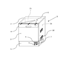
- FIG. 1 shows an automatic dishwasher with a condensation dryer in a schematic perspective view
- FIG. 2 shows the automatic dishwasher according to FIG. 1 in a schematic front view
- FIG. 3 shows an automatic dishwasher with a heat pump device in a schematic perspective view
- FIG. 4 shows the heat pump device of the automatic dishwasher according to FIG. 3 in a schematic plan view from above;
- FIG. 5 shows an automatic dishwasher according to the invention with a heat pump device in a heating phase in a schematic lateral view
- FIG. 6 shows an automatic dishwasher according to the invention with a heat pump device in a drying phase in a schematic lateral view
- FIG. 7 shows the automatic dishwasher according to FIG. 6 in a schematic front view.
- FIG. 8 shows a further configuration with the fan hydraulically connected upstream of the evaporator in a schematic lateral view
- FIG. 9 shows a further configuration of the airway switchover according to the invention with a heat pump device in a heating phase
- FIG. 10 shows a further configuration of the airway switchover according to the invention with a heat pump device in a drying phase.
- An aspect of the invention provide an automatic dishwasher including the condensation dryer and the heat pump device having a common fan.
- the condensation dryer known from the prior art has a fan. This is used in the drying case to suck in ambient air from outside and to direct it past the outside of a wash tub wall of the wash tub. The wash tub wall is thus cooled down, and in fact with the result that warm moist air inside the wash tub can condense inside on the cooled down wash tub wall.
- the automatic dishwasher has a heat pump device which likewise has a fan. This is used to suck in ambient air from outside and to direct it through an evaporator for the purpose of heat transfer. Heating of the washing liquid is achieved with the heat pump device, said device extracting heat from the outside air surrounding the automatic dishwasher for heating the washing liquid.
- the condensation dryer and the heat pump device have a common fan, that instead of a first fan for the condensation dryer and a second fan for the heat pump device, the automatic dishwasher thus has a single fan that is suitable for and intended to be used both as a drying fan for the condensation dryer and also as a heat pump fan for the heat pump device. Instead of two fans, the automatic dishwasher according to the invention has only a single fan.
- the fan provided according to the invention is hydraulically connected downstream of an evaporator of the heat pump device. Accordingly, outside air sucked in by the fan first passes the evaporator which is hydraulically connected upstream of the fan on the dishwasher side. When the heat pump device is switched on, the outside air is cooled in the evaporator. When the heat pump device is switched off, the outside air sucked in flows through the evaporator without a change in temperature.
- the second flow path meanwhile, is used during condensation drying after completion of a specified normal continuous cleaning program.
- the outside air sucked in via the fan is not directed out of the automatic dishwasher via the air outlets. Rather a change in direction of the outside air takes place inside the automatic dishwasher, as a result of which said air flows past the outside of a wash tub wall of the wash tub for the purpose of cooling said wall.
- a method for operating an embodiment of an automatic dishwasher equipped with a heat pump device is therefore proposed with the invention on the process side, in which method washing liquid is heated in a condenser in a heating phase and the outside air cooled for this purpose in an evaporator is discharged by means of a fan, and in which method the fan continues to be operated in a drying phase with a heat pump device that is otherwise switched off.
- An air switchover device is connected downstream of the fan in the flow direction of the outside air; by means of which device the outside air conveyed by the fan is optionally distributed to different flow paths according to a further feature of the invention. Distribution of the outside air conveyed by the fan to a first and/or a second flow path generates the advantages already explained previously.
- the fan can preferably be operated at a first speed and at a lower, in particular a significantly lower speed compared to the first speed, in particular the fan is speed-controllable.
- the fan is run during operation of the heat pump device, that is in a washing liquid heating phase, at the first speed, a volumetric flow of at least 50 m3/h being delivered. With the heat pump device switched off, that is during the first and/or the second drying phase, the fan is operated by comparison at reduced speed which ensures particularly energy-efficient operation of the automatic dishwasher.
- the door 3 has a faceplate 4 at the top in relation to the drawing plane according to FIG. 1 .
- a plinth area 5 which provides an air inlet 9 for outside air, that is to say ambient air 8 .
- a covering panel 12 arranged, for example, in the form of a worktop as can be seen in particular from the diagram according to FIG. 2 .
- the automatic dishwasher 1 has a condensation dryer 27 .
- This has a fan 7 which sucks in outside air 8 via the air inlet 9 .
- the outside air 8 that is sucked in is directed as air flow 10 past the wash tub wall 26 of the wash tub 25 and is re-released to the atmosphere surrounding the automatic dishwasher 1 at the top of the wash tub 25 as exhaust air 11 .
- the exhaust air 11 heated by flowing past the warm wash tub can be used in particular to preheat an adjacent kitchen worktop and to provide an air cushion which prevents water vapours that escape when the wash tub 3 is opened from condensing on the kitchen worktop.
- rinsing takes place as the conclusion of a cleaning program.
- the washing liquid and therefore also the dishes accommodated by the wash tub 25 are heated in the process to 55° C. for example.
- the surface tension of the washing liquid is reduced by adding a rinse aid.
- the washing liquid is pumped away at the end of rinsing.
- residual moisture can drip off or run off the dishes and the baskets for holding dishes that are located in the wash tub which is promoted by the low surface tension.
- the inherent heat of the dishes causes the water film still remaining to evaporate.
- the washing compartment air gradually becomes saturated with water vapour. If the washing compartment air is saturated, no further water can dry off the dishes and the baskets.
- the heat pump device 13 essentially has four components which are joined together hydraulically by way of a pipe system in which a working medium (refrigerant) flows.
- a working medium working medium
- the individual components are arranged such that it flows first through an evaporator 17 , then through a compressor 18 and finally through a condenser 19 . Subsequently, the refrigerant flows through an expansion device 20 (throttling point) before being fed back again to the evaporator 17 .
- liquid refrigerant is first sprayed into the evaporator 17 . Due to the low pressure of the refrigerant in the evaporator 17 , the refrigerant can evaporate at low temperatures. Subsequently, the compressor 18 sucks in the gaseous refrigerant at low pressure and compresses it to a high pressure. The refrigerant becomes hot in the process. As a result, the refrigerant contains approximately the sum of the evaporation energy and the drive energy of the compressor 18 . This energy is re-released inside the condenser 19 . This occurs due to condensing of the refrigerant. Finally, the liquid refrigerant is expanded to a low pressure using the throttling point 20 such that it can evaporate again in order to flow through the heat pump circuit another time.
- thermal energy must be made available to the evaporator and heat must be removed from the condenser.
- the evaporator obtains the thermal energy necessary to evaporate the refrigerant by cooling down supply air (i.e. ambient air) while the condenser releases the thermal energy to washing liquid of the dishwasher.
- the humidity in the air may condense and may be precipitated and collect in the evaporator 17 , in the air duct 22 and in the fan 16 .
- This accumulating condensate is collected in a drip pan provided for this purpose and is either discarded or used in a wash process.
- bacteria, germs and/or similar adhesions may develop because of the surfaces wetted with moisture. They may result in an undesirable odour formation which on the user's part is deemed to be unpleasant and consequently unfavourable.
- FIGS. 5, 6 and 7 show an automatic dishwasher 1 designed in a manner according to the invention, its special feature being that, instead of a first fan 7 for the condensation dryer 27 and a second fan 16 for the heat pump device 13 , only a single fan 21 is provided which as a common fan is provided for both the condensation dryer 27 and also the heat pump device 13 .
- the fan 16 provided by the heat pump device 13 can preferably be used as common fan 21 .
- An air switchover device 24 which in the embodiment shown has a twistably arranged air flap 23 , is connected downstream of the common fan 21 in the flow direction.
- a gate valve and/or comparable element may be provided instead of such an air flap 23 . It is crucial that by means of the air switchover device 24 the outside air 8 sucked in by the fan 21 can be directed past the wash tub wall 26 as air flow 10 and/or can be directed to the air outlet 15 as exhaust air 14 , as emerges in particular by looking at FIGS. 5 and 6 together.
- this configuration has the advantage that it is possible to dispense with a conventional drying fan. In addition to cost saving, this has the added advantage that there is more installation space available for the heat pump device 13 .
- a switchover of the airway can take place by means of the air switchover device 24 already described previously. This renders it possible in spite of drying fan 7 no longer being present, unlike in the prior art, to implement condensation drying in that the air conveyed in particular by fan 21 is conducted past the wash tub wall 26 as airflow 10 .
- the air duct 22 it is preferable to fit the air duct 22 with a pivotable air flap 23 .
- This air flap 23 may be constructed close to the wash tub wall 26 .
- the air flap 23 has a drive; for example a wax element, a servomotor, a shape memory metal and/or similar can be used for this. In this case, it may either be provided that only the one or the other airway or that both airways are supplied equally with outside air 8 .
- a volumetric flow of 50-150 m 3 /h, preferably 70 m 3 /h, is delivered by the fan during a heating phase of the heat pump device, while for condensation drying a lower volumetric flow (10-50 m 3 /h, preferably 30 m 3 /h) is typically adequate.
- Each of the volumetric flows can be achieved by adjusting an appropriate ratio of the two airways or by controlling the speed of the fan 21 .
- the fan 21 provided can also be hydraulically connected upstream of the evaporator 17 , as disclosed in FIG. 8 .
- the flap 23 When the flap 23 is closed, the heat pump device 13 is in the heating phase, the entire air flow being directed through the evaporator 17 .
- the flap 23 When the flap 23 is open (as illustrated in FIG. 8 ), a partial volumetric flow is directed over the wash tub wall for condensation drying in the drying phase. The second partial volumetric flow is used to dry the evaporator.
- the air switchover can also be implemented using several air flaps 23 . It is also conceivable to operate several air flaps 23 via only one actuator. This may be implemented, for example, by means of lever mechanisms known to the person skilled in the art.
- the washing liquid is heated by means of the heat pump device 13 .
- the compressor 18 of the heat pump device 13 is switched off when heating has taken place.
- the other wash phases such as intermediate rinsing or final rinsing, are implemented with or without heating phases.
- fan 21 is switched on resulting in drying of the fan 21 , the air duct 22 and the evaporator 17 .
- drying of the cleaned dishes by condensation drying then starts up, for the purpose of which the second airway is opened and the outside air 8 conveyed by the fan 21 is directed past the wash tub wall 26 as air flow 10 .
- both flow paths are opened simultaneously, drying of the dishes by condensation drying and drying of the evaporator 17 , fan 21 and air duct 22 can take place at the same time.
- the recitation of “at least one of A, B and C” should be interpreted as one or more of a group of elements consisting of A, B and C, and should not be interpreted as requiring at least one of each of the listed elements A, B and C, regardless of whether A, B and C are related as categories or otherwise.
- the recitation of “A, B and/or C” or “at least one of A, B or C” should be interpreted as including any singular entity from the listed elements, e.g., A, any subset from the listed elements, e.g., A and B, or the entire list of elements A, B and C.
Landscapes
- Washing And Drying Of Tableware (AREA)
Applications Claiming Priority (3)
| Application Number | Priority Date | Filing Date | Title |
|---|---|---|---|
| DE102013101861.0 | 2013-02-26 | ||
| DE102013101861.0A DE102013101861A1 (de) | 2013-02-26 | 2013-02-26 | Geschirrspülautomat, insbesondere Haushaltsgeschirrspülmaschine |
| DE102013101861 | 2013-02-26 |
Publications (2)
| Publication Number | Publication Date |
|---|---|
| US20140238450A1 US20140238450A1 (en) | 2014-08-28 |
| US9468355B2 true US9468355B2 (en) | 2016-10-18 |
Family
ID=50156715
Family Applications (1)
| Application Number | Title | Priority Date | Filing Date |
|---|---|---|---|
| US14/187,350 Active 2034-05-10 US9468355B2 (en) | 2013-02-26 | 2014-02-24 | Automatic dishwasher |
Country Status (3)
| Country | Link |
|---|---|
| US (1) | US9468355B2 (de) |
| EP (1) | EP2777471B1 (de) |
| DE (1) | DE102013101861A1 (de) |
Cited By (5)
| Publication number | Priority date | Publication date | Assignee | Title |
|---|---|---|---|---|
| US20170202424A1 (en) * | 2016-01-20 | 2017-07-20 | General Electric Company | Methods for Operating Dishwasher Appliances Having Energy Recovery Features |
| WO2019192887A1 (en) | 2018-04-02 | 2019-10-10 | Arcelik Anonim Sirketi | A washer with heat pump |
| EP3718459A1 (de) * | 2019-04-04 | 2020-10-07 | Miele & Cie. KG | Geschirrspülmaschine, insbesondere haushaltsgeschirrspülmaschine |
| WO2020249278A1 (en) * | 2019-06-14 | 2020-12-17 | Arcelik Anonim Sirketi | A dishwasher comprising a heat pump |
| US20230309781A1 (en) * | 2020-09-24 | 2023-10-05 | Sergei Kvitko | Dishwasher with a Cooling Function |
Families Citing this family (24)
| Publication number | Priority date | Publication date | Assignee | Title |
|---|---|---|---|---|
| DE102015113352A1 (de) | 2014-09-23 | 2016-03-24 | Fischerwerke Gmbh & Co. Kg | Befestigungssysteme mit feinteiligen Füllstoffen |
| WO2016089332A1 (en) * | 2014-12-03 | 2016-06-09 | Arcelik Anonim Sirketi | A heat pump dishwasher |
| CN105982631A (zh) * | 2015-02-04 | 2016-10-05 | 青岛海尔洗碗机有限公司 | 一种洗碗机冷凝干燥系统及冷凝干燥方法、洗碗机 |
| CN104825111B (zh) * | 2015-04-24 | 2017-11-10 | 佛山市顺德区美的洗涤电器制造有限公司 | 洗碗机干燥系统 |
| KR102124926B1 (ko) * | 2015-11-30 | 2020-07-07 | 삼성전자주식회사 | 송풍장치 및 이를 구비하는 식기 세척기 |
| DE102016103921A1 (de) | 2016-03-04 | 2017-09-07 | Miele & Cie. Kg | Geschirrspülmaschine |
| US9907451B2 (en) | 2016-05-09 | 2018-03-06 | Samsung Electronics Co., Ltd. | Dishwasher drying system with thermal storage heat exchanger |
| KR102373181B1 (ko) | 2017-05-26 | 2022-03-11 | 삼성전자주식회사 | 식기 세척기 |
| US20190133412A1 (en) * | 2017-11-06 | 2019-05-09 | Haier Us Appliance Solutions, Inc. | Heating assembly for a washing appliance |
| CN109938656B (zh) * | 2017-12-21 | 2022-03-29 | 青岛海尔洗碗机有限公司 | 一种热泵式洗碗机和控制方法 |
| TR201721398A2 (tr) * | 2017-12-25 | 2019-07-22 | Arcelik As | Isi pompali bulaşik maki̇nasi |
| TR201721402A2 (tr) * | 2017-12-25 | 2019-07-22 | Arcelik As | Isi pompali bulaşik maki̇nasi |
| CN108451468B (zh) * | 2018-03-26 | 2023-08-29 | 佛山市顺德区美的洗涤电器制造有限公司 | 洗涤电器 |
| US10506912B2 (en) * | 2018-05-16 | 2019-12-17 | Haier Us Appliance Solutions, Inc. | Dishwasher appliance with vent duct mixing |
| CN108937796A (zh) * | 2018-09-14 | 2018-12-07 | 佛山市顺德区美的洗涤电器制造有限公司 | 洗涤电器 |
| ES2756875A1 (es) * | 2018-10-25 | 2020-04-27 | Bsh Electrodomesticos Espana Sa | Evitación de la condensación del vapor de agua en la pared exterior de una máquina lavavajillas doméstica. |
| DE102020100433A1 (de) * | 2020-01-10 | 2021-07-15 | Miele & Cie. Kg | Geschirrspülmaschine, insbesondere Haushaltsgeschirrspülmaschine |
| CN114305282B (zh) | 2020-09-30 | 2025-12-12 | 博西华电器(江苏)有限公司 | 家用洗碗机 |
| DE102020212345A1 (de) | 2020-09-30 | 2022-03-31 | BSH Hausgeräte GmbH | Haushaltsgeschirrspülmaschine mit zumindest einem Luftauslass |
| US11672404B2 (en) * | 2020-10-07 | 2023-06-13 | Whirlpool Corporation | Dish treating appliance with an air supply circuit |
| US20230046683A1 (en) * | 2021-08-11 | 2023-02-16 | Whirlpool Corporation | Air barrier for door condensation |
| DE102023100906A1 (de) * | 2023-01-16 | 2024-07-18 | Illinois Tool Works Inc. | Spülmaschine mit wärmerückgewinnungsvorrichtung |
| DE102024202682A1 (de) * | 2024-03-21 | 2025-09-25 | BSH Hausgeräte GmbH | Geschirrspülmaschine mit einer Wärmepumpe |
| DE102024131132A1 (de) * | 2024-10-25 | 2026-04-30 | Miele & Cie. Kg | Trocknungseinrichtung, insbesondere Umlufttrocknungseinrichtung |
Citations (11)
| Publication number | Priority date | Publication date | Assignee | Title |
|---|---|---|---|---|
| DE3418304A1 (de) | 1984-05-17 | 1985-11-21 | Miele & Cie GmbH & Co, 4830 Gütersloh | Geschirrspuelmaschine |
| DE4230576A1 (de) | 1992-09-12 | 1994-03-17 | Licentia Gmbh | Geschirrspülmaschine mit einer Gebläseeinrichtung |
| DE4330456C1 (de) | 1993-09-08 | 1995-03-16 | Blomberg Werke Gmbh | Wäschetrockner |
| EP1447042A1 (de) | 2003-02-11 | 2004-08-18 | Whirlpool Corporation | Geschirrspülmaschine mit Trocknungsvorrichtung |
| WO2006080707A1 (en) | 2004-10-12 | 2006-08-03 | Lg Electronics, Inc. | Condensing apparatus of dish washer |
| JP2007125198A (ja) | 2005-11-04 | 2007-05-24 | Matsushita Electric Ind Co Ltd | 食器洗い乾燥機 |
| US20080264455A1 (en) * | 2007-04-25 | 2008-10-30 | Mark Edward Brewer | Humidity reducing exhaust duct for dishwasher |
| EP2047786A1 (de) | 2007-10-11 | 2009-04-15 | Panasonic Corporation | Geschirrspüler/-trockner |
| US20100043833A1 (en) * | 2008-08-21 | 2010-02-25 | Seong Ho Kim | Controlling method of dishwasher |
| US20100083991A1 (en) * | 2007-02-20 | 2010-04-08 | Electrolux Home Products Corporation N.V. | Drying system for a dishwasher |
| US20120167920A1 (en) | 2011-01-05 | 2012-07-05 | Miele & Cie. Kg | Method for carrying out a dishwashing program |
-
2013
- 2013-02-26 DE DE102013101861.0A patent/DE102013101861A1/de not_active Withdrawn
-
2014
- 2014-02-04 EP EP14401019.6A patent/EP2777471B1/de active Active
- 2014-02-24 US US14/187,350 patent/US9468355B2/en active Active
Patent Citations (13)
| Publication number | Priority date | Publication date | Assignee | Title |
|---|---|---|---|---|
| DE3418304A1 (de) | 1984-05-17 | 1985-11-21 | Miele & Cie GmbH & Co, 4830 Gütersloh | Geschirrspuelmaschine |
| DE4230576A1 (de) | 1992-09-12 | 1994-03-17 | Licentia Gmbh | Geschirrspülmaschine mit einer Gebläseeinrichtung |
| DE4330456C1 (de) | 1993-09-08 | 1995-03-16 | Blomberg Werke Gmbh | Wäschetrockner |
| EP1447042A1 (de) | 2003-02-11 | 2004-08-18 | Whirlpool Corporation | Geschirrspülmaschine mit Trocknungsvorrichtung |
| WO2006080707A1 (en) | 2004-10-12 | 2006-08-03 | Lg Electronics, Inc. | Condensing apparatus of dish washer |
| JP2007125198A (ja) | 2005-11-04 | 2007-05-24 | Matsushita Electric Ind Co Ltd | 食器洗い乾燥機 |
| US20100083991A1 (en) * | 2007-02-20 | 2010-04-08 | Electrolux Home Products Corporation N.V. | Drying system for a dishwasher |
| US20080264455A1 (en) * | 2007-04-25 | 2008-10-30 | Mark Edward Brewer | Humidity reducing exhaust duct for dishwasher |
| US20090095330A1 (en) * | 2007-10-11 | 2009-04-16 | Matsushita Electric Industrial Co., Ltd. | Dish washer/dryer |
| EP2047786A1 (de) | 2007-10-11 | 2009-04-15 | Panasonic Corporation | Geschirrspüler/-trockner |
| US20100043833A1 (en) * | 2008-08-21 | 2010-02-25 | Seong Ho Kim | Controlling method of dishwasher |
| US20120167920A1 (en) | 2011-01-05 | 2012-07-05 | Miele & Cie. Kg | Method for carrying out a dishwashing program |
| DE102011000042A1 (de) | 2011-01-05 | 2012-07-05 | Miele & Cie. Kg | Verfahren zum Durchführen eines Spülprogramms |
Cited By (5)
| Publication number | Priority date | Publication date | Assignee | Title |
|---|---|---|---|---|
| US20170202424A1 (en) * | 2016-01-20 | 2017-07-20 | General Electric Company | Methods for Operating Dishwasher Appliances Having Energy Recovery Features |
| WO2019192887A1 (en) | 2018-04-02 | 2019-10-10 | Arcelik Anonim Sirketi | A washer with heat pump |
| EP3718459A1 (de) * | 2019-04-04 | 2020-10-07 | Miele & Cie. KG | Geschirrspülmaschine, insbesondere haushaltsgeschirrspülmaschine |
| WO2020249278A1 (en) * | 2019-06-14 | 2020-12-17 | Arcelik Anonim Sirketi | A dishwasher comprising a heat pump |
| US20230309781A1 (en) * | 2020-09-24 | 2023-10-05 | Sergei Kvitko | Dishwasher with a Cooling Function |
Also Published As
| Publication number | Publication date |
|---|---|
| US20140238450A1 (en) | 2014-08-28 |
| EP2777471A3 (de) | 2015-01-07 |
| EP2777471A2 (de) | 2014-09-17 |
| DE102013101861A1 (de) | 2014-08-28 |
| EP2777471B1 (de) | 2017-11-22 |
Similar Documents
| Publication | Publication Date | Title |
|---|---|---|
| US9468355B2 (en) | Automatic dishwasher | |
| US8875721B2 (en) | Dishwasher with closed loop condenser | |
| EP3129541B1 (de) | Waschmaschine/trockner | |
| US10568487B2 (en) | Heating circulation type drying module of dishwasher | |
| AU2013407868B2 (en) | Dishwasher comprising heat pump system | |
| US20080283099A1 (en) | Energy-optimized cleaning machine | |
| US9510728B2 (en) | Reduced vapor dry systems and methods for dishwashers | |
| CN102286872A (zh) | 一种带热泵烘干和除湿功能的洗衣干衣机 | |
| US20200037845A1 (en) | Heating assembly for a washing appliance | |
| CN108523797A (zh) | 洗碗机及其控制方法 | |
| US11122959B2 (en) | Dishwashing appliance having an air-drying dehumidification assembly | |
| EP3731718B1 (de) | Wärmepumpengeschirrspüler | |
| CN109938656B (zh) | 一种热泵式洗碗机和控制方法 | |
| CN106618423A (zh) | 具干燥和预热功能的洗碗机 | |
| EP3226742B1 (de) | Wärmepumpengeschirrspüler | |
| CN207024022U (zh) | 具干燥和预热功能的洗碗机 | |
| WO2020064254A1 (en) | A heat pump dishwasher comprising an evaporator tray | |
| JP5837410B2 (ja) | 食器洗浄乾燥機 | |
| EP3731720B1 (de) | Wärmepumpengeschirrspüler | |
| US20250098932A1 (en) | Dish washer | |
| CN109938657B (zh) | 一种洗碗机及控制方法 | |
| TR2021021418A1 (tr) | Kurutma etki̇nli̇ği̇ arttirilan bi̇r bulaşik maki̇nesi̇ | |
| KR20140127189A (ko) | 기능가변제습기 |
Legal Events
| Date | Code | Title | Description |
|---|---|---|---|
| AS | Assignment |
Owner name: MIELE & CIE. KG, GERMANY Free format text: ASSIGNMENT OF ASSIGNORS INTEREST;ASSIGNORS:BERTRAM, ANDRE;DAHMS, TOBIAS;REILMANN, MICHAEL;REEL/FRAME:032286/0905 Effective date: 20140205 |
|
| STCF | Information on status: patent grant |
Free format text: PATENTED CASE |
|
| MAFP | Maintenance fee payment |
Free format text: PAYMENT OF MAINTENANCE FEE, 4TH YEAR, LARGE ENTITY (ORIGINAL EVENT CODE: M1551); ENTITY STATUS OF PATENT OWNER: LARGE ENTITY Year of fee payment: 4 |
|
| MAFP | Maintenance fee payment |
Free format text: PAYMENT OF MAINTENANCE FEE, 8TH YEAR, LARGE ENTITY (ORIGINAL EVENT CODE: M1552); ENTITY STATUS OF PATENT OWNER: LARGE ENTITY Year of fee payment: 8 |