US9464938B2 - Systems and methods for measuring polarization of light in images - Google Patents
Systems and methods for measuring polarization of light in images Download PDFInfo
- Publication number
- US9464938B2 US9464938B2 US14/174,652 US201414174652A US9464938B2 US 9464938 B2 US9464938 B2 US 9464938B2 US 201414174652 A US201414174652 A US 201414174652A US 9464938 B2 US9464938 B2 US 9464938B2
- Authority
- US
- United States
- Prior art keywords
- camera
- polarization
- scene
- images
- polarizing filter
- Prior art date
- Legal status (The legal status is an assumption and is not a legal conclusion. Google has not performed a legal analysis and makes no representation as to the accuracy of the status listed.)
- Active, expires
Links
- 230000010287 polarization Effects 0.000 title claims abstract description 137
- 238000000034 method Methods 0.000 title claims abstract description 73
- 238000000711 polarimetry Methods 0.000 claims abstract description 24
- 238000003384 imaging method Methods 0.000 claims description 47
- 239000011159 matrix material Substances 0.000 claims description 38
- 230000003287 optical effect Effects 0.000 claims description 26
- 238000012545 processing Methods 0.000 claims description 21
- 238000004364 calculation method Methods 0.000 claims description 10
- 238000004836 empirical method Methods 0.000 claims description 7
- 238000010586 diagram Methods 0.000 description 33
- 238000005259 measurement Methods 0.000 description 29
- 230000000694 effects Effects 0.000 description 10
- 238000012512 characterization method Methods 0.000 description 9
- 239000011521 glass Substances 0.000 description 8
- 238000002474 experimental method Methods 0.000 description 6
- 230000008569 process Effects 0.000 description 6
- 230000008859 change Effects 0.000 description 5
- 238000013459 approach Methods 0.000 description 4
- 230000006870 function Effects 0.000 description 4
- 230000007935 neutral effect Effects 0.000 description 4
- 230000008901 benefit Effects 0.000 description 3
- 238000001444 catalytic combustion detection Methods 0.000 description 3
- 238000011161 development Methods 0.000 description 3
- 230000018109 developmental process Effects 0.000 description 3
- 230000033001 locomotion Effects 0.000 description 3
- 230000000007 visual effect Effects 0.000 description 3
- RZVHIXYEVGDQDX-UHFFFAOYSA-N 9,10-anthraquinone Chemical compound C1=CC=C2C(=O)C3=CC=CC=C3C(=O)C2=C1 RZVHIXYEVGDQDX-UHFFFAOYSA-N 0.000 description 2
- 239000000853 adhesive Substances 0.000 description 2
- 230000001070 adhesive effect Effects 0.000 description 2
- 238000000576 coating method Methods 0.000 description 2
- 238000004891 communication Methods 0.000 description 2
- 238000000205 computational method Methods 0.000 description 2
- 230000004438 eyesight Effects 0.000 description 2
- 238000004519 manufacturing process Methods 0.000 description 2
- 239000000463 material Substances 0.000 description 2
- 230000007246 mechanism Effects 0.000 description 2
- 238000005096 rolling process Methods 0.000 description 2
- 230000009466 transformation Effects 0.000 description 2
- 238000002834 transmittance Methods 0.000 description 2
- 241000251468 Actinopterygii Species 0.000 description 1
- 238000012935 Averaging Methods 0.000 description 1
- 101150117538 Set2 gene Proteins 0.000 description 1
- 230000003213 activating effect Effects 0.000 description 1
- 230000004075 alteration Effects 0.000 description 1
- 239000006117 anti-reflective coating Substances 0.000 description 1
- 230000004888 barrier function Effects 0.000 description 1
- 230000005540 biological transmission Effects 0.000 description 1
- 239000011248 coating agent Substances 0.000 description 1
- 239000003086 colorant Substances 0.000 description 1
- 230000006835 compression Effects 0.000 description 1
- 238000007906 compression Methods 0.000 description 1
- 230000007423 decrease Effects 0.000 description 1
- 230000001419 dependent effect Effects 0.000 description 1
- 238000009795 derivation Methods 0.000 description 1
- 239000000428 dust Substances 0.000 description 1
- 230000005684 electric field Effects 0.000 description 1
- 238000005516 engineering process Methods 0.000 description 1
- 230000004313 glare Effects 0.000 description 1
- 230000036541 health Effects 0.000 description 1
- 230000008676 import Effects 0.000 description 1
- 238000009434 installation Methods 0.000 description 1
- 230000001343 mnemonic effect Effects 0.000 description 1
- 238000012986 modification Methods 0.000 description 1
- 230000004048 modification Effects 0.000 description 1
- 230000005855 radiation Effects 0.000 description 1
- 230000011514 reflex Effects 0.000 description 1
- 238000005070 sampling Methods 0.000 description 1
- 239000000779 smoke Substances 0.000 description 1
- XLYOFNOQVPJJNP-UHFFFAOYSA-N water Substances O XLYOFNOQVPJJNP-UHFFFAOYSA-N 0.000 description 1
Images


Classifications
-
- G—PHYSICS
- G01—MEASURING; TESTING
- G01J—MEASUREMENT OF INTENSITY, VELOCITY, SPECTRAL CONTENT, POLARISATION, PHASE OR PULSE CHARACTERISTICS OF INFRARED, VISIBLE OR ULTRAVIOLET LIGHT; COLORIMETRY; RADIATION PYROMETRY
- G01J4/00—Measuring polarisation of light
-
- G—PHYSICS
- G01—MEASURING; TESTING
- G01J—MEASUREMENT OF INTENSITY, VELOCITY, SPECTRAL CONTENT, POLARISATION, PHASE OR PULSE CHARACTERISTICS OF INFRARED, VISIBLE OR ULTRAVIOLET LIGHT; COLORIMETRY; RADIATION PYROMETRY
- G01J4/00—Measuring polarisation of light
- G01J4/04—Polarimeters using electric detection means
-
- B—PERFORMING OPERATIONS; TRANSPORTING
- B64—AIRCRAFT; AVIATION; COSMONAUTICS
- B64D—EQUIPMENT FOR FITTING IN OR TO AIRCRAFT; FLIGHT SUITS; PARACHUTES; ARRANGEMENT OR MOUNTING OF POWER PLANTS OR PROPULSION TRANSMISSIONS IN AIRCRAFT
- B64D47/00—Equipment not otherwise provided for
- B64D47/08—Arrangements of cameras
-
- B—PERFORMING OPERATIONS; TRANSPORTING
- B64—AIRCRAFT; AVIATION; COSMONAUTICS
- B64U—UNMANNED AERIAL VEHICLES [UAV]; EQUIPMENT THEREFOR
- B64U20/00—Constructional aspects of UAVs
- B64U20/80—Arrangement of on-board electronics, e.g. avionics systems or wiring
- B64U20/87—Mounting of imaging devices, e.g. mounting of gimbals
-
- G—PHYSICS
- G01—MEASURING; TESTING
- G01J—MEASUREMENT OF INTENSITY, VELOCITY, SPECTRAL CONTENT, POLARISATION, PHASE OR PULSE CHARACTERISTICS OF INFRARED, VISIBLE OR ULTRAVIOLET LIGHT; COLORIMETRY; RADIATION PYROMETRY
- G01J3/00—Spectrometry; Spectrophotometry; Monochromators; Measuring colours
- G01J3/02—Details
- G01J3/0205—Optical elements not provided otherwise, e.g. optical manifolds, diffusers, windows
- G01J3/0224—Optical elements not provided otherwise, e.g. optical manifolds, diffusers, windows using polarising or depolarising elements
-
- G—PHYSICS
- G01—MEASURING; TESTING
- G01J—MEASUREMENT OF INTENSITY, VELOCITY, SPECTRAL CONTENT, POLARISATION, PHASE OR PULSE CHARACTERISTICS OF INFRARED, VISIBLE OR ULTRAVIOLET LIGHT; COLORIMETRY; RADIATION PYROMETRY
- G01J3/00—Spectrometry; Spectrophotometry; Monochromators; Measuring colours
- G01J3/02—Details
- G01J3/0205—Optical elements not provided otherwise, e.g. optical manifolds, diffusers, windows
- G01J3/0237—Adjustable, e.g. focussing
-
- G—PHYSICS
- G01—MEASURING; TESTING
- G01J—MEASUREMENT OF INTENSITY, VELOCITY, SPECTRAL CONTENT, POLARISATION, PHASE OR PULSE CHARACTERISTICS OF INFRARED, VISIBLE OR ULTRAVIOLET LIGHT; COLORIMETRY; RADIATION PYROMETRY
- G01J3/00—Spectrometry; Spectrophotometry; Monochromators; Measuring colours
- G01J3/28—Investigating the spectrum
- G01J3/2823—Imaging spectrometer
- G01J2003/2826—Multispectral imaging, e.g. filter imaging
Definitions
- This disclosure generally relates to systems and methods for measuring the polarization of light in images.
- this disclosure relates to the use polarization and polarimetry for visually detecting objects of interest.
- polarimetry means the measurement and interpretation of the polarization of transverse waves, such as electromagnetic waves.
- Polarization and polarimetry can help users detect many objects of interest. For example, in a natural scene full of unpolarized light, smooth surfaces appear as linearly polarized light; those smooth surfaces often correspond to artifacts such as weapons or downed aircraft (which are frequently sought by the military) or foreign object damage (which most vehicle operators try to avoid). Polarization lets surveillance analysts' vision penetrate haze or the glare from surfaces like water or windows. Polarization enables military analysts to find submarines and mines or spot snipers hiding behind windows, and enables fishermen to find schools of fish. Polarization may also help civilian users measure weather parameters or assess the health of forests and crops.
- polarimetry and polarized imagery are rarely used. The reasons are cost, weight, and reliability. In general, it is not sufficient to put a single polarizing filter in front of a single camera. To measure polarization in an image and discern which parts of the image have different polarization than other parts, one must capture an image with at least two and usually three orientations of a polarizing filter. In prior art, this has meant: (1) an electrically controlled rotating filter mounted to a camera lens, (2) an electrically controlled filter wheel with several polarizing filters mounted at different angles, or (3) multiple cameras, each with a differently oriented polarizing filter. The cost, weight, and reliability penalties of these approaches have precluded most uses of polarimetry for images taken outside a laboratory.
- a filter wheel In the case of an electrically controlled rotating filter mounted to a camera lens, a filter wheel is configured to position polarizing filters with three or four different orientations in front of a single camera.
- a filter wheel is a fairly robust optical component with moving parts. It is about as heavy as a small camera used on a typical unmanned aerial vehicle (UAV). It occupies substantial volume. Having an electromechanical actuator, it is substantially less reliable than a digital camera and therefore reduces the reliability of an aircraft mission system.
- a rotating polarizer in front of a single camera is smaller than a filter wheel, but is still a robust optical component with moving parts. It substantially increases the weight of a small camera and may substantially increase its volume. It contains an electromechanical actuator, which reduces the reliability of an aircraft mission system.
- a system comprising multiple cameras facing the same direction, each with a differently oriented polarizer in front of it, imposes a small penalty to cost, weight, and reliability for each camera.
- using three or four cameras instead of one increases cost and weight and decreases reliability of the system.
- CCD charge-coupled device
- a charge-coupled device Such a camera would produce a digital image structured like a three- or four-color picture, but each “color” would correspond to the intensity of a different polarization. It is not clear that a pixel-by-pixel polarizing filter can be made economically.
- the camera does not allow actual color imaging (e.g., red, blue, and green) concurrent with the polarimetry.
- One such CCD chip is designed to output four “colors” (one for each polarization) rather than the usual three expected by image file formats. This poses technical and economic barriers to widespread acceptance.
- a moving vehicle e.g., an aerial vehicle
- the subject matter disclosed comprises systems capable of acquiring polarimetry data using a single camera with or without a polarizing filter.
- the data acquisition method comprises: (1) maneuvering the aircraft (or other vehicle) to orient the polarizing filter (and camera) in various directions when images are captured, (2) registering the various images to each other, and (3) computing polarimetry values (such as the Stokes parameters) for points of interest in the images.
- the data acquisition method comprises maneuvering the aircraft (or other vehicle) to orient the camera in various directions when images are captured and then performing the same operations (2) and (3) in a computer system. These methods measure the amount of polarization in a given scene by taking multiple camera images at different angles.
- One aspect of the subject matter disclosed herein is a method for determining the polarization of a scene, comprising: (a) placing a linear polarizing filter in the field of view of a camera comprising a lens and an array of sensors; (b) successively locating the camera and the linear polarizing filter in proximity to a single position, but at three different orientations for each of which a scene is within the field of view of the camera; (c) capturing first through third filtered images while the camera and the linear polarizing filter are at the three different orientations respectively; (d) transferring first through third sets of imaging data respectively representing the first through third filtered images from the camera to a computer system; and (e) computing a polarization of at least one point in the scene from the first through third sets of imaging data.
- the method may further comprise mounting the camera and the linear polarizing filter on a vehicle, wherein step (b) comprises maneuvering the vehicle, and/or registering the first through third sets of imaging data with respect to each other before performing step (e).
- step (e) comprises computing Stokes parameters.
- a system for acquiring images of a scene comprising: an unmanned vehicle; a camera onboard the unmanned vehicle, the camera comprising a lens and an array of sensors; a first linear polarizing filter disposed in front of at least a first portion of the array of sensors; an unmanned vehicle control system capable of controlling the unmanned vehicle to perform maneuvers, the unmanned vehicle control system comprising hardware and software, the software of the unmanned vehicle control system being configured to control the unmanned vehicle to position itself at or near a specified position for each of first, second and third occurrences and at first, second and third orientations which are different than each other, but which each place the scene within the field of view of the camera; and a camera control system disposed onboard the unmanned vehicle and capable of controlling the camera to capture images, the camera control system comprising hardware and software, the software of the camera control system being configured to control the camera to capture first, second and third images of a target scene during the first, second and third occurrences respectively and then outputting first, second
- the system may further comprise an imaging data processing system capable of processing imaging data, the imaging data processing system comprising hardware and software, the software of the imaging data processing system being configured to register the first, second and third sets of imaging data with respect to each other and compute polarization values for the imaged scene.
- an imaging data processing system capable of processing imaging data
- the imaging data processing system comprising hardware and software
- the software of the imaging data processing system being configured to register the first, second and third sets of imaging data with respect to each other and compute polarization values for the imaged scene.
- a further aspect is a method for determining the polarization of a scene, comprising: (a) characterizing the polarizing power of a camera comprising a lens and an array of sensors; (b) successively locating the camera in proximity to a single position, but at three different orientations for each of which a scene is within the field of view of the camera; (c) capturing first through third images while the camera is at the three different orientations respectively; (d) transferring first, second and third sets of imaging data representing the first through third captured images from the camera to a computer system; and (e) computing a polarization of at least one point in the scene from the first, second and third sets of imaging data.
- step (a) comprises determining first and second Mueller matrix elements.
- Another aspect is a system for acquiring images of a scene, comprising: an unmanned vehicle; a camera onboard the unmanned vehicle, the camera comprising a lens and an array of sensors; an unmanned vehicle control system capable of controlling the unmanned vehicle to perform maneuvers, the unmanned vehicle control system comprising hardware and software, the software of the unmanned vehicle control system being configured to control the unmanned vehicle to position itself at or near a specified position for each of first, second and third occurrences and at first, second and third orientations which are different than each other, but which each place the scene within the field of view of the camera; and a camera control system disposed onboard the unmanned vehicle and capable of controlling the camera to capture images, the camera control system comprising hardware and software, the software of the camera control system being configured to control the camera to capture first, second and third images of a target scene during the first, second and third occurrences respectively and then outputting first, second and third sets of imaging data respectively representing the first, second and third images.
- the system may further comprise an imaging data processing system capable of processing imaging data, the imaging data processing system comprising hardware and software, the software of the imaging data processing system being configured to register the first, second and third sets of imaging data with respect to each other and compute polarization values for the imaged scene based in part on stored data representing a characterization of the polarizing power of the camera.
- an imaging data processing system capable of processing imaging data
- the imaging data processing system comprising hardware and software
- the software of the imaging data processing system being configured to register the first, second and third sets of imaging data with respect to each other and compute polarization values for the imaged scene based in part on stored data representing a characterization of the polarizing power of the camera.
- Yet another aspect is a method for measuring polarization in light from a scene, comprising: (a) capturing successive images of a scene using a camera positioned in proximity to a single position and oriented at successive different orientation angles, wherein a set of matrices characterizing a polarizing power of the camera at different angles of incidence and different angles of orientation are known and there is no polarizing filter between an array of sensors of the camera and the scene; (b) registering the captured images with respect to each other; and (c) computing polarimetry values for light from at least one point of interest in the scene based on the registered captured images and the known matrices, wherein steps (b) and (c) are performed using a computer system comprising hardware and software.
- a further aspect of the subject matter disclosed herein is an empirical method for characterizing a polarizing power of a camera having a lens and a focal plane array of sensors at a specified angle of incidence of impinging light and a specified orientation angle, the method comprising: (a) providing a target that emits unpolarized light; (b) aiming the camera at the target without an intervening polarizing filter and with a portion of the target projected onto sensors in the center of the focal plane array; (c) capturing a reference image while the camera is in the state described in step (b); (d) calculating a set of reference pixel values for a set of pixels in the reference image which are adjacent to a pixel produced by a sensor in the center of the focal plane array; (e) aiming the camera at the target without an intervening polarizing filter and with a portion of the target projected onto sensors near an edge or corner of the focal plane array; (f) capturing a first image while the camera is in the state described in step (e); (g) calculating a first set
- the foregoing method may further comprise: (m) rotating the linear polarizing filter by 90°; (n) capturing a third image while the camera is in the state described in steps (e) and (m); and (o) calculating a third set of pixel values for a set of pixels in the third image which are adjacent to the pixel produced by the sensor near the edge or corner of the focal plane array, wherein in step (l), the second element of the matrix is calculated based on at least the set of reference pixel values and the second and third sets of pixel values.
- the empirical method may comprise computing an intensity coefficient based on the set of reference pixel values and the second and third sets of pixel values.
- the systems disclosed herein can provide one or more of the following benefits.
- the disclosed systems can have lower weight, lower cost, and (because no moving parts are added to the aircraft) higher reliability because they have neither a filter wheel nor a rotating polarizer.
- the disclosed systems can have lower weight and lower cost because it employs fewer cameras, and therefore has fewer electronic components and electrical connections, resulting in higher reliability.
- (3) In contrast to recent developments involving polarizing filters on a CCD, the disclosed systems require no development of new electronic fabrication processes, so the timeline and cost to make it available are better.
- Actual color imaging e.g., red, blue, and green
- the disclosed systems allow actual color imaging concurrent with polarimetry.
- Polarizing filters on a CCD do not allow this.
- the filter used in the systems disclosed herein is easy to remove in most embodiments, and therefore allows efficient unpolarized imaging with the same camera at the same resolution.
- Polarizing filters attached to a CCD are difficult or impossible to remove, so unpolarized imaging is only available with a second camera (costly) or by summing the intensities of neighboring pixels with different polarizations (lower photonic efficiency and lower resolution).
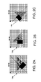
- FIGS. 1A, 1B and 1C are diagrams which respectively show a camera pixel grid overlying a target scene at respective orientations as the aircraft maneuvers to orient the camera.
- the dark spot at a corner of the camera pixel grid marks the same pixel in all images.
- the two-headed arrows indicate respective polarization angles corresponding to respective linear polarizing filter orientations.
- FIGS. 2A, 2B and 2C show images that will captured in the instances respectively shown in FIGS. 1A, 1B and 1C .
- FIG. 3 is a graph depicting the fact that perspective distorts polarizer orientation for pixels not at the center of an image.
- FIGS. 4A and 4B are diagrams representing top and side views of an idealized fixed-wing aircraft having a downward-facing camera.
- FIG. 5 is a diagram showing a flight path for the fixed-wing aircraft shown in FIGS. 4A and 4B , which flight path involves changes in heading to orient a polarizing filter mounted to the camera during three successive passes over a target.
- FIGS. 6A and 6B are diagrams representing side and front views of an idealized fixed-wing aircraft having a forward-facing camera with polarizing filter.
- FIG. 7 shows a flight path for the fixed-wing aircraft 20 shown in FIGS. 6A and 6B , which flight path involves changes in bank angle to orient the forward-facing camera with polarizing filter during flight along a straight path (i.e., the line of sight) directed toward a target.
- FIG. 8 is a diagram showing a flight path for the fixed-wing aircraft shown in FIGS. 6A and 6B , which flight path involves changes in heading and changes in bank angle to orient the forward-facing camera with polarizing filter during three successive passes through the same position lying along an initial line of sight to a target.
- FIG. 9 is a diagram showing a camera configuration in which a polarizing filter overlies a portion of a focal plane array of pixels inside the camera.
- FIG. 10 is a diagram representing a front view of the polarizing filter overlying a portion of a focal plane array. This is the view that would be visible if the camera were sectioned along a plane indicated by line 10 - 10 in FIG. 9 .
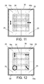
- FIG. 11 is a diagram representing a front view of two linear polarizing filters overlying respective halves of a focal plane array in accordance with one embodiment.
- the two linear polarizing filters are oriented perpendicular to each other.
- FIG. 12 is a diagram representing a front view of four polarizing filters overlying respective quadrants of a focal plane array. Three of the four polarizing filters are linear with different orientations, while the fourth polarizing filter is circular.
- FIG. 13 is a diagram representing a top view of a typical two-axis gimbal-mounted camera.
- FIG. 13A is a diagram representing a sectional view of the gimbal-mounted camera depicted in FIG. 13 .
- the gimbal is sectioned along a plane indicated by line 13 A- 13 A in FIG. 13 .
- FIG. 14 is a diagram representing a top view of a gimbal-mounted camera designed to facilitate changing the orientation of a polarizing filter attached to the camera.
- FIG. 14A is a diagram representing a sectional view of the gimbal-mounted camera depicted in FIG. 14 .
- the gimbal is sectioned along a plane indicated by line 14 A- 14 A in FIG. 14 .
- FIG. 14B is a diagram representing a sectional view of the gimbal-mounted camera after it has been rotated about the former gimbal elevation axis by 90°.
- FIG. 15 is a diagram representing a side view of an unmanned aerial vehicle having a gimbaled camera in a ball turret.
- FIG. 16 is a diagram representing a side view of an unmanned aerial vehicle having a gimbaled camera in and a polarizing filter applied on a ball turret to polarize a portion of the camera's field of regard.
- FIGS. 17A and 17B are diagrams which respectively show no polarization when light strikes glass at perpendicular incidence ( FIG. 17A ) and stronger reflection of s-polarized light at oblique incidence which increases p-polarized light in the transmitted beam ( FIG. 17B ).
- FIG. 19 is a diagram showing different polarization of light passing through a lens at different angles, corresponding to different positions of an object image on a focal plane array. Ellipse eccentricity shows the degree of polarization; ellipse orientation shows the polarization direction.
- FIGS. 19A through 19C are diagrams which respectively show different intensities of a scene object at different pixel positions which reveal its polarization (line width indicates intensity) for vertically polarized light ( FIG. 19A ), horizontally polarized light ( FIG. 19B ), and unpolarized light ( FIG. 19C ).
- FIG. 20A is a diagram showing a sectional view of an untilted lens and a lens tilted at angle ⁇ . These lenses are sectioned along a plane indicated by line 20 A- 20 A in FIG. 20B .
- FIG. 20B is a diagram showing front views of the lenses depicted in FIG. 20A and other lenses tilted at different orientations ⁇ .
- FIG. 20C is a diagram representing object images projected onto a focal plane array mounted coaxially with the lenses depicted in FIG. 20B .
- the angle ⁇ corresponds to angular position about the center of the focal plane.
- FIG. 21A is a diagram which shows that light parallel to a lens axis is not polarized at the center of lens and only weakly polarized at the edge of lens.
- FIG. 21B is a diagram which shows that light arriving at a large angle incurs stronger polarization at all points on the lens. (The degree of polarization varies slightly across the lens surface; only the center beam is shown.)
- FIG. 22 is a diagram showing the basic arrangement of a typical inner focus-type lens system.
- FIG. 23 is a diagram showing a sectional view of a focal plane array in a typical CCD.
- FIG. 24 is a diagram showings an experimental setup for characterizing a camera having a CCD.
- FIG. 26 is a diagram showing three loops of a flight path for a fixed-wing aircraft of the type shown in FIGS. 4A and 4B , except that the polarizing filter has been removed from the fixed downward-facing camera.
- the aircraft performs three maneuvers to bank the camera at bank angles of 45° west, 45° northwest, and 45° north of level while flying directly over a target.
- FIG. 27 is a block diagram identifying major components of a polarimetric data acquisition system in accordance with one embodiment.
- the system for acquiring polarization values for an imaged target comprises: an aircraft; an onboard navigation and control system capable of flying to a three-dimensional position (e.g., longitude, latitude and altitude) and later returning the aircraft to approximately the same position at least twice, and also capable of measuring the aircraft orientation at the position and setting the aircraft in a different selected orientation when it returns to the same position; an onboard camera having a known orientation with respect to the aircraft; an onboard linear polarizing filter having a known, fixed orientation with respect to the camera; an onboard control system capable of controlling the camera to capture images when the aircraft arrives at the selected position with one of the selected orientations; a computer (onboard or on the ground) programmed to register the images and compute polarization values for the imaged target; and means for transferring camera images to the computer.
- a three-dimensional position e.g., longitude, latitude and altitude
- an onboard linear polarizing filter having a known, fixed orientation with respect to the camera
- an onboard control system capable of controlling the
- the major process steps comprise: (a) flying the aircraft toward a position from which a target is in the camera's field of view; (b) before arriving at the position, orienting the aircraft to a first aircraft orientation corresponding to a first filter orientation about the line of sight to the target; (c) capturing a first image of the target while the aircraft is at the position and in the first aircraft orientation; (d) flying the aircraft toward the same position again; (e) before arriving at or near the position a second time, orienting the aircraft to a second aircraft orientation corresponding to a second filter orientation about the line of sight to the target; (f) capturing a second image of the target while the aircraft is at or near the position and in the second aircraft orientation; (g) flying the aircraft toward the same position again; (h) before arriving at or near the position a third time, orienting the aircraft to a third aircraft orientation corresponding
- the polarizer typically has three different orientations relative to the target.
- the circular polarization is zero, so that only linear polarization is of interest.
- the system user wants to know how much of the light from the target is polarized and how much is unpolarized, and what is the orientation of the polarized light.
- polarization is not only linear, but also includes circular components. Most of the embodiments disclosed in detail herein ignore circular polarization for the purpose of simplification with little cost in utility. Circular polarization is rare. Even when it occurs, it is usually quite weak unless steps have been taken to produce circularly polarized light.
- Stokes parameters There are several equivalent ways to mathematically describe a given state of polarization.
- One of these descriptions uses four parameters called the Stokes parameters. This description is easiest to relate to a set of intensity measurements at various angles, so Stokes parameters are referred to in this disclosure.
- the Stokes parameters are often collected together in a four-element vector called the Stokes vector.
- the fourth Stokes parameter is a measure of circular polarization. Since the embodiments disclosed herein largely neglect circular polarization, this disclosure focuses on the first three Stokes parameters.
- the terms “Stokes parameters” and “Stokes vector” used herein typically mean only the first three parameters or a three-element vector of those parameters, respectively.
- the four Stokes parameters are labeled I, Q, U, and V.
- the system makes only three measurements.
- the methodology disclosed herein involves the acquisition of polarimetry data from a target using a camera mounted on a vehicle and processing the acquired data using a suitably programmed computer system.
- the camera has a polarizing filter attached so that the filter has a fixed position relative to the camera lens.
- FIGS. 1A, 1B and 1C show a camera pixel grid 10 overlying a target scene 12 at respective orientations as the aircraft maneuvers to orient the camera.
- the respective polarization angles are +45° ( FIG. 1A ), 0° ( FIG. 1B ) and ⁇ 45° ( FIG. 1C ).
- the dark spot at a corner of the camera pixel grid 10 marks the same pixel in all images.
- FIGS. 2A, 2B and 2C show images captured in the instances respectively shown in FIGS. 1A, 1B and 1C .
- the relatively lightly shaded triangle and the relatively darkly shaded rectangle which partly overlies the triangle represent idealized features of a target object at the target scene 12 .
- the respective polarization angles are indicated by two-headed arrows.
- the grayscale value at each pixel is proportional to the intensity of polarized light having the orientation shown for the respective image.
- the computer performs calculations using intensity values for the pixels that correspond to the same point in the scene—at least one from each of three images, using the formulae from Eqs. (1)-(4).
- image registration Many methods for image registration are well known in the art. In accordance with the systems disclosed herein, data about the position and orientation of the camera is usually available for every image. Therefore, image registration methods that exploit such data are typically preferred.
- FIG. 3 graphically depicts the fact that perspective distorts polarizer orientation for pixels not at the image center.
- the vertical axis is elevation, while the horizontal axis is azimuth.
- This graph illustrates the effect of placing a flat polarizing filter (not shown in FIG. 3 ) with horizontal orientation in front of a camera lens (not shown).
- the polarization angle is indicated by a two-headed arrow.
- the thick curved lines labeled “local polarizer orientation” show the resulting polarization at each point in an image.
- polarization is horizontal.
- polarization is horizontal.
- polarizer extending infinitely far to the left and right, and a camera able to form an image that spans 180° of azimuth, one sees the lines of “horizontal” polarization distorted by optical perspective. At the extreme left and right, the lines “vanish” at optical infinity. Between the center of the image and the edge of the image, the local orientation of the polarizer through which light travels to the camera focal plane is not horizontal.
- the horizon line in FIG. 3 shows local horizontal at each azimuth position.
- FIGS. 4A and 4B are top and side views of an idealized fixed-wing aircraft 20 having a single downward-facing camera 16 fixedly mounted thereto.
- a polarizing filter 18 is mounted in such a way that it has a fixed position relative to the camera and is disposed in front of the camera lens (not shown).
- the polarization angle is indicated by a two-headed arrow in FIG. 4A .
- FIG. 5 shows a flight path for the fixed-wing aircraft 20 shown in FIGS. 4A and 4B , which flight path involves changes in heading to orient the polarizing filter during three successive straight passes over a target 22 .
- the successive passes are indicated by encircled numbers 1 , 2 and 3 respectively.
- the polarization angles for the three passes are indicated by respective two-headed arrows in FIG. 5 .
- the aircraft can fly along a path having a criss-cross pattern to capture images with different filter orientations from the same target scene. (Other flight paths can be employed provided that the polarizing filter 18 will be oriented along three directions that differ by at least one odd multiple of 45° and one even multiple of 45°.)
- a downward-pointing camera with a polarizing filter in a fixed position can be mounted on a rotorcraft. Because a rotorcraft is able to hover in one place, the rotorcraft pilot can position the rotorcraft at one position with the target in the camera's field of view and then hover at that position. While the rotorcraft is hovering, the pilot can cause the rotorcraft to yaw as three images are captured by the camera at different yaw angles, thereby orienting the polarizing filter in three directions while capturing the three images.
- FIGS. 6A and 6B are side and front views of an idealized fixed-wing aircraft 20 having a single forward-pointing camera 16 fixedly mounted thereto.
- a polarizing filter 18 is mounted in such a way that it has a fixed position relative to the camera and is disposed in front of the camera lens (not shown).
- the polarization angle is again indicated by a two-headed arrow in FIG. 6B .
- FIG. 7 shows a flight path for the fixed-wing aircraft 20 shown in FIGS. 6A and 6B , which flight path involves changes in bank angle to orient the polarizing filter during flight along a straight path 24 (i.e., the line of sight) directed toward a target 22 .
- Successive aircraft positions along the line of sight are indicated by encircled numbers 1 , 2 and 3 respectively.
- the corresponding bank angles of the aircraft 20 are shown to the right of each encircled number.
- the polarization angles for the three aircraft positions are indicated by respective two-headed arrows in FIG. 7 .
- the control system commands the plane to roll 45° to one side, commands the camera to take a picture, rolls level, takes another picture, rolls to the other side, and takes a third picture.
- the second and third pictures occur at positions along the line of sight from the first image position to the target. This assures that the camera is sampling light with nearly the same scattering angle, and therefore the same polarization, in every image.
- FIG. 8 shows a flight path for the fixed-wing aircraft 20 shown in FIGS. 6A and 6B , which flight path involves changes in heading and changes in bank angle to orient the forward-facing camera 16 with polarizing filter 18 (see FIG. 6A ) during three successive passes through the same position lying along an initial line of sight to a target 22 .
- the successive legs of the flight path are indicated by encircled numbers 1 , 2 , 3 and 4 respectively.
- the first leg 1 is straight and collinear with the initial line of sight of the camera to the target 22 .
- the aircraft 20 may have a bank angle of 0° when the first image of target 22 is captured by the onboard camera. After the first image is captured, the aircraft 20 turns left and flies along a second leg 2 that circles back within a specified proximity to the position at which the first image was captured. During this second pass, the aircraft 20 may have a left bank angle of 45° when the second image of target 22 is captured, as depicted in the inset labeled “ ⁇ 45° left bank” in FIG. 8 . After the second image is captured, the aircraft 20 turns right and flies along a third leg 3 that again circles back within a specified proximity to the position at which the first image was captured.
- the aircraft 20 may have a right bank angle of 45° when the third image of target 22 is captured, as depicted in the inset labeled “ ⁇ 45° right bank” in FIG. 8 .
- the aircraft 20 can continue to fly toward the target 22 along a straight leg 4 .
- the polarization angles for the three passes through the same position, but at different bank angles, are indicated by respective two-headed arrows in FIG. 8 .
- the plane puts the camera in exactly the same position for all three photos by circling and returning to the position of the first photo.
- the aircraft carrying the camera and polarizing filter may have fixed or rotary wings. Although most rotorcraft can yaw while hovering, as in Embodiment 2, some cannot achieve a large bank angle while hovering. These rotorcraft may use the maneuvers shown in FIG. 7 or FIG. 8 . However, some rotorcraft can achieve 45° bank angle by accelerating sideways from a standstill. These may capture images while rapidly moving left and right with no forward motion.
- the aircraft ca be equipped with two cameras aimed roughly parallel to each other, each camera having respective fixed polarizing filters which are oriented at roughly 90° relative to each other.
- a 45° turn, bank, or yaw (depending on the cameras' orientation) acquires all linear Stokes parameters in two maneuvers rather than in the three needed in the prior embodiments.
- the fourth embodiment imposes extra weight and cost for an additional camera and filter beyond the single camera needed for the first through third embodiments, but it provides some operational savings by using only two maneuvers in place of three. Compared to the prior art solution with multiple cameras, this embodiment uses one fewer camera, thereby saving some weight and cost.
- FIG. 9 shows a camera configuration in which a polarizing filter 18 overlies a portion of a focal plane array 26 of pixels inside a camera 16 .
- the polarizing filter 18 can be bonded to the focal plane array 26 using adhesive 25 .
- the focal plane array 26 in turn is affixed to the rear wall 30 of the housing of camera 16 .
- FIG. 10 is a front view of the polarizing filter 18 overlying a portion of a focal plane array 26 .
- the orientation of the polarizing filter 18 is indicated by a two-headed arrow in FIG. 10 .
- the uncovered part of the focal plane array 26 measures total intensity, which is one of the measurements used to compute Stokes parameters. It also provides a conventional image when polarimetry is not needed.
- the covered part of the focal plane array 26 together with aircraft maneuvers to point that part of the focal plane array 26 at a target and to orient the polarizing filter 18 properly, provides intensity measurements at one or two polarization orientations.
- Putting a uniform filter over part of a focal plane array of a CCD is much cheaper and easier than the prior art solution of putting a particular filter orientation over each pixel.
- the former technique requires one piece of plastic or glass to be attached with a precision of about 1 mm. The task can be done by hand, and it can be used to modify a camera already installed in an aircraft.
- the latter (prior art) technique requires roughly one million individually oriented filters to be positioned to within a fraction of a pixel width, e.g., a micron or two. It requires precise electro-optical fabrication systems and can be plausibly done only in a factory.
- the non-polarizing portion is covered with a neutral density optical filter that transmits about 50% of the incident light. Since a polarizing filter transmits about 50% of incident light when the scene is unpolarized or only slightly polarized (as in most outdoor scenes), the 50% gray filter roughly matches the transmittance of the polarizer. Matching the transmittance means both sides of the CCD image are about equally well exposed, which improves image usability and intensity resolution.
- the camera 16 is modified to have two polarizing filters 18 a and 18 b with different orientations in front of and covering respective halves of the focal plane array 26 .
- the aircraft maneuvers to image the target on each section of the focal plane array 26 rather than to rotate about its optical axis. This enables measurement of various polarizations with one or a few small re-orientations of the aircraft, rather than multiple large maneuvers.
- the configuration of FIG. 11 needs only a 45° roll in addition to a small change of heading or pitch in order to make measurements at three different polarization angles.
- the configuration shown in FIG. 12 comprises three linear polarizing filters 18 c - 18 e with respective orientations and a circular polarizing filter 18 f in front of and covering respective quadrants of the focal plane array 26 .
- This configuration typically needs just a degree or two of heading or pitch change to make measurements at three or four polarization angles (i.e., the aircraft need not roll).
- the circular polarizing filter 18 f can measure the full Stokes vector in applications where circular polarization is significant.
- the quadrant of the focal plane array 26 covered by the circular polarizing filter 18 f could instead be covered by a neutral density filter to provide an unpolarized intensity measurement.
- FIG. 13 is a diagrammatic top view of a typical gimbal-mounted camera 16 having a lens unit 28 .
- FIG. 13A is a sectional view of the gimbal-mounted camera depicted in FIG. 13 , the gimbal being sectioned along a plane indicated by line 13 A- 13 A in FIG. 13 .
- the gimbal 32 has two mutually perpendicular axes of rotation.
- the camera 16 can swing leftward and rightward about the gimbal azimuth axis and can rotate about the gimbal elevation axis to point the lens unit 28 upward and downward. In this configuration, the azimuth and elevation axes are perpendicular to the optical axis of the camera 16 and to each other.
- a gimbal-mounted camera 16 designed to facilitate changing the orientation of a polarizing filter 18 which is attached to the lens unit 28 of the camera 16 .
- the camera 16 is mounted crosswise in the gimbal 32 in a manner such that the former elevation axis is parallel to the optical axis of the camera 16 .
- the camera 16 can rotate about the former elevation axis between first and second angular positions, causing the polarizing filter 18 to swing upward and downward, as seen in FIGS. 14A and 14B .
- the amount of rotation depicted in FIGS. 14A and 14B is 90°.
- the polarizing filter 18 When the camera 16 is in the first angular position, the polarizing filter 18 is oriented horizontally (seen in FIG. 14A ); when the camera 16 is in the second angular position, the polarizing filter 18 is oriented vertically (seen in FIG. 14B ).
- the straight two-headed arrows indicate the respective orientations of the polarizing filter 16
- the curved two-headed arrows indicate the curved path of the center of the polarizing filter as the camera 16 rotates between the first and second angular positions.
- the ability to change the orientation of the polarizing filter 18 enables the camera 16 to provide images at various polarization angles.
- the former elevation axis no longer aims the camera 16 up and down.
- the azimuth axis continues to provide left-right pointing over about half the range it had in a prior art device. Aircraft maneuvers provide pointing in other axes.
- FIG. 15 shows a side view of an unmanned aerial vehicle 20 having a camera 16 mounted on a gimbal 32 (partly shown) in a ball turret 34 .
- a portion of the ball turret 34 (or window) can be covered by a polarizing filter 18 to polarize a portion of the camera's field of regard, as shown in FIG. 16 .
- the gimbal 32 is used to aim the camera 16 out the unfiltered portion of the ball turret 34 (or window).
- the gimbal 32 is used to aim the camera 16 at the target (not shown in FIG. 16 ) and the aircraft is oriented to place the polarizing filter 18 between the camera 16 and the target. If multiple filter orientations are needed, the aircraft 20 performs maneuvers as previously described for other embodiments to orient the polarizing filter 18 .
- FIG. 16 shows the polarizing filter 18 mounted inside the ball turret 34 .
- the polarizing filter 18 may be mounted outside the ball turret 34 , using an appropriate fairing to minimize aerodynamic drag.
- Another option is to mount the polarizing filter 18 on one side of the ball turret 34 , e.g., the starboard side. Then a UAV circling a target counterclockwise in a left-hand bank could acquire ordinary unpolarized imagery, but by circling the target clockwise in a right-hand bank the UAV could acquire polarized imagery. Viewing the target at various positions on the focal plane, together with changes in the UAV's pitch angle, allows polarization measurements at various orientations.
- a system and a method which determine the polarization of light from one or more objects in a scene without using a polarizing filter. A series of images is acquired with a camera oriented at various angles so the objects appear at various positions on the focal plane of the camera.
- the system comprises: an aircraft; an onboard navigation and control system having the capabilities previously described; an onboard camera having a known orientation with respect to the aircraft; an onboard control system capable of controlling the camera to capture images when the aircraft arrives at the selected position with one of the selected orientations; a computer (onboard or on the ground) programmed to register the images and compute polarization values of a target in accordance with stored data representing a characterization of the camera's polarizing power; and means for transferring camera images to the computer.
- Embodiments which do not use a polarizing filter employ means and methods for characterizing a camera's polarizing power (specifically, two elements of its Mueller matrix) versus angle, so that the camera can be used as described in the preceding paragraph.
- This characterization of the camera's polarizing power involves a polarized light source with a known angle and degree of polarization (typically used in a laboratory or factory); a camera; a computer configured to receive images from the camera; and software on the computer for processing images generated with the polarized light source and the camera to determine the Mueller matrix elements that characterize the camera's polarizing power.
- the camera's polarizing power i.e., Mueller matrix
- a series of camera images of a target are captured.
- the camera orientation is changed between successive images so the target is imaged at various points on the focal plane of the camera.
- the camera is mounted to an aerial vehicle.
- the camera's orientation is controlled by maneuvering the aerial vehicle.
- the computer then processes the image data, using the Mueller matrices of the camera to calculate the amount and the angle of polarization in light from the target.
- FIG. 17A shows no polarization when light strikes a flat sheet 40 made of glass at perpendicular incidence.
- FIG. 17 B shows stronger reflection of s-polarized light at oblique incidence, which increases the proportion of p-polarized light in the transmitted beam. Only the first surface reflection is shown. In reality, there is also reflection from the back surface.
- FIGS. 17A shows no polarization when light strikes a flat sheet 40 made of glass at perpendicular incidence.
- FIG. 17 B shows stronger reflection of s-polarized light at oblique incidence, which increases the proportion of p-polarized light in the transmitted beam. Only the first surface reflection is shown. In reality, there is also reflection from the back surface.
- 17A and 17B (and other figures) follow the common convention of naming the two polarization components s and p, each named as a mnemonic for what they are parallel to: s is parallel to the surface and p is parallel to the plane of incidence.
- p-polarized light is shown by arrows indicating a vector in the plane of the page and s-polarized light is shown by circles indicating a vector perpendicular to the page.
- Intensity of each polarization component is indicated by the length of each arrow or the diameter of each circle.
- the light reflected from each surface is mostly s-polarized when not impinging at an incidence angle near 0° (the situation depicted in FIG. 17B ).
- the light remaining in the transmitted beam is somewhat depleted in the s-component and therefore is slightly more p-polarized when the incident beam is not impinging at an incidence angle near 0°.
- the ratio of the two components depends on the angle of incidence and the index of refraction of the glass.
- the coefficient amplitudes for reflection and transmission of waves parallel and perpendicular to the surface can be calculated using the Fresnel equations. For any incident angle ⁇ i , the Fresnel equations appear as follows:
- r s n i ⁇ cos ⁇ ⁇ ⁇ i - n t ⁇ cos ⁇ ⁇ ⁇ t n i ⁇ cos ⁇ ⁇ ⁇ i + n t ⁇ cos ⁇ ⁇ ⁇ t ( 5 )
- r p n t ⁇ cos ⁇ ⁇ ⁇ i - n i ⁇ cos ⁇ ⁇ ⁇ t n t ⁇ cos ⁇ ⁇ ⁇ i + n i ⁇ cos ⁇ ⁇ ⁇ t ( 6 )
- t s 2 ⁇ n i ⁇ cos ⁇ ⁇ ⁇ i n i ⁇ cos ⁇ ⁇ ⁇ i + n t ⁇ cos ⁇ ⁇ ⁇ t ( 7 )
- t p 2 ⁇ n i ⁇ cos ⁇ ⁇ ⁇ i n t ⁇ cos ⁇ ⁇ ⁇
- the Stokes parameters can be calculated based on angles relative to an optical element.
- a polarizing filter, camera lens, or other optical element may transform polarized light from a form describable by a first Stokes vector to another form describable by a second Stokes vector.
- the most common way to mathematically describe that transformation is the Mueller calculus, where the transformation is specified by a 4 ⁇ 4 matrix.
- the Mueller matrix of a perfect horizontal polarizing filter is as follows:
- Eq. (10) is an example showing how the Mueller calculus works.
- An unpolarized incoming beam of light represented on the far right of Eq. (10) by a vector S 1 ) with intensity 1 is polarized at 45° upward to the right. It passes through a vertical polarizing filter (represented by a Mueller matrix), becoming a vertically polarized beam (represented on the left side of Eq. (10) by a vector S 2 ) with intensity 1 ⁇ 2:
- a Mueller matrix describes an entire optical element, e.g., a polarizing filter or a camera lens.
- the Mueller matrix depends on the angle of incidence ⁇ i at which a particular beam of light impinges on the lens and the angle of orientation ⁇ about the optical axis. Therefore, this disclosure sometimes refers to specific Mueller matrices as M( ⁇ ) when only incidence angle matters and other times refers to specific Mueller matrices as M( ⁇ , ⁇ ), or some similarly specific term, when both parameters matter.
- the angle at which the light reaches the lens 42 determines the position at which the light focuses on the focal plane array 26 .
- FIG. 19 shows different polarization of light passing through a lens 42 at different angles, corresponding to different positions of an object image on a focal plane array 26 .
- Ellipse eccentricity shows the degree of polarization; ellipse orientation shows the polarization direction. Since light arriving at zero angle of incidence gets focused to the center of the focal plane array 26 (see FIG. 18A ), light focused at the center of the focal plane array 26 incurs no polarization from the lens 42 (see FIG. 19 ). Light arriving at a large angle gets focused near the edge of the focal plane array 26 (see FIG. 19 ), so light illuminating the edge of the focal plane array 26 incurs maximum polarization from the lens 42 .
- the lens 42 acts as a polarizing filter: if the light coming to the camera 16 from the outside scene is already polarized perpendicular to the lens' polarizing effect, then the lens 42 reduces the intensity of the light. This means the apparent intensity of a given object in the scene depends on (a) its actual intensity, (b) its polarization, and (c) its position on the focal plane.
- FIGS. 19A through 19C show different intensities of a scene object at different pixel positions which reveal its polarization (line width indicates intensity) for vertically polarized light ( FIG. 19A ), horizontally polarized light ( FIG. 19B ), and unpolarized light ( FIG. 19C ).
- a vertically polarized object remains bright when it appears near a vertical line through the center of the focal plane, but it becomes dim in an arc to the right or left of the center.
- a horizontally polarized object remains bright when it appears within an arc near a horizontal line through the center of the focal plane, but it becomes dim in an arc above or below the center (see FIG. 19B ).
- the intensity of an unpolarized object fades with distance from the center of the focal plane, regardless of the object's direction from the center.
- FIGS. 20A-20C illustrate this approach.
- FIG. 20A shows a sectional view of an untilted lens 42 a (zero incidence angle) and a lens 42 b tilted at a non-zero angle ⁇ . These lenses are sectioned along a plane indicated by line 20 A- 20 A in FIG. 20B .
- FIG. 20B shows front views of the lenses 42 a , 42 b depicted in FIG. 20A and other lenses 42 c , 42 d which are tilted by the same angle ⁇ relative to arriving light, but they tilt at different orientation angles ⁇ about the optical axis.
- FIG. 20C represents object images projected onto a focal plane array 26 by the lenses depicted in FIG.
- the focal plane array 26 is parallel to each lens and centered on the lens's optical axis as in a typical camera.
- the angle ⁇ corresponds to angular position about the center of the focal plane.
- the aerial vehicle can be maneuvered in such a way that the camera will be oriented at different angles so light from a single target is focused to points with various ⁇ values.
- the optical path from a target to a CCD camera's sensor poses further complications that must be taken into account if the camera is to be characterized by a correct Mueller matrix.
- a camera lens has a curved surface, so a collimated beam of light does not strike the lens at the same angle over the entire surface. There is thus a slightly varying degree of polarization for light transmitted through various points on the lens 42 (see FIG. 21A ).
- the net effect is similar to that of a flat sheet of glass: light arriving parallel to the lens axis (i.e., roughly perpendicular to the lens surface) and focused to a point near the center of a focal plane array collectively incurs no polarization passing through the lens; but light arriving at a substantial angle relative to the lens axis and focused to a point far from the center of the focal plane array collectively incurs stronger polarization (see FIG. 21B ).
- the degree of polarization varies slightly across the lens surface; only the center beam is shown in FIG. 21B .
- a narrow camera aperture minimizes the effect of a curved lens surface: the lens curves very little over the area of a small aperture.
- a wide aperture increases the non-canceling differences among widely separated parallel paths through the lens. Therefore, some embodiments include aperture width as a parameter as well as ⁇ in determining Mueller matrices for the camera.
- any camera including aerial surveillance cameras and the now commonly used point-and-shoot and single-lens reflex cameras, will have multiple lenses combined into a single camera lens unit.
- Each lens is made up of lens elements. Some are cemented together; others are not, instead having air-to-lens interfaces. Multiple lens elements are used to control aberrations and provide a sharp image. Partial reflections can occur at each interface, increasing the degree of polarization for off-axis light paths. For example, FIG.
- FIG. 22 shows a basic arrangement of an inner focus-type lens system comprising a fixed first lens group 50 , a second lens group 52 for performing a zooming operation, an iris stop 54 , a fixed third lens group 56 , a fourth lens group 58 (referred to as a focus lens) having both a focusing function and a so-called compensator function of compensating for the movement of a focal plane caused by zooming; and an image sensing device such as a focal plane array 26 .
- a focus lens having both a focusing function and a so-called compensator function of compensating for the movement of a focal plane caused by zooming
- an image sensing device such as a focal plane array 26 .
- lens makers typically coat elements with anti-reflective coatings, possibly made up of multiple layers and typically being more effective at some wavelengths than at others. These reduce, but do not eliminate, the polarization added at each air-to-lens interface.
- FIG. 23 shows a sectional view of a unit cell of a typical CCD.
- the unit cell comprises a sensor 60 , a color filter array 62 and an on-chip microlens 64 . (A monochromatic device does not have color filters as part of the CCD.)
- light may encounter the on-chip microlens 64 used for maximizing the collection of light and directing it toward the sensor 60 .
- the light then goes through a color filter array 62 .
- the color filter array will be a Bayer filter made up of red, green, and blue color filters patterned across the chip.
- some reflection occurs at each interface through the microlens 64 and color filters 62 . The further off-axis, the more this reflection increases polarization.
- One method to characterize a camera i.e., to determine its Mueller matrices for several incidence angles, is to import a detailed geometric and material model of each lens element, coatings, adhesives, and focal plane optics into optical analysis software.
- the software calculates the polarization of light arriving at each point on the focal plane array. This method is not novel.
- a second method is to make a series of intensity measurements and calculations using an experimental method. This method is easier than the computational method because all the complications described above are automatically accounted for.
- This experimental method comprises the following steps.
- the setup typically includes an optical target, a polarizer which can be rotated to a selected orientation, and means to rotate the camera about at least one axis to take photos in which the target appears at various known angles off-axis.
- FIG. 24 A CCD camera 16 having a focal plane array 26 of sensors and a lens unit 28 is mounted on a pan-tilt mechanism 68 .
- the lens unit 26 of camera 16 is aimed at a light source 66 with a polarizing filter 18 disposed therebetween.
- the light source 66 emits unpolarized light which is filtered by the polarizing filter to produce polarized light waves that impinge on the lens unit 28 .
- FIG. 24 shows the light source 66 emitting light directly toward the camera 16 , in the actual experiment reported below, the camera received light after it had been emitted toward a sheet of white paper by a light source and then reflected toward the camera by the white paper.
- images of the target are captured at various camera positions and filter orientations.
- the Mueller matrix M( ⁇ ) is different at each off-axis angle ⁇ . Therefore, image measurements must be made either (a) at every angle ⁇ i for which an accurate Mueller matrix is desired, or (b) at angles spaced close enough to allow sufficiently accurate interpolation. At least two images must be captured at each angle ⁇ i ; as described below, typically three images are used to improve accuracy.
- the range of angles ⁇ i at which to capture images varies with the camera and the application.
- some embodiments use images with the target at the middle of an edge in a rectangular image, even though this is not as far from the center of the image as a corner.
- the reference image uses an incident angle of 0°, i.e., the target is centered in the image. At this angle the lens and focal plane optics are treated as an ideal clear filter. (It is not, but this is not discernible unless a better camera or other instrument is used.)
- the corresponding Mueller matrix is the identity matrix as shown in Eq. (11):
- Each captured image is an array of pixel values P j .
- Each pixel value is proportional to the intensity of light impinging on a corresponding point in the target scene.
- Pixel value P 0 measured at the target point in the reference image defines the reference intensity I 0 , as shown in Eq. (12)
- the rotation angle ⁇ is defined by the plane containing the target, the center of the lens, and the point on the lens that is farthest from the target (see FIG. 20C ).
- Some embodiments use both the horizontally polarized and the vertically polarized images described above. These embodiments combine data to reduce the effect of noise and thereby improve the estimate of A 12 .
- Eq. (17) is added to Eq. (20) and the sum is divided by 2 to compute a mean estimate of A 12 :
- a 12 I ⁇ p ⁇ I ⁇ s (21)
- the intensity coefficient describes what fraction of unpolarized light gets through a filter.
- an ideal polarizing filter has an intensity coefficient of 1 ⁇ 2.
- the intensity coefficient can be computed as the average fraction of light that gets through the filter at any two perpendicular polarizations, e.g., s-polarized and p-polarized.
- the pixel intensity for unfiltered light was already measured as I ⁇ unp , as seen in Eq. (14). Therefore the intensity coefficient of the filter can be computed as:
- the above-described method was used to characterize a Canon EOS Rebel 300D camera with an 18-55 mm Canon EFS zoom lens set to 18 mm focal length and a clear filter in front of the lens.
- the light source was a sheet of white printer paper illuminated by a fluorescent desk lamp.
- the white printer paper had a cross-shaped target symbol drawn thereon (a portion of that target symbol is depicted in FIG. 25 ).
- Images were saved in 8-bit JPEG format. This level of quality suffices to show feasibility. In a more rigorous characterization, one would set the camera to produce images in 12-bit RAW format, which gives higher resolution and does not introduce compression errors.
- the characterization method which will now be described uses sets of four pixels for each calculation, but that is simply an averaging technique to reduce noise—it is not required.
- the more general approach is based on values of single pixels.
- FIG. 25 shows a close-up image.
- MATLAB was used to mark the target pixel and measure its RGB values.
- the target pixel was located in column 1536 (X) and row 1024 (Y) of the pixel image.
- the target pixel had measured R, G, and B values of 232, 181 and 124 respectively.
- the four pixels adjacent to the target pixel had mean measured R, G, and B values of 237.25, 182.5, and 127.5 respectively.
- off-axis images were captured with the target near the right-hand edge of the image and still without a polarizing filter.
- the target pixel was located in column 2850 (X) and row 1024 (Y) of the pixel image.
- the mean measured R, G, and B values for the four pixels adjacent to this target pixel were now 209.75, 167.5, and 115.25 respectively.
- the polarizing filter was oriented so that the light from the target was horizontally polarized, i.e., p-polarized, relative to the lens and focal plane optics.
- the four pixels adjacent to the target pixel i.e., X: 2850; Y: 1024
- the polarizing filter was oriented so that the light from the target was vertically polarized, which is s-polarized relative to the lens and focal plane optics.
- each interface in the camera reflects more s-polarized light than p-polarized light.
- the following table shows an example calculation of the first two Mueller matrix elements from the measurements described above.
- the “target point” line in the table specifies the off-axis pixel coordinates of the visual target (the on-axis center of the focal plane was at 1536 and 1024).
- Each set of measurements in the table comprises four pixels diagonally adjacent to the target pixel.
- the columns labeled R, G, and B show measured pixel values for each color; the “Intensity” column is the average of those values.
- the mean and the median for each color and for the intensity are shown in the two lines immediately below each set of data.
- the line third from bottom shows the first Mueller element (A 11 ) calculated from the mean pixel value for each color and for the total intensity.
- the bottom line shows the second Mueller element (A 12 ) for each.
- the data show a relatively strong intensity ratio for horizontal to vertical polarization in the red and blue bands, but a relatively weak ratio in the green band. This is likely because the anti-reflection coating of the lens is optimized to reduce reflection in green light, the band where human eyesight is most sensitive. Since the methodology disclosed herein relies on unequal reflection to induce polarization, minimal reflection in the green band corresponds to minimal polarization in the same band.
- the second Mueller element in the green band is shaded to indicate that polarization measurements in the green band at this value of ⁇ may not be reliable.
- the camera used in the foregoing experiment had a focal plane array 22.7 mm wide and 15.1 mm high.
- the lens focal length was set to 18 mm.
- a method in accordance with one embodiment comprises the following steps:
- Step 1 Set Up Camera.
- Step 2 Capture Images.
- FIGS. 4A and 4B are top and side views of an idealized fixed-wing aircraft 20 having a single downward-facing camera 16 fixedly mounted thereto and a polarizing filter 18 fixed to the camera.
- the polarizing filter can be omitted. In that case.
- the camera 16 faces downward when the aircraft is in level flight.
- FIG. 26 shows a flight path for a fixed-wing aircraft 20 of the type shown in FIGS. 4A and 4B except that the polarizing filter has been omitted.
- the aircraft 20 can acquire polarimetric data from a target 22 by making three steep turns at the same bank angle ⁇ 0 .
- bank angle is identical to incidence angle ⁇ .
- the successive turns are indicated in FIG. 26 by encircled numbers 1 , 2 and 3 respectively. The camera captures an image in the same position directly above the target during each of the three turns.
- a hovering rotorcraft may acquire a similar set of images, with the aircraft and camera tilted at the same angles, without leaving its position above the target. Instead, the rotorcraft can roll and pitch by moving side to side or forward and back.
- Step 3 Compare Images and Determine Polarization
- the captured images can be transmitted via a wireless communication channel to an antenna on the ground for processing by a computer on the ground or the captured images can be transferred directly to an onboard computer.
- the images are transferred to a computer that uses the measured intensity versus position to determine the Stokes vector S x of the scene:
- the input polarization has rotated by 90°.
- I ⁇ 45 A 11 ⁇ I ⁇ ⁇ ⁇ p + I ⁇ ⁇ ⁇ s 2 ⁇ ⁇ A 11 + A 12 ⁇ U x ( 34 ) which can be rearranged to get U x as follows:
- Stokes parameters can be calculated for each color (R, G, B) and for overall intensity.
- FIG. 27 is a block diagram identifying major components of a system for acquiring polarization values for an imaged target 22 in accordance with one embodiment.
- the system comprises: an aircraft 20 ; an onboard navigation and control system 70 capable of flying to a three-dimensional position (e.g., longitude, latitude and altitude) and later returning the aircraft to approximately the same position at least twice, and also capable of measuring the aircraft orientation at the position and setting the aircraft in a different selected orientation when it returns to the same position; an onboard camera 16 mounted to a gimbal 32 ; actuators 74 coupled to the gimbal 32 for changing the orientation of the camera relative to the aircraft 20 ; an onboard linear polarizing filter 18 having a known, fixed orientation with respect to the camera 16 ; an onboard camera control system 72 capable of controlling the actuators 74 for orienting the camera 16 to any one of a plurality of selected orientations, controlling the camera 16 to capture images when the aircraft arrives at the selected position with one of the selected orientations, and then receiving the imaging data from
- the camera control system 72 may comprise a computer having hardware and software.
- the camera control software comprises: a database containing target position information; a first program for controlling the actuators 74 to change the state of the gimbal 32 and then activating the camera 16 in dependence on current aircraft position information (i.e., current aircraft position and orientation) received from the navigation and flight control system 70 during the data acquisition mission and stored target position information; and a second program for receiving imaging data from the camera 16 and outputting it in a suitable format for downloading by the transmitter 76 .
- current aircraft position information i.e., current aircraft position and orientation
- the imaging data processing computer 80 may also comprise hardware and software.
- the imaging data processing software comprises a first program for registering the captured images and a second program for computing polarization values for the imaged target 22 .
- the camera 16 could be fixedly mounted to the aircraft 20 , thereby eliminating the need for gimbal 32 and actuators 74 .
- the polarizing filter 18 can be omitted and/or the computer 80 could be located onboard the aircraft 20 (in which case the transmitter 76 would also transmit processed data to the ground station).
- the polarimetric data acquisition system can be embodied many ways. Additional examples include at least the following.
- the platform may comprise: (a) spacecraft that reorient themselves between passes over a target; or (b) boats or underwater vehicles taking underwater photos.
- Embodiments that use a gimbal need not even be in a vehicle: gimbal-mounted cameras in a ground vehicle or in fixed installations can use gimbal movement to orient a camera and the filter attached to it. This could even be applied to a handheld camera, like a smart phone, with a polarizing filter attached in front of the lens. Since many smart phones include accelerometers or other means to sense orientation, and they have processors and communication links, a smart phone with a polarizing filter should be as capable as a camera-equipped airplane to acquire polarized images and use them to produce polarimetry measurements.
- the term “computer system” should be construed broadly to encompass a system having at least one computer or processor, and which may have multiple computers or processors that communicate through a network or bus.
- the terms “computer” and “processor” both refer to devices having a processing unit (e.g., a central processing unit) and some form of memory (i.e., computer-readable medium) for storing a program which is readable by the processing unit.
- location includes both position and orientation.
Landscapes
- Physics & Mathematics (AREA)
- Spectroscopy & Molecular Physics (AREA)
- General Physics & Mathematics (AREA)
- Engineering & Computer Science (AREA)
- Aviation & Aerospace Engineering (AREA)
- Microelectronics & Electronic Packaging (AREA)
- Mechanical Engineering (AREA)
- Remote Sensing (AREA)
- Studio Devices (AREA)
- Investigating Or Analysing Materials By Optical Means (AREA)
- Length Measuring Devices By Optical Means (AREA)
- Blocking Light For Cameras (AREA)
Priority Applications (7)
| Application Number | Priority Date | Filing Date | Title |
|---|---|---|---|
| US14/174,652 US9464938B2 (en) | 2014-02-06 | 2014-02-06 | Systems and methods for measuring polarization of light in images |
| CA2870718A CA2870718C (en) | 2014-02-06 | 2014-11-10 | Systems and methods for measuring polarization of light in images |
| BR102015001708-1A BR102015001708B1 (pt) | 2014-02-06 | 2015-01-26 | Metodo para determinar uma polarizaqao de uma cena, e, sistema para adquirir imagens de uma cena |
| JP2015014628A JP6516487B2 (ja) | 2014-02-06 | 2015-01-28 | 画像背景の中の偏光を測定するためのシステム及び方法 |
| KR1020150017571A KR101784334B1 (ko) | 2014-02-06 | 2015-02-04 | 이미지들에서 광의 편광을 측정하기 위한 시스템들 및 방법들 |
| CN201510064791.9A CN104833424B (zh) | 2014-02-06 | 2015-02-06 | 用于测量图像中的光的偏振的系统和方法 |
| EP15154228.9A EP2905590B1 (en) | 2014-02-06 | 2015-02-06 | Systems and methods for measuring polarization of light in images |
Applications Claiming Priority (1)
| Application Number | Priority Date | Filing Date | Title |
|---|---|---|---|
| US14/174,652 US9464938B2 (en) | 2014-02-06 | 2014-02-06 | Systems and methods for measuring polarization of light in images |
Publications (2)
| Publication Number | Publication Date |
|---|---|
| US20150219498A1 US20150219498A1 (en) | 2015-08-06 |
| US9464938B2 true US9464938B2 (en) | 2016-10-11 |
Family
ID=52596305
Family Applications (1)
| Application Number | Title | Priority Date | Filing Date |
|---|---|---|---|
| US14/174,652 Active 2035-03-26 US9464938B2 (en) | 2014-02-06 | 2014-02-06 | Systems and methods for measuring polarization of light in images |
Country Status (7)
| Country | Link |
|---|---|
| US (1) | US9464938B2 (zh) |
| EP (1) | EP2905590B1 (zh) |
| JP (1) | JP6516487B2 (zh) |
| KR (1) | KR101784334B1 (zh) |
| CN (1) | CN104833424B (zh) |
| BR (1) | BR102015001708B1 (zh) |
| CA (1) | CA2870718C (zh) |
Cited By (4)
| Publication number | Priority date | Publication date | Assignee | Title |
|---|---|---|---|---|
| US20200355886A1 (en) * | 2018-01-24 | 2020-11-12 | Autel Robotics Co., Ltd. | Lens assembly and mobile terminal |
| US11045259B2 (en) * | 2018-06-08 | 2021-06-29 | Stryker European Holdings I, Llc | Surgical navigation system |
| US11396354B2 (en) * | 2020-04-15 | 2022-07-26 | Bae Systems Information And Electronic Systems Integration Inc. | Covert underwater navigation via polarimetry |
| US11635328B2 (en) | 2020-12-19 | 2023-04-25 | The Boeing Company | Combined multi-spectral and polarization sensor |
Families Citing this family (34)
| Publication number | Priority date | Publication date | Assignee | Title |
|---|---|---|---|---|
| US10215642B2 (en) * | 2012-05-17 | 2019-02-26 | The University Of Akron | System and method for polarimetric wavelet fractal detection and imaging |
| US10395113B2 (en) * | 2014-01-22 | 2019-08-27 | Polaris Sensor Technologies, Inc. | Polarization-based detection and mapping method and system |
| WO2016033181A1 (en) * | 2014-08-26 | 2016-03-03 | Digital Wind Systems, Inc. | Method and apparatus for contrast enhanced photography of wind turbine blades |
| US9508263B1 (en) * | 2015-10-20 | 2016-11-29 | Skycatch, Inc. | Generating a mission plan for capturing aerial images with an unmanned aerial vehicle |
| US10008123B2 (en) * | 2015-10-20 | 2018-06-26 | Skycatch, Inc. | Generating a mission plan for capturing aerial images with an unmanned aerial vehicle |
| US10094928B2 (en) * | 2016-02-19 | 2018-10-09 | The Govemment of the United States ofAmerica, as represented by the Secretary of the Navy | Turbulence ocean lidar |
| US11468778B2 (en) | 2016-06-10 | 2022-10-11 | Metal Raptor, Llc | Emergency shutdown and landing for passenger drones and unmanned aerial vehicles with air traffic control |
| US9959772B2 (en) * | 2016-06-10 | 2018-05-01 | ETAK Systems, LLC | Flying lane management systems and methods for unmanned aerial vehicles |
| US11670180B2 (en) | 2016-06-10 | 2023-06-06 | Metal Raptor, Llc | Obstruction detection in air traffic control systems for passenger drones |
| US11710414B2 (en) | 2016-06-10 | 2023-07-25 | Metal Raptor, Llc | Flying lane management systems and methods for passenger drones |
| US11403956B2 (en) | 2016-06-10 | 2022-08-02 | Metal Raptor, Llc | Air traffic control monitoring systems and methods for passenger drones |
| US11341858B2 (en) | 2016-06-10 | 2022-05-24 | Metal Raptor, Llc | Managing dynamic obstructions in air traffic control systems for passenger drones and unmanned aerial vehicles |
| US11436929B2 (en) | 2016-06-10 | 2022-09-06 | Metal Raptor, Llc | Passenger drone switchover between wireless networks |
| US11328613B2 (en) | 2016-06-10 | 2022-05-10 | Metal Raptor, Llc | Waypoint directory in air traffic control systems for passenger drones and unmanned aerial vehicles |
| US10789853B2 (en) * | 2016-06-10 | 2020-09-29 | ETAK Systems, LLC | Drone collision avoidance via air traffic control over wireless networks |
| US11670179B2 (en) | 2016-06-10 | 2023-06-06 | Metal Raptor, Llc | Managing detected obstructions in air traffic control systems for passenger drones |
| US11488483B2 (en) | 2016-06-10 | 2022-11-01 | Metal Raptor, Llc | Passenger drone collision avoidance via air traffic control over wireless network |
| US9823658B1 (en) * | 2016-11-04 | 2017-11-21 | Loveland Innovations, LLC | Systems and methods for adaptive property analysis via autonomous vehicles |
| KR20180080892A (ko) * | 2017-01-05 | 2018-07-13 | 삼성전자주식회사 | 전자 장치 및 그 제어 방법 |
| CN108318458B (zh) * | 2017-01-16 | 2020-10-09 | 北京航空航天大学 | 一种适用于不同天气条件下的室外典型地物pBRDF的测量方法 |
| WO2018165027A1 (en) * | 2017-03-06 | 2018-09-13 | Polaris Sensor Technologies, Inc. | Polarization-based detection and mapping method and system |
| CN110132420B (zh) * | 2018-02-09 | 2020-11-27 | 上海微电子装备(集团)股份有限公司 | 偏振测量装置、偏振测量方法及光配向方法 |
| CN112106350A (zh) * | 2018-05-18 | 2020-12-18 | 索尼公司 | 固态成像装置、用于信息处理的装置和方法以及校准方法 |
| JP7079483B2 (ja) | 2018-06-18 | 2022-06-02 | 国立研究開発法人産業技術総合研究所 | 情報処理方法、システム及びプログラム |
| US20200012119A1 (en) * | 2018-07-06 | 2020-01-09 | Polaris Sensor Technologies, Inc. | Reducing glare for objects viewed through transparent surfaces |
| CN109002796B (zh) * | 2018-07-16 | 2020-08-04 | 阿里巴巴集团控股有限公司 | 一种图像采集方法、装置和系统以及电子设备 |
| US10819082B2 (en) | 2018-07-26 | 2020-10-27 | The Government Of The United States Of America, As Represented By The Secretary Of The Navy | Multifrequency ocean lidar power optimizer |
| CN109658358B (zh) * | 2018-12-25 | 2023-05-12 | 辽宁工程技术大学 | 一种基于多导向滤波的快速bayer彩色重建方法 |
| WO2021015669A1 (en) * | 2019-07-19 | 2021-01-28 | National University Of Singapore | Method for aligning an autonomous mobile apparatus to a reference object, an autonomous mobile apparatus, and a guidance module thereof |
| CN115104015A (zh) * | 2020-02-11 | 2022-09-23 | 威尔乌集团 | 用于高保真表面特征测量的偏振测量相机 |
| WO2022236492A1 (zh) * | 2021-05-08 | 2022-11-17 | 华为技术有限公司 | 图像处理方法及装置 |
| US20230119076A1 (en) * | 2021-09-01 | 2023-04-20 | Arizona Board Of Regents On Behalf Of Arizona State University | Autonomous polarimetric imaging for photovoltaic module inspection and methods thereof |
| CN114440836B (zh) * | 2022-01-19 | 2023-06-30 | 南京市测绘勘察研究院股份有限公司 | 一种附有玻璃幕墙建筑的无人机摄影测量建模方法 |
| CN116773457B (zh) * | 2023-08-18 | 2024-05-17 | 华东交通大学 | 基于Stokes参数的偏振测量方法、系统、设备和介质 |
Citations (7)
| Publication number | Priority date | Publication date | Assignee | Title |
|---|---|---|---|---|
| US20030043375A1 (en) | 2001-08-28 | 2003-03-06 | Jon Opsal | Detector configurations for optical metrology |
| CN1451230A (zh) | 2000-07-21 | 2003-10-22 | 纽约市哥伦比亚大学托管会 | 图象拼合方法与设备 |
| CN1653326A (zh) | 2002-04-19 | 2005-08-10 | 应用材料有限公司 | 视觉系统 |
| US20070051890A1 (en) | 2005-04-08 | 2007-03-08 | Pittman William C | Sensor having differential polarization capability and a network comprised of several such sensors |
| US20070244608A1 (en) * | 2006-04-13 | 2007-10-18 | Honeywell International Inc. | Ground control station for UAV |
| US20110290937A1 (en) * | 2008-11-20 | 2011-12-01 | Bae Systems Plc | Unmanned aerial vehicle |
| US20140064720A1 (en) * | 2012-08-28 | 2014-03-06 | Chapman/Leonard Studio Equipment, Inc. | Body-mounted camera crane |
Family Cites Families (2)
| Publication number | Priority date | Publication date | Assignee | Title |
|---|---|---|---|---|
| IL149934A (en) * | 2002-05-30 | 2007-05-15 | Rafael Advanced Defense Sys | Airborne intelligence photography system |
| JP2011186328A (ja) * | 2010-03-10 | 2011-09-22 | Hitachi Maxell Ltd | 偏光回折格子アレイ、偏光センサー、および偏光解析装置 |
-
2014
- 2014-02-06 US US14/174,652 patent/US9464938B2/en active Active
- 2014-11-10 CA CA2870718A patent/CA2870718C/en active Active
-
2015
- 2015-01-26 BR BR102015001708-1A patent/BR102015001708B1/pt active IP Right Grant
- 2015-01-28 JP JP2015014628A patent/JP6516487B2/ja active Active
- 2015-02-04 KR KR1020150017571A patent/KR101784334B1/ko active IP Right Grant
- 2015-02-06 EP EP15154228.9A patent/EP2905590B1/en active Active
- 2015-02-06 CN CN201510064791.9A patent/CN104833424B/zh active Active
Patent Citations (9)
| Publication number | Priority date | Publication date | Assignee | Title |
|---|---|---|---|---|
| CN1451230A (zh) | 2000-07-21 | 2003-10-22 | 纽约市哥伦比亚大学托管会 | 图象拼合方法与设备 |
| US20040056966A1 (en) * | 2000-07-21 | 2004-03-25 | Schechner Yoav Y. | Method and apparatus for image mosaicing |
| US20030043375A1 (en) | 2001-08-28 | 2003-03-06 | Jon Opsal | Detector configurations for optical metrology |
| CN1653326A (zh) | 2002-04-19 | 2005-08-10 | 应用材料有限公司 | 视觉系统 |
| US7085622B2 (en) | 2002-04-19 | 2006-08-01 | Applied Material, Inc. | Vision system |
| US20070051890A1 (en) | 2005-04-08 | 2007-03-08 | Pittman William C | Sensor having differential polarization capability and a network comprised of several such sensors |
| US20070244608A1 (en) * | 2006-04-13 | 2007-10-18 | Honeywell International Inc. | Ground control station for UAV |
| US20110290937A1 (en) * | 2008-11-20 | 2011-12-01 | Bae Systems Plc | Unmanned aerial vehicle |
| US20140064720A1 (en) * | 2012-08-28 | 2014-03-06 | Chapman/Leonard Studio Equipment, Inc. | Body-mounted camera crane |
Non-Patent Citations (5)
| Title |
|---|
| Canadian Office Action dated Feb. 26, 2016 in Canadian Patent Application No. 2,870,718 (Canadian counterpart of the instant U.S. patent Application). |
| Chinese Office Action dated Jun. 28, 2016, Chinese Patent Application No. 201510064791.9 (Chinese counterpart to the instant patent application). |
| English Abstract of CN1451230A. |
| Extended European Search Report dated Jul. 13, 2015, issued in European Application No. 15154228.9 (European counterpart of the instant application). |
| Tonizzo et al., "Polarized light in coastel waters: hyperspectral and multiangular analysis", Optics Express, vol. 17, No. 7, Mar. 30, 2009. |
Cited By (4)
| Publication number | Priority date | Publication date | Assignee | Title |
|---|---|---|---|---|
| US20200355886A1 (en) * | 2018-01-24 | 2020-11-12 | Autel Robotics Co., Ltd. | Lens assembly and mobile terminal |
| US11045259B2 (en) * | 2018-06-08 | 2021-06-29 | Stryker European Holdings I, Llc | Surgical navigation system |
| US11396354B2 (en) * | 2020-04-15 | 2022-07-26 | Bae Systems Information And Electronic Systems Integration Inc. | Covert underwater navigation via polarimetry |
| US11635328B2 (en) | 2020-12-19 | 2023-04-25 | The Boeing Company | Combined multi-spectral and polarization sensor |
Also Published As
| Publication number | Publication date |
|---|---|
| CA2870718C (en) | 2017-03-21 |
| CN104833424B (zh) | 2017-10-24 |
| BR102015001708A2 (pt) | 2015-09-22 |
| EP2905590B1 (en) | 2016-10-05 |
| JP6516487B2 (ja) | 2019-05-22 |
| EP2905590A1 (en) | 2015-08-12 |
| CA2870718A1 (en) | 2015-08-06 |
| KR20150099416A (ko) | 2015-08-31 |
| BR102015001708B1 (pt) | 2020-11-24 |
| US20150219498A1 (en) | 2015-08-06 |
| KR101784334B1 (ko) | 2017-10-11 |
| JP2015155896A (ja) | 2015-08-27 |
| CN104833424A (zh) | 2015-08-12 |
Similar Documents
| Publication | Publication Date | Title |
|---|---|---|
| US9464938B2 (en) | Systems and methods for measuring polarization of light in images | |
| US11587261B2 (en) | Image processing apparatus and ranging apparatus | |
| KR100802525B1 (ko) | 실시간 멀티밴드 카메라 | |
| AU2015230699A1 (en) | Hyperspectral resolution using three-color camera | |
| KR20180126570A (ko) | 스펙트럼 카메라 제어장치, 스펙트럼 카메라 제어프로그램, 스펙트럼 카메라 제어시스템, 이 시스템을 탑재한 비행체 및 스펙트럼 화상 촬영방법 | |
| CN109059898B (zh) | 一种偏振光导航传感器及天空偏振光导航方法 | |
| CA2897778C (en) | Enhanced optical detection and ranging | |
| Bachmann et al. | Micro UAV based georeferenced orthophoto generation in VIS+ NIR for precision agriculture | |
| US20170356799A1 (en) | Imaging assembly for a drone and system comprising such an assembly mounted on a drone | |
| CN109521415A (zh) | 辐射校正装置及系统 | |
| Sturzl | A lightweight single-camera polarization compass with covariance estimation | |
| Carey et al. | An insect-inspired omnidirectional vision system including UV-sensitivity and polarisation | |
| CN110376725B (zh) | 一种鱼眼镜头系统 | |
| JP6529411B2 (ja) | 移動体識別装置及び移動体識別方法 | |
| Lavigne et al. | A new fusion algorithm for shadow penetration using visible and midwave infrared polarimetric images | |
| CN106597422B (zh) | 小型化光电被动测距装置 | |
| CN103134664B (zh) | 一种基于凸面反射镜的在轨光学卫星相机mtf测量方法 | |
| CN210242985U (zh) | 机载辐射校正装置及系统 | |
| Llull et al. | Lens array Stokes imaging polarimeter | |
| CN106643665A (zh) | 基于反射镜的折转光路摄像测量装置及方法 | |
| Moutenet et al. | Ultraviolet vs. Visible Skylight Polarization Measurements | |
| CN117419707A (zh) | 一种基于无人机惯性与视觉组合系统的目标定位方法 | |
| WO2020073261A1 (zh) | 相机标定的装置、系统、方法及具有存储功能的装置 | |
| KR20090062015A (ko) | 실시간 멀티밴드 카메라 시스템 | |
| Fralick et al. | FAST TIME-OF-FLIGHT CAMERA LENS ASSEMBLY |
Legal Events
| Date | Code | Title | Description |
|---|---|---|---|
| AS | Assignment |
Owner name: THE BOEING COMPANY, ILLINOIS Free format text: ASSIGNMENT OF ASSIGNORS INTEREST;ASSIGNORS:TILLOTSON, BRIAN J.;BAERNY, JENNIFER K.;REEL/FRAME:032164/0727 Effective date: 20140206 |
|
| FEPP | Fee payment procedure |
Free format text: PAYOR NUMBER ASSIGNED (ORIGINAL EVENT CODE: ASPN); ENTITY STATUS OF PATENT OWNER: LARGE ENTITY |
|
| STCF | Information on status: patent grant |
Free format text: PATENTED CASE |
|
| MAFP | Maintenance fee payment |
Free format text: PAYMENT OF MAINTENANCE FEE, 4TH YEAR, LARGE ENTITY (ORIGINAL EVENT CODE: M1551); ENTITY STATUS OF PATENT OWNER: LARGE ENTITY Year of fee payment: 4 |
|
| MAFP | Maintenance fee payment |
Free format text: PAYMENT OF MAINTENANCE FEE, 8TH YEAR, LARGE ENTITY (ORIGINAL EVENT CODE: M1552); ENTITY STATUS OF PATENT OWNER: LARGE ENTITY Year of fee payment: 8 |