US9464630B2 - Low ice pneumatic motor exhaust muffler - Google Patents
Low ice pneumatic motor exhaust muffler Download PDFInfo
- Publication number
- US9464630B2 US9464630B2 US13/698,397 US201113698397A US9464630B2 US 9464630 B2 US9464630 B2 US 9464630B2 US 201113698397 A US201113698397 A US 201113698397A US 9464630 B2 US9464630 B2 US 9464630B2
- Authority
- US
- United States
- Prior art keywords
- muffler
- duct
- sound absorbing
- absorbing material
- motor
- Prior art date
- Legal status (The legal status is an assumption and is not a legal conclusion. Google has not performed a legal analysis and makes no representation as to the accuracy of the status listed.)
- Expired - Fee Related, expires
Links
Images




Classifications
-
- F—MECHANICAL ENGINEERING; LIGHTING; HEATING; WEAPONS; BLASTING
- F04—POSITIVE - DISPLACEMENT MACHINES FOR LIQUIDS; PUMPS FOR LIQUIDS OR ELASTIC FLUIDS
- F04B—POSITIVE-DISPLACEMENT MACHINES FOR LIQUIDS; PUMPS
- F04B39/00—Component parts, details, or accessories, of pumps or pumping systems specially adapted for elastic fluids, not otherwise provided for in, or of interest apart from, groups F04B25/00 - F04B37/00
- F04B39/0027—Pulsation and noise damping means
-
- F—MECHANICAL ENGINEERING; LIGHTING; HEATING; WEAPONS; BLASTING
- F01—MACHINES OR ENGINES IN GENERAL; ENGINE PLANTS IN GENERAL; STEAM ENGINES
- F01N—GAS-FLOW SILENCERS OR EXHAUST APPARATUS FOR MACHINES OR ENGINES IN GENERAL; GAS-FLOW SILENCERS OR EXHAUST APPARATUS FOR INTERNAL-COMBUSTION ENGINES
- F01N3/00—Exhaust or silencing apparatus having means for purifying, rendering innocuous, or otherwise treating exhaust
- F01N3/02—Exhaust or silencing apparatus having means for purifying, rendering innocuous, or otherwise treating exhaust for cooling, or for removing solid constituents of, exhaust
-
- F—MECHANICAL ENGINEERING; LIGHTING; HEATING; WEAPONS; BLASTING
- F04—POSITIVE - DISPLACEMENT MACHINES FOR LIQUIDS; PUMPS FOR LIQUIDS OR ELASTIC FLUIDS
- F04B—POSITIVE-DISPLACEMENT MACHINES FOR LIQUIDS; PUMPS
- F04B39/00—Component parts, details, or accessories, of pumps or pumping systems specially adapted for elastic fluids, not otherwise provided for in, or of interest apart from, groups F04B25/00 - F04B37/00
- F04B39/0027—Pulsation and noise damping means
- F04B39/0055—Pulsation and noise damping means with a special shape of fluid passage, e.g. bends, throttles, diameter changes, pipes
-
- F—MECHANICAL ENGINEERING; LIGHTING; HEATING; WEAPONS; BLASTING
- F01—MACHINES OR ENGINES IN GENERAL; ENGINE PLANTS IN GENERAL; STEAM ENGINES
- F01N—GAS-FLOW SILENCERS OR EXHAUST APPARATUS FOR MACHINES OR ENGINES IN GENERAL; GAS-FLOW SILENCERS OR EXHAUST APPARATUS FOR INTERNAL-COMBUSTION ENGINES
- F01N1/00—Silencing apparatus characterised by method of silencing
- F01N1/08—Silencing apparatus characterised by method of silencing by reducing exhaust energy by throttling or whirling
- F01N1/10—Silencing apparatus characterised by method of silencing by reducing exhaust energy by throttling or whirling in combination with sound-absorbing materials
-
- F—MECHANICAL ENGINEERING; LIGHTING; HEATING; WEAPONS; BLASTING
- F01—MACHINES OR ENGINES IN GENERAL; ENGINE PLANTS IN GENERAL; STEAM ENGINES
- F01N—GAS-FLOW SILENCERS OR EXHAUST APPARATUS FOR MACHINES OR ENGINES IN GENERAL; GAS-FLOW SILENCERS OR EXHAUST APPARATUS FOR INTERNAL-COMBUSTION ENGINES
- F01N1/00—Silencing apparatus characterised by method of silencing
- F01N1/24—Silencing apparatus characterised by method of silencing by using sound-absorbing materials
-
- F—MECHANICAL ENGINEERING; LIGHTING; HEATING; WEAPONS; BLASTING
- F01—MACHINES OR ENGINES IN GENERAL; ENGINE PLANTS IN GENERAL; STEAM ENGINES
- F01N—GAS-FLOW SILENCERS OR EXHAUST APPARATUS FOR MACHINES OR ENGINES IN GENERAL; GAS-FLOW SILENCERS OR EXHAUST APPARATUS FOR INTERNAL-COMBUSTION ENGINES
- F01N13/00—Exhaust or silencing apparatus characterised by constructional features
-
- F—MECHANICAL ENGINEERING; LIGHTING; HEATING; WEAPONS; BLASTING
- F01—MACHINES OR ENGINES IN GENERAL; ENGINE PLANTS IN GENERAL; STEAM ENGINES
- F01N—GAS-FLOW SILENCERS OR EXHAUST APPARATUS FOR MACHINES OR ENGINES IN GENERAL; GAS-FLOW SILENCERS OR EXHAUST APPARATUS FOR INTERNAL-COMBUSTION ENGINES
- F01N13/00—Exhaust or silencing apparatus characterised by constructional features
- F01N13/08—Other arrangements or adaptations of exhaust conduits
-
- F—MECHANICAL ENGINEERING; LIGHTING; HEATING; WEAPONS; BLASTING
- F01—MACHINES OR ENGINES IN GENERAL; ENGINE PLANTS IN GENERAL; STEAM ENGINES
- F01N—GAS-FLOW SILENCERS OR EXHAUST APPARATUS FOR MACHINES OR ENGINES IN GENERAL; GAS-FLOW SILENCERS OR EXHAUST APPARATUS FOR INTERNAL-COMBUSTION ENGINES
- F01N13/00—Exhaust or silencing apparatus characterised by constructional features
- F01N13/08—Other arrangements or adaptations of exhaust conduits
- F01N13/10—Other arrangements or adaptations of exhaust conduits of exhaust manifolds
-
- F—MECHANICAL ENGINEERING; LIGHTING; HEATING; WEAPONS; BLASTING
- F04—POSITIVE - DISPLACEMENT MACHINES FOR LIQUIDS; PUMPS FOR LIQUIDS OR ELASTIC FLUIDS
- F04B—POSITIVE-DISPLACEMENT MACHINES FOR LIQUIDS; PUMPS
- F04B35/00—Piston pumps specially adapted for elastic fluids and characterised by the driving means to their working members, or by combination with, or adaptation to, specific driving engines or motors, not otherwise provided for
-
- F—MECHANICAL ENGINEERING; LIGHTING; HEATING; WEAPONS; BLASTING
- F04—POSITIVE - DISPLACEMENT MACHINES FOR LIQUIDS; PUMPS FOR LIQUIDS OR ELASTIC FLUIDS
- F04B—POSITIVE-DISPLACEMENT MACHINES FOR LIQUIDS; PUMPS
- F04B43/00—Machines, pumps, or pumping installations having flexible working members
- F04B43/08—Machines, pumps, or pumping installations having flexible working members having tubular flexible members
- F04B43/086—Machines, pumps, or pumping installations having flexible working members having tubular flexible members with two or more tubular flexible members in parallel
-
- F—MECHANICAL ENGINEERING; LIGHTING; HEATING; WEAPONS; BLASTING
- F04—POSITIVE - DISPLACEMENT MACHINES FOR LIQUIDS; PUMPS FOR LIQUIDS OR ELASTIC FLUIDS
- F04B—POSITIVE-DISPLACEMENT MACHINES FOR LIQUIDS; PUMPS
- F04B43/00—Machines, pumps, or pumping installations having flexible working members
- F04B43/08—Machines, pumps, or pumping installations having flexible working members having tubular flexible members
- F04B43/10—Pumps having fluid drive
- F04B43/113—Pumps having fluid drive the actuating fluid being controlled by at least one valve
- F04B43/1136—Pumps having fluid drive the actuating fluid being controlled by at least one valve with two or more pumping chambers in parallel
-
- F—MECHANICAL ENGINEERING; LIGHTING; HEATING; WEAPONS; BLASTING
- F04—POSITIVE - DISPLACEMENT MACHINES FOR LIQUIDS; PUMPS FOR LIQUIDS OR ELASTIC FLUIDS
- F04B—POSITIVE-DISPLACEMENT MACHINES FOR LIQUIDS; PUMPS
- F04B45/00—Pumps or pumping installations having flexible working members and specially adapted for elastic fluids
- F04B45/04—Pumps or pumping installations having flexible working members and specially adapted for elastic fluids having plate-like flexible members, e.g. diaphragms
- F04B45/043—Pumps or pumping installations having flexible working members and specially adapted for elastic fluids having plate-like flexible members, e.g. diaphragms two or more plate-like pumping flexible members in parallel
-
- F—MECHANICAL ENGINEERING; LIGHTING; HEATING; WEAPONS; BLASTING
- F04—POSITIVE - DISPLACEMENT MACHINES FOR LIQUIDS; PUMPS FOR LIQUIDS OR ELASTIC FLUIDS
- F04B—POSITIVE-DISPLACEMENT MACHINES FOR LIQUIDS; PUMPS
- F04B45/00—Pumps or pumping installations having flexible working members and specially adapted for elastic fluids
- F04B45/04—Pumps or pumping installations having flexible working members and specially adapted for elastic fluids having plate-like flexible members, e.g. diaphragms
- F04B45/053—Pumps having fluid drive
-
- F—MECHANICAL ENGINEERING; LIGHTING; HEATING; WEAPONS; BLASTING
- F04—POSITIVE - DISPLACEMENT MACHINES FOR LIQUIDS; PUMPS FOR LIQUIDS OR ELASTIC FLUIDS
- F04B—POSITIVE-DISPLACEMENT MACHINES FOR LIQUIDS; PUMPS
- F04B45/00—Pumps or pumping installations having flexible working members and specially adapted for elastic fluids
- F04B45/04—Pumps or pumping installations having flexible working members and specially adapted for elastic fluids having plate-like flexible members, e.g. diaphragms
- F04B45/053—Pumps having fluid drive
- F04B45/0533—Pumps having fluid drive the fluid being actuated directly by a piston
-
- F—MECHANICAL ENGINEERING; LIGHTING; HEATING; WEAPONS; BLASTING
- F04—POSITIVE - DISPLACEMENT MACHINES FOR LIQUIDS; PUMPS FOR LIQUIDS OR ELASTIC FLUIDS
- F04B—POSITIVE-DISPLACEMENT MACHINES FOR LIQUIDS; PUMPS
- F04B45/00—Pumps or pumping installations having flexible working members and specially adapted for elastic fluids
- F04B45/04—Pumps or pumping installations having flexible working members and specially adapted for elastic fluids having plate-like flexible members, e.g. diaphragms
- F04B45/053—Pumps having fluid drive
- F04B45/0536—Pumps having fluid drive the actuating fluid being controlled by one or more valves
-
- F—MECHANICAL ENGINEERING; LIGHTING; HEATING; WEAPONS; BLASTING
- F04—POSITIVE - DISPLACEMENT MACHINES FOR LIQUIDS; PUMPS FOR LIQUIDS OR ELASTIC FLUIDS
- F04B—POSITIVE-DISPLACEMENT MACHINES FOR LIQUIDS; PUMPS
- F04B53/00—Component parts, details or accessories not provided for in, or of interest apart from, groups F04B1/00 - F04B23/00 or F04B39/00 - F04B47/00
- F04B53/001—Noise damping
-
- F—MECHANICAL ENGINEERING; LIGHTING; HEATING; WEAPONS; BLASTING
- F15—FLUID-PRESSURE ACTUATORS; HYDRAULICS OR PNEUMATICS IN GENERAL
- F15B—SYSTEMS ACTING BY MEANS OF FLUIDS IN GENERAL; FLUID-PRESSURE ACTUATORS, e.g. SERVOMOTORS; DETAILS OF FLUID-PRESSURE SYSTEMS, NOT OTHERWISE PROVIDED FOR
- F15B21/00—Common features of fluid actuator systems; Fluid-pressure actuator systems or details thereof, not covered by any other group of this subclass
- F15B21/008—Reduction of noise or vibration
Definitions
- Positive displacement pneumatic motors are used in a variety of applications because of their inherent ease of use, constant force output, safe operation in explosive environments, among other reasons. They function by supplying compressed gas to either a piston or diaphragm that then pushes against a load such as a pump. At the end of each stroke, the motor must exhaust the high pressure air and move in the opposite direction to repeat the cycle. This uncontrolled expansion of air at the end of the motor stroke can generate considerable and sometimes dangerous amounts of noise. The exhaust gas is also cooled by the expansion process. Any moisture present in the gas can condense and freeze, creating ice. If the ice is allowed to build up, it can inhibit or cease operation of the motor.
- a muffler for a positive displacement pneumatic motor includes a case, an inlet, a diffuser, a pathway, and sound absorbing material.
- the inlet and the diffuser are attached to the case.
- the pathway extends between the inlet and the diffuser and allows ice to travel through the muffler.
- the sound absorbing material is positioned in the pathway and includes a duct through which gas passes.
- a positive displacement pneumatic motor in another embodiment, includes a motor body, a fluid inlet, a pneumatic inlet, a piston, a pneumatic outlet, and a muffler.
- the fluid inlet supplies fluid to the motor and the pneumatic inlet supplies compressed gas to the motor.
- the piston is positioned in the motor body, moves due to force from the compressed gas, and exerts force on the fluid when the piston moves.
- the pneumatic outlet is attached to the motor body and expels gas from the motor after exerting force on the piston.
- the muffler includes a case, an inlet, a diffuser, a pathway, and sound absorbing material. The inlet and the diffuser are attached to the case. The pathway extends between the inlet and the diffuser and allows ice to travel through the muffler.
- the sound absorbing material is positioned in the pathway and includes a duct through which gas passes.
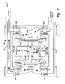
- FIG. 2 is a front cross-section view of the positive displacement pneumatic motor showing fluid flow.
- FIG. 3A is a front cross-section view of a muffler showing sound absorbing material and a diffuser.
- FIG. 3B is a side cross-section view of the muffler showing an inlet along section line 3 B- 3 B in FIG. 3A .
- FIG. 4 is a front cross-section view of an alternate embodiment muffler showing a deflection cone, sound absorbing material, and support plates.
- FIG. 5 is a perspective view of an alternate embodiment muffler showing an alternate embodiment diffuser.
- FIG. 6 is a side cross-section view of an alternate embodiment muffler showing sound absorbing material and support plates.
- FIG. 1 a front view of positive displacement pneumatic motor 10 is shown. Shown in FIG. 1 are motor 10 , muffler 12 , -fluid source 14 , fluid inlet 16 , fluid destination 18 , fluid outlet 20 , compressed gas source 22 , and pneumatic inlet 24 .
- Motor 10 is connected to fluid source 14 at fluid inlet 16 and to fluid destination 18 at fluid outlet 20 .
- Motor 10 is also connected to compressed gas source 22 at pneumatic inlet 24 .
- Attached to the exterior of motor 10 is muffler 12 .
- motor 10 is a double diaphragm pump. Thereby, motor 10 uses compressed gas from compressed gas source 22 to pump fluid from fluid source 14 to fluid destination 18 . As part of the working cycle of motor 10 , used compressed gas is exhausted to the atmosphere through muffler 12 .
- motor 10 can be a different type of pneumatic device, such as, a pneumatic cylinder.
- motor 10 is not a pump, so fluid source 14 , fluid inlet 16 , fluid destination, and fluid outlet 20 are not required.
- FIG. 2 a front cross-section view of positive displacement pneumatic motor 10 , including internal fluid flow, is shown. Shown in FIG. 2 are motor 10 , muffler 12 , fluid inlet 16 , fluid outlet 20 , pneumatic inlet 24 , motor body 30 , inlet manifold 32 , outlet manifold 34 , fluid chambers 36 A- 36 B, check valves 38 A- 38 D, diaphragms 40 A- 40 B, gas manifold 42 , gas chambers 44 A- 44 B, gas valve 46 , piston 48 , and pneumatic outlet 50 .
- Motor 10 has motor body 30 which includes fluid inlet 16 , fluid outlet 20 , and pneumatic inlet 24 .
- Fluidly connected to fluid inlet 16 is inlet manifold 32 and fluidly connected to fluid outlet 20 is outlet manifold 34 .
- Extending between inlet manifold 32 and outlet manifold 34 are fluid chambers 36 A- 36 B.
- Fluid chamber 36 A is bounded by motor body 30 , check valves 38 A- 38 B, and diaphragm 40 A.
- Fluid chamber 36 B is bounded by motor body 30 , check valves 38 C- 38 D, and diaphragm 40 B.
- gas valve 46 Slidably positioned in gas manifold 42 near gas chambers 44 A- 44 B is gas valve 46 .
- Gas valve 46 covers pneumatic outlet 50 .
- Fluidly connected to pneumatic outlet 50 and attached to motor body 30 is muffler 12 .
- valve actuator moves gas valve 46 side-to-side.
- gas valve 46 is positioned between gas manifold 42 and gas chamber 44 A. This causes compressed gas from gas manifold 42 to flow into gas chamber 44 B. The compressed gas exerts force on diaphragm 40 B, expanding gas chamber 44 B and causing diaphragm 40 B and piston 48 to move toward fluid chamber 36 B. This movement reduces the volume of fluid chamber 36 B, forcing fluid contained therein through check valve 38 D into outlet manifold 34 (because check valve 38 C prevents backflow into inlet manifold 32 ).
- motor 10 allows for compressed gas from compressed gas source 22 (shown in FIG. 1 ) to be used to pump fluid from fluid source 14 to fluid destination 18 (both shown in FIG. 1 ).
- compressed gas is used, it is exhausted to the atmosphere through muffler 12 .
- FIG. 3A a front cross-section view of muffler 12 is shown, including sound absorbing material 68 and diffuser 64 .
- FIG. 3B a side cross-section view of muffler 12 is shown, including inlet 62 . Shown in FIGS. 3A-3B are muffler 12 , muffler case 60 , muffler inlet 62 , diffuser 64 , pathway 66 , sound absorbing material 68 , septum 70 , ducts 72 , diffuser ramps 74 , diffuser supports 76 , and muffler axis 78 . The discussion of FIGS. 3A-3B will occur simultaneously.
- Muffler 12 includes muffler case 60 , to which muffler inlet 62 is attached. Diffuser 64 is also attached to muffler case 60 . Extending through the interior of muffler case 60 , between muffler inlet 62 and diffuser 64 , is pathway 66 . Positioned in pathway 66 is sound absorbing material 68 .
- sound absorbing material 68 is comprised of a number of die-cut layers of felt material that are stacked axially inside of muffler case 60 (along muffler axis 78 ). Sound absorbing material 68 has two ducts 72 , which are separated by septum 70 . Ducts 72 are substantially parallel to muffler axis 78 and are substantially orthogonal to muffler inlet 62 .
- diffuser 64 is comprised of two diffuser ramps 74 and two diffuser supports 76 .
- Diffuser ramps 74 begin near septum 70 and extend away from muffler case 60 .
- Diffuser ramps 74 also curve radially outward away from muffler axis 78 and extend substantially to the projections of the outer edges of ducts 72 , respectively.
- Diffuser supports 76 are positioned alongside diffuser ramps 74 and each diffuser support 74 is attached to both muffler case 60 and diffuser ramps 74 .
- Diffuser supports 74 provide structural support to diffuser ramps 74 .
- the gas As the gas is exhausted from muffler 12 , it decompresses until it reaches atmospheric pressure. The gas is also allowed to expand radially outward in substantially all directions. The only restriction on being a complete three-hundred-sixty degree expansion is diffuser supports 76 . This broad distribution of the exhausting gas is less damaging, dangerous, and annoying to the surrounding environment and bystanders.
- the components and configuration of muffler 12 as shown in FIGS. 3A-3B allow for the reduction of noise caused by the compressed gas being exhausted. This occurs due to the ninety degree turn in pathway 66 after muffler inlet 62 , sound absorbing material 68 and ducts 72 , and diffuser ramps 74 .
- the ninety degree turn in pathway 66 slows the gas, which causes the gas to spend more time in muffler 12 prior to exiting. This exposes the gas to sound absorbing material 68 for a longer period of time, allowing sound absorbing material 68 to convert more sonic energy to heat energy.
- ducts 72 having a plurality of ducts 72 increases the surface area of sound absorbing material 68 that the exiting gas is exposed to.
- diffuser ramps 74 not only do they disperse the exiting gas but they also block a direct line-of-sight flow path from muffler inlet 62 to the atmosphere.
- any ice that is formed in motor 10 can be expelled therefrom. This is because muffler inlet 62 , pathway 66 , ducts 72 , and diffuser 64 are sufficiently large, and sound absorbing material 68 does not obstruct the flow of gas through muffler 12 . Moreover, exiting gas flows alongside of sound absorbing material 68 and is not forced to travel through the bulk of sound absorbing material 68 . Therefore, ice can be propelled by exiting gas through muffler 12 without getting captured or trapped inside muffler 12 .
- the gas is exhausted from muffler 12 over a broad area, as opposed to a narrow jet that can be harmful by propelling ice fragments, dispersing resting dust into the atmosphere, removing paint from surfaces, distracting users, among other things.
- the ninety degree bend in pathway 66 prevents muffler 12 from projecting straight away from motor 10 (shown in FIG. 1 ). Instead, muffler 12 has a low profile that lies alongside of motor body 30 (shown in FIG. 2 ).
- muffler 12 can have more than two ducts 72 . In such an embodiment, there is also more than one septum 70 .
- muffler 12 can have one duct 72 , and such an embodiment does not require septum 70 .
- diffuser ramps 74 can extend past the projections of the outer edges of ducts 72 , respectively.
- sound absorbing material 68 can be comprised of a variety of sound absorbing materials, such as sintered metal or open cell foam.
- FIG. 4 a front cross-section view of an alternate embodiment muffler 12 is shown, including deflection cone 90 , sound absorbing material 68 , and support plates 92 . Shown in FIG. 4 are muffler 12 , muffler case 60 , muffler inlet 62 , pathway 66 , sound absorbing material 68 A- 68 B, ducts 72 A- 72 B, muffler axis 78 , deflection cone 90 , and support plates 92 .
- support plates 92 are attached to the inside of muffler case 60 and are axially positioned between sections of sound absorbing material 68 A- 68 B.
- Support plates 92 can be comprised of a rigid material, such as aluminum, or of a flexible material, such as rubber.
- support plates 92 include the same hole pattern as ducts 72 A to allow for gas flow through support plates 92 .
- support plates 92 structurally support sound absorbing material 68 and can assist with decreasing the noise level of muffler 12 by noise reflection.
- diffuser 64 is scoop-shaped and is rotatably attached to muffler case 60 . More specifically, diffuser 64 includes a groove around the circular ring at top of diffuser 64 . Diffuser 64 is captured when the two halves of muffler case 60 are joined, with the bottom of muffler case 60 fitting in the groove. Diffuser 64 has an L-shaped extension below the circular ring made up of a support or strut that extends from the ring and a generally circular deflection plate or ramp spaced from and aligned with the opening defined by the circular ring.
- the gas flow from both ducts 72 is directed in the same general direction through an opening in diffuser 64 . More specifically, gas flow is prohibited by the support or strut portion diffuser 64 through a substantial angle.
- the orientation of diffuser 64 (and therefore, the direction of exhaust flow) is selectable by the operator by rotating diffuser 64 about muffler axis 78 .
- a detent (not shown) allows for positioning of diffuser 64 every forty-five degrees.
- alternate embodiment muffler 12 as shown in FIG. 5 allow the operator of motor 10 (shown in FIG. 1 ) to orient the exhaust gas flow, preventing it from flowing in a disadvantageous direction (for example, toward the operator). This orientation occurs without resulting in the formation of an exhaust gas jet.
- muffler 12 can have a detent that allows for positioning in even increments other than forty-five degrees (such as every thirty degrees).
- muffler 12 can use friction in the joint between muffler case 60 and diffuser 64 in order to hold diffuser 64 in a particular orientation.
- FIG. 6 a side cross-section view of an alternate embodiment muffler 12 is shown, including sound absorbing material 68 and support plates 92 . Shown in FIG. 6 are muffler 12 , muffler case 60 , pathway 66 , sound absorbing material 68 , and support plates 92 .
- support plates 92 have axial holes 94 that are covered on one side by sound absorbing material 68 . This is because sound absorbing material is positioned alternately between support plates 92 . This leaves open spaces in pathway 66 where there is no sound absorbing material between pathway 66 and muffler case 60 .
- the components and configuration of alternate embodiment muffler 12 as shown in FIG. 6 can allow for better noise reduction capability, depending on the operational parameters. This can occur due to support plates 92 causing noise reflection and destructive interference.
- frost accumulation is less in the open spaces between support plates 92 than it is in ducts 72 . Because of axial holes 94 , the gas can still reach sound absorbing material 68 through support plates 92 .
- the present invention provides numerous benefits and advantages.
- the noise level of gas being exhausted from motor 10 is reduced to an acceptable level.
- ice that is formed by motor 10 can exit motor 10 without undue restriction from muffler 12 .
- motor 10 can be more compact because muffler 12 is alongside motor body 30 .
Landscapes
- Engineering & Computer Science (AREA)
- Mechanical Engineering (AREA)
- General Engineering & Computer Science (AREA)
- Chemical & Material Sciences (AREA)
- Combustion & Propulsion (AREA)
- Analytical Chemistry (AREA)
- Physics & Mathematics (AREA)
- Fluid Mechanics (AREA)
- Compressor (AREA)
- Exhaust Silencers (AREA)
- Jet Pumps And Other Pumps (AREA)
Priority Applications (1)
| Application Number | Priority Date | Filing Date | Title |
|---|---|---|---|
| US13/698,397 US9464630B2 (en) | 2010-05-18 | 2011-05-18 | Low ice pneumatic motor exhaust muffler |
Applications Claiming Priority (3)
| Application Number | Priority Date | Filing Date | Title |
|---|---|---|---|
| US34565510P | 2010-05-18 | 2010-05-18 | |
| PCT/US2011/000881 WO2011146118A2 (en) | 2010-05-18 | 2011-05-18 | Low ice pneumatic motor exhaust muffler |
| US13/698,397 US9464630B2 (en) | 2010-05-18 | 2011-05-18 | Low ice pneumatic motor exhaust muffler |
Publications (2)
| Publication Number | Publication Date |
|---|---|
| US20130058802A1 US20130058802A1 (en) | 2013-03-07 |
| US9464630B2 true US9464630B2 (en) | 2016-10-11 |
Family
ID=44992250
Family Applications (1)
| Application Number | Title | Priority Date | Filing Date |
|---|---|---|---|
| US13/698,397 Expired - Fee Related US9464630B2 (en) | 2010-05-18 | 2011-05-18 | Low ice pneumatic motor exhaust muffler |
Country Status (8)
| Country | Link |
|---|---|
| US (1) | US9464630B2 (de) |
| EP (1) | EP2572082B1 (de) |
| KR (1) | KR101774076B1 (de) |
| CN (2) | CN102892983A (de) |
| AU (1) | AU2011256835B2 (de) |
| PL (1) | PL2572082T3 (de) |
| TR (1) | TR201908260T4 (de) |
| WO (1) | WO2011146118A2 (de) |
Cited By (1)
| Publication number | Priority date | Publication date | Assignee | Title |
|---|---|---|---|---|
| US11808490B2 (en) | 2017-10-11 | 2023-11-07 | Carrier Corporation | Muffler with metallic meshed rings |
Families Citing this family (7)
| Publication number | Priority date | Publication date | Assignee | Title |
|---|---|---|---|---|
| NZ630340A (en) * | 2013-05-14 | 2016-04-29 | Joe Santa & Ass Pty Ltd | A valve for a diaphragm pump |
| AU2015370583B2 (en) | 2014-12-22 | 2020-08-20 | Smith & Nephew Plc | Negative pressure wound therapy apparatus and methods |
| US9677557B2 (en) * | 2015-01-20 | 2017-06-13 | Hao Hsu | Sleeping system |
| JP7176931B2 (ja) * | 2018-11-05 | 2022-11-22 | 大陽日酸株式会社 | Psa装置用消音器の先端部構造及びpsa装置用消音器 |
| CN110017266B (zh) * | 2019-04-04 | 2024-03-22 | 瑞安市乐登汽车部件有限公司 | 一种气动消声器 |
| CN110410299B (zh) * | 2019-09-02 | 2024-03-08 | 深圳市博威克斯科技有限公司 | 一种具有多重压缩效果的隔膜泵 |
| CN110486351B (zh) * | 2019-09-11 | 2022-04-05 | 襄阳元创汽车零部件实业有限公司 | 一种500t送料机排气消音器及其操作方法 |
Citations (33)
| Publication number | Priority date | Publication date | Assignee | Title |
|---|---|---|---|---|
| US1844104A (en) * | 1929-05-08 | 1932-02-09 | Burgess Lab Inc C F | Exhaust muffler |
| US2205899A (en) * | 1939-05-01 | 1940-06-25 | Burgess Battery Co | Silencing device for pulsating gases |
| US2773553A (en) | 1953-02-13 | 1956-12-11 | Maschf Augsburg Nuernberg Ag | Muffler |
| US3142354A (en) * | 1960-08-09 | 1964-07-28 | Gutehoffnungshuette Sterkrade | Sound absorption device and method of manufacture |
| US3842932A (en) * | 1972-11-01 | 1974-10-22 | S Gibel | Sound-trap muffler |
| US4109749A (en) * | 1976-11-09 | 1978-08-29 | Minnesota Mining And Manufacturing Company | Muffler |
| GB2070682A (en) | 1980-02-09 | 1981-09-09 | Engineering Components Ltd | Silencer for the inlet to an air cleaner |
| US4523662A (en) | 1981-11-05 | 1985-06-18 | Mitsubishi Denki Kabushiki Kaisha | Muffler for exhaust gas from an internal combustion engine |
| EP0727580A1 (de) | 1995-02-14 | 1996-08-21 | Itt Manufacturing Enterprises, Inc. | Druckluftbetätigte Wechselventilanordnung zum Antrieb einer Hubkolbenpumpe |
| US5559310A (en) | 1995-04-26 | 1996-09-24 | Ingersoll-Rand Company | Muffler for air operated reciprocating pumps |
| US5869793A (en) * | 1996-12-11 | 1999-02-09 | Supertrapp Industries, Inc. | Oval shaped spark arresting muffler for engines |
| US5893707A (en) | 1994-03-03 | 1999-04-13 | Simmons; John M. | Pneumatically shifted reciprocating pump |
| JP2001271626A (ja) | 2000-03-24 | 2001-10-05 | Mitsubishi Heavy Ind Ltd | 吐出流体の騒音防止装置 |
| US6332511B1 (en) * | 1999-12-07 | 2001-12-25 | Burgess-Manning, Inc. | Silencer assembly having single strand fiberglass acoustic pack material |
| KR20030008064A (ko) | 2001-07-16 | 2003-01-24 | 주식회사 카튜너 | 저소음 튜닝머플러 |
| US20030070870A1 (en) * | 2001-10-15 | 2003-04-17 | Reynolds Steven M. | Sound attenuator for pneumatic exhaust |
| US20040065504A1 (en) * | 2002-10-02 | 2004-04-08 | Daniels Mark A. | Absorptive/reactive muffler for variable speed compressors |
| US20040126247A1 (en) * | 2002-10-16 | 2004-07-01 | Dietmar Broser | Muffler for air compressor |
| US20040163887A1 (en) * | 2003-02-25 | 2004-08-26 | Ziehl John C. | Exhaust silencer system |
| US6880670B2 (en) * | 2002-10-29 | 2005-04-19 | Beda Charles Dondi | Muffler for suction system exhaust air used with an automatic cutting machine |
| US20050103566A1 (en) * | 1998-01-13 | 2005-05-19 | Exhaust Technologies, Inc. | Muffler for pneumatic hand tool |
| US6983820B2 (en) * | 2001-09-07 | 2006-01-10 | Avon Polymer Products Limited | Noise and vibration suppressors |
| US20080023265A1 (en) * | 2004-05-28 | 2008-01-31 | Silentor Holding A/S | Combination Silencer |
| US20080083582A1 (en) * | 2006-10-06 | 2008-04-10 | Towne Lloyd I | Exhaust system |
| CN201078255Y (zh) | 2007-07-20 | 2008-06-25 | 梁正贤 | 消音套筒 |
| US20080314679A1 (en) * | 2005-08-05 | 2008-12-25 | Rowe Grant M | Variable Sound Muffler System |
| US20090060759A1 (en) * | 2004-10-20 | 2009-03-05 | Sishtla Vishnu M | Compressor sound suppression |
| US20090090530A1 (en) * | 2007-07-13 | 2009-04-09 | Longyear Tm, Inc. | Noise abatement device for a pneumatic tool |
| US20090107760A1 (en) * | 2007-10-24 | 2009-04-30 | Sammut Paul H | Exhaust system and muffler with reversible end-caps |
| CN201236736Y (zh) | 2008-08-06 | 2009-05-13 | 哈尔滨东安发动机(集团)有限公司 | 排气消声装置 |
| JP2009519394A (ja) | 2005-12-01 | 2009-05-14 | テネコ オートモティブ オペレーティング カンパニー インコーポレイテッド | 吸音材を備える消音装置 |
| KR100939702B1 (ko) | 2009-11-06 | 2010-02-01 | 한국방진방음 주식회사 | 고감음 공업용 소음기 |
| CN101705956A (zh) | 2009-03-26 | 2010-05-12 | 重庆长江涂装机械厂 | 一种气动马达的除冰方法及其装置 |
Family Cites Families (5)
| Publication number | Priority date | Publication date | Assignee | Title |
|---|---|---|---|---|
| FR2144968A5 (de) * | 1971-07-05 | 1973-02-16 | Wilman Sigismond | |
| CA1120406A (en) * | 1979-02-13 | 1982-03-23 | Stanley L. Baldwin | Mufflers for percussive pneumatic machines |
| JPH08177461A (ja) * | 1994-07-15 | 1996-07-09 | Owens Corning Fiberglass Corp | エンジン排気マフラー用の予備成形された消音材料 |
| KR200187360Y1 (ko) * | 1996-12-31 | 2000-07-01 | 정몽규 | 흡음재를 내장한 소음기 |
| FR2790788B1 (fr) * | 1999-03-12 | 2001-04-27 | Penel Rech Et Dev | Silencieux-detendeur pour moteurs a explosions |
-
2011
- 2011-05-18 CN CN2011800244496A patent/CN102892983A/zh active Pending
- 2011-05-18 CN CN201510789620.2A patent/CN105332894B/zh not_active Expired - Fee Related
- 2011-05-18 KR KR1020127033121A patent/KR101774076B1/ko not_active Expired - Fee Related
- 2011-05-18 TR TR2019/08260T patent/TR201908260T4/tr unknown
- 2011-05-18 EP EP11783862.3A patent/EP2572082B1/de not_active Not-in-force
- 2011-05-18 US US13/698,397 patent/US9464630B2/en not_active Expired - Fee Related
- 2011-05-18 AU AU2011256835A patent/AU2011256835B2/en not_active Ceased
- 2011-05-18 PL PL11783862T patent/PL2572082T3/pl unknown
- 2011-05-18 WO PCT/US2011/000881 patent/WO2011146118A2/en not_active Ceased
Patent Citations (34)
| Publication number | Priority date | Publication date | Assignee | Title |
|---|---|---|---|---|
| US1844104A (en) * | 1929-05-08 | 1932-02-09 | Burgess Lab Inc C F | Exhaust muffler |
| US2205899A (en) * | 1939-05-01 | 1940-06-25 | Burgess Battery Co | Silencing device for pulsating gases |
| US2773553A (en) | 1953-02-13 | 1956-12-11 | Maschf Augsburg Nuernberg Ag | Muffler |
| US3142354A (en) * | 1960-08-09 | 1964-07-28 | Gutehoffnungshuette Sterkrade | Sound absorption device and method of manufacture |
| US3842932A (en) * | 1972-11-01 | 1974-10-22 | S Gibel | Sound-trap muffler |
| US4109749A (en) * | 1976-11-09 | 1978-08-29 | Minnesota Mining And Manufacturing Company | Muffler |
| GB2070682A (en) | 1980-02-09 | 1981-09-09 | Engineering Components Ltd | Silencer for the inlet to an air cleaner |
| US4523662A (en) | 1981-11-05 | 1985-06-18 | Mitsubishi Denki Kabushiki Kaisha | Muffler for exhaust gas from an internal combustion engine |
| US5893707A (en) | 1994-03-03 | 1999-04-13 | Simmons; John M. | Pneumatically shifted reciprocating pump |
| US5567118A (en) * | 1995-02-14 | 1996-10-22 | Itt Fluid Technology Corporation | Non-lubricated, air-actuated, pump-operating, shuttle valve arrangement, in a reciprocating pump |
| EP0727580A1 (de) | 1995-02-14 | 1996-08-21 | Itt Manufacturing Enterprises, Inc. | Druckluftbetätigte Wechselventilanordnung zum Antrieb einer Hubkolbenpumpe |
| US5559310A (en) | 1995-04-26 | 1996-09-24 | Ingersoll-Rand Company | Muffler for air operated reciprocating pumps |
| US5869793A (en) * | 1996-12-11 | 1999-02-09 | Supertrapp Industries, Inc. | Oval shaped spark arresting muffler for engines |
| US20050103566A1 (en) * | 1998-01-13 | 2005-05-19 | Exhaust Technologies, Inc. | Muffler for pneumatic hand tool |
| US6332511B1 (en) * | 1999-12-07 | 2001-12-25 | Burgess-Manning, Inc. | Silencer assembly having single strand fiberglass acoustic pack material |
| JP2001271626A (ja) | 2000-03-24 | 2001-10-05 | Mitsubishi Heavy Ind Ltd | 吐出流体の騒音防止装置 |
| KR20030008064A (ko) | 2001-07-16 | 2003-01-24 | 주식회사 카튜너 | 저소음 튜닝머플러 |
| US6983820B2 (en) * | 2001-09-07 | 2006-01-10 | Avon Polymer Products Limited | Noise and vibration suppressors |
| US20030070870A1 (en) * | 2001-10-15 | 2003-04-17 | Reynolds Steven M. | Sound attenuator for pneumatic exhaust |
| US20040065504A1 (en) * | 2002-10-02 | 2004-04-08 | Daniels Mark A. | Absorptive/reactive muffler for variable speed compressors |
| US20040126247A1 (en) * | 2002-10-16 | 2004-07-01 | Dietmar Broser | Muffler for air compressor |
| US6880670B2 (en) * | 2002-10-29 | 2005-04-19 | Beda Charles Dondi | Muffler for suction system exhaust air used with an automatic cutting machine |
| US20040163887A1 (en) * | 2003-02-25 | 2004-08-26 | Ziehl John C. | Exhaust silencer system |
| US20080023265A1 (en) * | 2004-05-28 | 2008-01-31 | Silentor Holding A/S | Combination Silencer |
| US20090060759A1 (en) * | 2004-10-20 | 2009-03-05 | Sishtla Vishnu M | Compressor sound suppression |
| US20080314679A1 (en) * | 2005-08-05 | 2008-12-25 | Rowe Grant M | Variable Sound Muffler System |
| JP2009519394A (ja) | 2005-12-01 | 2009-05-14 | テネコ オートモティブ オペレーティング カンパニー インコーポレイテッド | 吸音材を備える消音装置 |
| US20080083582A1 (en) * | 2006-10-06 | 2008-04-10 | Towne Lloyd I | Exhaust system |
| US20090090530A1 (en) * | 2007-07-13 | 2009-04-09 | Longyear Tm, Inc. | Noise abatement device for a pneumatic tool |
| CN201078255Y (zh) | 2007-07-20 | 2008-06-25 | 梁正贤 | 消音套筒 |
| US20090107760A1 (en) * | 2007-10-24 | 2009-04-30 | Sammut Paul H | Exhaust system and muffler with reversible end-caps |
| CN201236736Y (zh) | 2008-08-06 | 2009-05-13 | 哈尔滨东安发动机(集团)有限公司 | 排气消声装置 |
| CN101705956A (zh) | 2009-03-26 | 2010-05-12 | 重庆长江涂装机械厂 | 一种气动马达的除冰方法及其装置 |
| KR100939702B1 (ko) | 2009-11-06 | 2010-02-01 | 한국방진방음 주식회사 | 고감음 공업용 소음기 |
Non-Patent Citations (5)
| Title |
|---|
| English translation of second Chinese Office Action dated May 5, 2015, for corresponding Chinese Application No. 201180024449.6. |
| Examination Report dated Dec. 3, 2014, for corresponding Australian Patent Application No. 2011256835. |
| Extended European Search Report for EP Application No. 11783862.3, dated Jun. 13, 2016, 7 pages. |
| The International Search Report and Written Opinion in counterpart International Application No. PCT/US2011/000881 filed May 18, 2011. |
| Translation of first Office Action received in corresponding Chinese application No. 201180024449.6, issued Aug. 14, 2014. |
Cited By (2)
| Publication number | Priority date | Publication date | Assignee | Title |
|---|---|---|---|---|
| US11808490B2 (en) | 2017-10-11 | 2023-11-07 | Carrier Corporation | Muffler with metallic meshed rings |
| US12050032B2 (en) | 2017-10-11 | 2024-07-30 | Carrier Corporation | Muffler with metallic meshed rings |
Also Published As
| Publication number | Publication date |
|---|---|
| CN105332894A (zh) | 2016-02-17 |
| EP2572082B1 (de) | 2019-05-01 |
| WO2011146118A2 (en) | 2011-11-24 |
| WO2011146118A3 (en) | 2012-02-23 |
| EP2572082A2 (de) | 2013-03-27 |
| EP2572082A4 (de) | 2016-07-13 |
| PL2572082T3 (pl) | 2019-08-30 |
| CN102892983A (zh) | 2013-01-23 |
| KR101774076B1 (ko) | 2017-09-01 |
| US20130058802A1 (en) | 2013-03-07 |
| AU2011256835B2 (en) | 2015-07-16 |
| CN105332894B (zh) | 2018-01-12 |
| KR20130069667A (ko) | 2013-06-26 |
| TR201908260T4 (tr) | 2019-06-21 |
| AU2011256835A1 (en) | 2012-10-11 |
Similar Documents
| Publication | Publication Date | Title |
|---|---|---|
| US9464630B2 (en) | Low ice pneumatic motor exhaust muffler | |
| US9915362B2 (en) | Fluidic diode check valve | |
| CN116357550A (zh) | 空气压缩机系统 | |
| EP1872069A1 (de) | Vorrichtung zur verwendung als wärmepumpe | |
| KR101790855B1 (ko) | 유체실린더 | |
| FI66558C (fi) | Ljuddaempare foer luftdrivna slagverktyg | |
| EP2891801A2 (de) | Verdichter- und Ventilanordnung davon zur Verringerung von Pulsationen und/oder Geräuschen | |
| CN104903038A (zh) | 流体驱动马达的可变速度控制 | |
| US20180347553A1 (en) | Double-acting pneumatic pump | |
| US11067084B2 (en) | Pulsation mufflers for compressors | |
| WO2007109788A3 (en) | Fluid propulsion device | |
| US20200109713A1 (en) | Integrated rotary positive-displacement machinery | |
| CA2955709C (en) | Improved rotary vane vacuum pump | |
| KR20090011802U (ko) | 유동 균일화를 위한 디퓨져 구조를 가지는 소음기 | |
| KR102640985B1 (ko) | 소음감소를 위한 에어콤프레셔 설치용 소음방지장치 | |
| US9003949B2 (en) | Automatic pneumatic valve reset system | |
| CN203515996U (zh) | 微型泵及其气阀结构 | |
| GB2568477A (en) | Double-acting pneumatic pump | |
| CN108050065B (zh) | 压缩机和具有其的空调器 | |
| CN106489025B (zh) | 压缩机 | |
| KR20180108993A (ko) | 컴프레서 | |
| CN118375769A (zh) | 一种气动控制系统 | |
| KR20130141297A (ko) | 압축기 어셈블리 | |
| JP2002130211A (ja) | リニア・ガイド |
Legal Events
| Date | Code | Title | Description |
|---|---|---|---|
| AS | Assignment |
Owner name: GRACO MINNESOTA INC., MINNESOTA Free format text: ASSIGNMENT OF ASSIGNORS INTEREST;ASSIGNORS:ROMAN, TIMOTHY S.;COLLINS, ADAM K.;REEL/FRAME:035214/0877 Effective date: 20121120 |
|
| STCF | Information on status: patent grant |
Free format text: PATENTED CASE |
|
| MAFP | Maintenance fee payment |
Free format text: PAYMENT OF MAINTENANCE FEE, 4TH YEAR, LARGE ENTITY (ORIGINAL EVENT CODE: M1551); ENTITY STATUS OF PATENT OWNER: LARGE ENTITY Year of fee payment: 4 |
|
| FEPP | Fee payment procedure |
Free format text: MAINTENANCE FEE REMINDER MAILED (ORIGINAL EVENT CODE: REM.); ENTITY STATUS OF PATENT OWNER: LARGE ENTITY |
|
| LAPS | Lapse for failure to pay maintenance fees |
Free format text: PATENT EXPIRED FOR FAILURE TO PAY MAINTENANCE FEES (ORIGINAL EVENT CODE: EXP.); ENTITY STATUS OF PATENT OWNER: LARGE ENTITY |
|
| STCH | Information on status: patent discontinuation |
Free format text: PATENT EXPIRED DUE TO NONPAYMENT OF MAINTENANCE FEES UNDER 37 CFR 1.362 |
|
| FP | Lapsed due to failure to pay maintenance fee |
Effective date: 20241011 |