US9446894B2 - Valve for pressurized container - Google Patents
Valve for pressurized container Download PDFInfo
- Publication number
- US9446894B2 US9446894B2 US14/797,521 US201514797521A US9446894B2 US 9446894 B2 US9446894 B2 US 9446894B2 US 201514797521 A US201514797521 A US 201514797521A US 9446894 B2 US9446894 B2 US 9446894B2
- Authority
- US
- United States
- Prior art keywords
- valve
- mounting cup
- seal
- bottom wall
- stem
- Prior art date
- Legal status (The legal status is an assumption and is not a legal conclusion. Google has not performed a legal analysis and makes no representation as to the accuracy of the status listed.)
- Active
Links
- 239000011324 bead Substances 0.000 claims abstract description 46
- 230000007704 transition Effects 0.000 claims abstract description 40
- 230000009969 flowable effect Effects 0.000 claims abstract description 15
- 230000002093 peripheral effect Effects 0.000 claims description 13
- 230000001154 acute effect Effects 0.000 claims description 5
- 238000007789 sealing Methods 0.000 claims description 4
- 238000010276 construction Methods 0.000 claims description 2
- 229920002725 thermoplastic elastomer Polymers 0.000 claims description 2
- 239000004636 vulcanized rubber Substances 0.000 claims description 2
- 239000000443 aerosol Substances 0.000 description 7
- 239000002184 metal Substances 0.000 description 6
- 229910052751 metal Inorganic materials 0.000 description 6
- 101710187795 60S ribosomal protein L15 Proteins 0.000 description 5
- 230000008901 benefit Effects 0.000 description 5
- 238000002788 crimping Methods 0.000 description 5
- 229910000831 Steel Inorganic materials 0.000 description 4
- 238000013461 design Methods 0.000 description 4
- 239000010959 steel Substances 0.000 description 4
- 102100031854 60S ribosomal protein L14 Human genes 0.000 description 3
- 101000704267 Homo sapiens 60S ribosomal protein L14 Proteins 0.000 description 3
- 101100141719 Human cytomegalovirus (strain Merlin) RL13 gene Proteins 0.000 description 3
- 101100249083 Human cytomegalovirus (strain Merlin) RL12 gene Proteins 0.000 description 2
- 229920005830 Polyurethane Foam Polymers 0.000 description 2
- 230000004323 axial length Effects 0.000 description 2
- 230000008859 change Effects 0.000 description 2
- 238000000034 method Methods 0.000 description 2
- 238000004806 packaging method and process Methods 0.000 description 2
- 239000011496 polyurethane foam Substances 0.000 description 2
- 101100195396 Human cytomegalovirus (strain Merlin) RL11 gene Proteins 0.000 description 1
- 239000004433 Thermoplastic polyurethane Substances 0.000 description 1
- 229910052782 aluminium Inorganic materials 0.000 description 1
- XAGFODPZIPBFFR-UHFFFAOYSA-N aluminium Chemical compound [Al] XAGFODPZIPBFFR-UHFFFAOYSA-N 0.000 description 1
- 238000013459 approach Methods 0.000 description 1
- 238000000748 compression moulding Methods 0.000 description 1
- 229920001971 elastomer Polymers 0.000 description 1
- 235000013305 food Nutrition 0.000 description 1
- 230000002401 inhibitory effect Effects 0.000 description 1
- 238000001746 injection moulding Methods 0.000 description 1
- 230000000670 limiting effect Effects 0.000 description 1
- 239000007769 metal material Substances 0.000 description 1
- 238000012986 modification Methods 0.000 description 1
- 230000004048 modification Effects 0.000 description 1
- 230000036961 partial effect Effects 0.000 description 1
- 229920001084 poly(chloroprene) Polymers 0.000 description 1
- 230000008569 process Effects 0.000 description 1
- 230000002829 reductive effect Effects 0.000 description 1
- 239000012858 resilient material Substances 0.000 description 1
- 238000007493 shaping process Methods 0.000 description 1
- 238000010008 shearing Methods 0.000 description 1
- 229910001220 stainless steel Inorganic materials 0.000 description 1
- 239000010935 stainless steel Substances 0.000 description 1
- 239000000126 substance Substances 0.000 description 1
- 229920002803 thermoplastic polyurethane Polymers 0.000 description 1
- 229920001187 thermosetting polymer Polymers 0.000 description 1
- 239000005028 tinplate Substances 0.000 description 1
- 238000001721 transfer moulding Methods 0.000 description 1
Images


Classifications
-
- B—PERFORMING OPERATIONS; TRANSPORTING
- B65—CONVEYING; PACKING; STORING; HANDLING THIN OR FILAMENTARY MATERIAL
- B65D—CONTAINERS FOR STORAGE OR TRANSPORT OF ARTICLES OR MATERIALS, e.g. BAGS, BARRELS, BOTTLES, BOXES, CANS, CARTONS, CRATES, DRUMS, JARS, TANKS, HOPPERS, FORWARDING CONTAINERS; ACCESSORIES, CLOSURES, OR FITTINGS THEREFOR; PACKAGING ELEMENTS; PACKAGES
- B65D83/00—Containers or packages with special means for dispensing contents
- B65D83/14—Containers or packages with special means for dispensing contents for delivery of liquid or semi-liquid contents by internal gaseous pressure, i.e. aerosol containers comprising propellant for a product delivered by a propellant
- B65D83/44—Valves specially adapted therefor; Regulating devices
- B65D83/48—Lift valves, e.g. operated by push action
-
- B—PERFORMING OPERATIONS; TRANSPORTING
- B65—CONVEYING; PACKING; STORING; HANDLING THIN OR FILAMENTARY MATERIAL
- B65D—CONTAINERS FOR STORAGE OR TRANSPORT OF ARTICLES OR MATERIALS, e.g. BAGS, BARRELS, BOTTLES, BOXES, CANS, CARTONS, CRATES, DRUMS, JARS, TANKS, HOPPERS, FORWARDING CONTAINERS; ACCESSORIES, CLOSURES, OR FITTINGS THEREFOR; PACKAGING ELEMENTS; PACKAGES
- B65D83/00—Containers or packages with special means for dispensing contents
- B65D83/14—Containers or packages with special means for dispensing contents for delivery of liquid or semi-liquid contents by internal gaseous pressure, i.e. aerosol containers comprising propellant for a product delivered by a propellant
- B65D83/38—Details of the container body
-
- B—PERFORMING OPERATIONS; TRANSPORTING
- B65—CONVEYING; PACKING; STORING; HANDLING THIN OR FILAMENTARY MATERIAL
- B65D—CONTAINERS FOR STORAGE OR TRANSPORT OF ARTICLES OR MATERIALS, e.g. BAGS, BARRELS, BOTTLES, BOXES, CANS, CARTONS, CRATES, DRUMS, JARS, TANKS, HOPPERS, FORWARDING CONTAINERS; ACCESSORIES, CLOSURES, OR FITTINGS THEREFOR; PACKAGING ELEMENTS; PACKAGES
- B65D83/00—Containers or packages with special means for dispensing contents
- B65D83/14—Containers or packages with special means for dispensing contents for delivery of liquid or semi-liquid contents by internal gaseous pressure, i.e. aerosol containers comprising propellant for a product delivered by a propellant
- B65D83/44—Valves specially adapted therefor; Regulating devices
- B65D83/46—Tilt valves
-
- F—MECHANICAL ENGINEERING; LIGHTING; HEATING; WEAPONS; BLASTING
- F16—ENGINEERING ELEMENTS AND UNITS; GENERAL MEASURES FOR PRODUCING AND MAINTAINING EFFECTIVE FUNCTIONING OF MACHINES OR INSTALLATIONS; THERMAL INSULATION IN GENERAL
- F16K—VALVES; TAPS; COCKS; ACTUATING-FLOATS; DEVICES FOR VENTING OR AERATING
- F16K1/00—Lift valves or globe valves, i.e. cut-off apparatus with closure members having at least a component of their opening and closing motion perpendicular to the closing faces
- F16K1/30—Lift valves or globe valves, i.e. cut-off apparatus with closure members having at least a component of their opening and closing motion perpendicular to the closing faces specially adapted for pressure containers
- F16K1/308—Connecting means
-
- F—MECHANICAL ENGINEERING; LIGHTING; HEATING; WEAPONS; BLASTING
- F16—ENGINEERING ELEMENTS AND UNITS; GENERAL MEASURES FOR PRODUCING AND MAINTAINING EFFECTIVE FUNCTIONING OF MACHINES OR INSTALLATIONS; THERMAL INSULATION IN GENERAL
- F16K—VALVES; TAPS; COCKS; ACTUATING-FLOATS; DEVICES FOR VENTING OR AERATING
- F16K27/00—Construction of housing; Use of materials therefor
- F16K27/02—Construction of housing; Use of materials therefor of lift valves
-
- F—MECHANICAL ENGINEERING; LIGHTING; HEATING; WEAPONS; BLASTING
- F16—ENGINEERING ELEMENTS AND UNITS; GENERAL MEASURES FOR PRODUCING AND MAINTAINING EFFECTIVE FUNCTIONING OF MACHINES OR INSTALLATIONS; THERMAL INSULATION IN GENERAL
- F16K—VALVES; TAPS; COCKS; ACTUATING-FLOATS; DEVICES FOR VENTING OR AERATING
- F16K31/00—Actuating devices; Operating means; Releasing devices
- F16K31/44—Mechanical actuating means
- F16K31/58—Mechanical actuating means comprising a movable discharge-nozzle
Definitions
- the present disclosure generally relates to a valve for dispensing a flowable product from a pressurized container.
- Valves for pressurized containers are well known.
- One well known valve includes a mounting cup, a stem, and a seal (e.g., a grommet) disposed between and interconnecting the stem and the mounting cup.
- the mounting cup has a generally cylindrical sidewall, a generally flat bottom wall, and an upper curled lip at an upper end of the sidewall.
- a central portion extends upward from a central region of the bottom wall and defines a mounting opening through which the seal and the stem extend.
- the mounting cup is received in an opening on top of the container, and the mounting cup is crimped (clinched) or otherwise attached to the container.
- the seal is made of a resilient material and has an elongate neck which extends through the mounting opening.
- a seal bead extends radially outward from the neck and overlies and presses against an upper peripheral edge of the central portion to secure the seal to the mounting cup.
- the stem includes an elongate tubular stem body with an outlet and inlet(s) (orifices) at the upper and lower ends, respectively, and a disc (or button) at the lower end of the stem body.
- the stem body snugly fits through a bore defined by the seal to form a seal therebetween.
- the disc seats against a seat portion of the seal to form a leak proof seal when the valve is in a non-actuated position.
- the disc is movable away from the seat portion in an actuated position to allow product in the container, via pressure inside the container, to flow between the disc and the seat portion and through inlet(s) of the stem.
- the valve may function as a “vertically actuated” valve, whereby an axial force is applied to the stem to unseat the disc from the seat portion of the seal, or alternatively, as a “tilt” valve, whereby a rotational force is applied to the side of the stem to unseat the disc.
- dispensing guns are used to facilitate dispensing of products, such as moisture curable one component polyurethane foam (OCF), from a container including a vertically actuated valve as described above.
- a gun collar gun ring
- a gun collar is snap-fitted, or otherwise attached, to the valve which had been previously attached to a container, and then threaded onto, or otherwise attached to, the gun basket of a dispensing gun.
- a hub of the gun basket receives an upper end portion of the stem and seal, and a shoulder of the hub engages a shoulder of the stem to drive axial movement of the stem and unseat the stem disc from the seat portion of the seal.
- a valve for dispensing a flowable product from a container generally comprises a stem including a stem body defining a passage therein, and a disc at a lower portion of the stem body.
- a seal is attached to the stem body.
- the seal includes a neck surrounding at least a longitudinal portion of the stem body, and an external seal bead extending laterally outward from the neck.
- a mounting cup is configured to mount the valve to the container.
- the mounting cup includes an annular sidewall having upper and lower ends and defining a central axis of the mounting cup, a bottom wall extending radially inward from adjacent the lower end of the sidewall toward the central axis of the mounting cup, and an annular sidewall-bottom transition portion interposed between the lower end of the sidewall and an outer peripheral edge of the bottom wall.
- the bottom wall has a central portion defining a seal-mounting opening through which the seal and the stem extend.
- the external seal bead overlies an upper end of the central portion.
- the upper end of the central portion is disposed at or below a plane extending transverse to the central axis of the mounting cup and defined by a juncture of the sidewall and the annular sidewall-bottom transition portion.
- a valve for dispensing flowable product from a container generally comprises a stem including a stem body defining a passage therein, and a disc at a lower portion of the stem body; a seal attached to the stem body, the seal including a neck surrounding at least a longitudinal portion of the stem body, and an external seal bead extending laterally outward from the neck; and a mounting cup configured to mount the valve to the container, the mounting cup including an annular sidewall having upper and lower ends and defining a central axis of the mounting cup, a bottom wall extending radially inward from adjacent the lower end of the sidewall toward the central axis of the mounting cup, an annular sidewall-bottom transition portion interposed between the lower end of the sidewall and an outer peripheral edge of the bottom wall, the annular sidewall-bottom transition portion having a radius and being bounded by an upper radius line defining an upper radius line plane transverse to the central axis and a lower radius line defining a lower radius line plane transverse to the central axis and
- the bottom wall has a central portion defining a seal-mounting opening through which the seal and the stem extend, the external seal bead overlying an upper end of the central portion.
- the upper end of the central portion is disposed at or below a location that is about 0.040 in (1.016 mm) above the lower radius line plane.
- the upper end of the central portion is disposed at or below the upper radius line plane.
- the upper end of the central portion is disposed at or below the lower radius line plane.
- the bottom wall may have a radial portion extending downward and being curved downwardly such that the radial portion has a convex shape as viewed from the bottom.
- the mounting cup may be formed from sheet metal (e.g., steel sheet metal) having a thickness of less than 0.016 in (0.406 mm) and greater than or equal to 0.005 in (0.127 mm), e.g., 0.010 in (0.254 mm) such that the mounting cup resists deformation and does not significantly deform in use under a pressure of at least about 180 psi (e.g., when attached to an aerosol can that is pressurized to an internal pressure from about 180 psi to about 195 psi).
- sheet metal e.g., steel sheet metal
- a valve for dispensing flowable product from a container generally comprises a stem including a stem body defining a passage therein, and a disc at a lower portion of the stem body; a seal attached to the stem body, the seal including a neck surrounding at least a longitudinal portion of the stem body, and an external seal bead extending laterally outward from the neck; and a mounting cup configured to mount the valve to the container, the mounting cup including an annular sidewall having upper and lower ends and defining a central axis of the mounting cup, a bottom wall extending radially inward from adjacent the lower end of the sidewall toward the central axis of the mounting cup, an annular sidewall-bottom transition portion interposed between the lower end of the sidewall and an outer peripheral edge of the bottom wall.
- the bottom wall has a radial portion extending downward and being curved downwardly such that the radial portion has a convex shape as viewed from the bottom.
- FIG. 1 is a perspective of an embodiment of a valve for dispensing a flowable product from a pressurized container
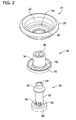
- FIG. 2 is an exploded view of the valve showing a mounting cup, a seal, and a stem of the valve;
- FIG. 3 is a cross section of the valve
- FIG. 4A is a cross section of the mounting cup
- FIG. 4B is a cross section of another embodiment of a mounting cup similar to the mounting cup of FIG. 4A ;
- FIG. 5 is a cross section of the seal
- FIG. 6 is a cross section of a container assembly including the valve and a pressurized container to which the valve is attached, the pressurized container being shown partially;
- FIG. 7 is a cross section of a gun dispensing assembly including the valve, the pressurized container to which the valve is attached, a gun collar attached to the pressurized container, and a gun basket of the dispensing gun attached to the gun collar;
- FIG. 8 is a cross section of a second embodiment of a valve
- FIG. 9 is an enlarged cross section of a mounting cup of the second valve embodiment
- FIG. 10 is a cross section of a third embodiment of a valve
- FIG. 11 is an enlarged cross section of a mounting cup of the third valve embodiment
- FIG. 12 is a cross section of a fourth embodiment of a valve
- FIG. 13 is an enlarged cross section of a mounting cup of the fourth valve embodiment
- FIG. 14 is a perspective of a fifth embodiment of a valve
- FIG. 15 is a front elevation of the fifth valve embodiment
- FIG. 16 is cross section of the fifth valve embodiment
- FIG. 17 is an enlarged cross section of a mounting cup of the fifth valve embodiment
- FIG. 18 is cross section of a sixth valve embodiment
- FIG. 19 is a cross section of a conventional valve
- FIG. 20 is a comparison of the conventional valve of FIG. 19 and the present valve of FIG. 10 ;
- FIG. 21 is a graph comparing force necessary to dispense product using the conventional valve of FIG. 19 and the present valve of FIG. 10 ;
- FIG. 22 shows the dimensions of valves after crimping
- FIG. 23 is a graph comparing the variation in tip position of the conventional valve of FIG. 19 and the present valve of FIG. 14 at various crimp dimensions;
- FIG. 24 is a perspective of a seventh valve embodiment
- FIG. 25 is an enlarged cross section of a mounting cup of the seventh valve embodiment
- FIG. 26 is a perspective of an eighth valve embodiment
- FIG. 27 is an enlarged cross section of a mounting cup of the eighth valve embodiment taken in a plane including opposite concave radial portions of a bottom wall of the mounting cup;
- FIG. 28 is an enlarged cross section of the mounting cup of the eighth valve embodiment taken in a plane including opposite convex radial portions of a bottom wall of the mounting cup;
- FIG. 29 is a perspective of an ninth valve embodiment
- FIG. 30 is an enlarged cross section of a mounting cup of the ninth valve embodiment.
- a valve for dispensing a flowable product e.g., a chemical product or food product
- the valve 10 comprises a mounting cup, generally indicated at 14 ; a stem, generally indicated at 16 ; and a seal (e.g., a grommet), generally indicated at 18 , attached to the stem and disposed between and interconnecting the stem and the mounting cup.
- a pressurized container 20 e.g., an aerosol container
- valve 10 is shown in its pre-attached configuration, meaning that the valve is assembled but is not attached to a pressurized container.
- valve 10 is shown in its attached, closed configuration, meaning that the valve is attached to the pressurized container 20 but the valve is closed (e.g., non-actuated).
- valve 10 is shown in its attached, open configuration, meaning that the valve is attached to the pressurized container 20 and the valve has been opened (e.g., actuated), such as by a dispensing gun as shown.
- valve 10 in the drawings provides the point of reference for the terms defining relative locations and positions of structures and components of the valve, including but not limited to the terms “upper,” “lower,” “top,” and “bottom,” “upward,” and “downward,” as used throughout the present disclosure.
- the mounting cup 14 which may be formed from a piece of metal (e.g., tin plate steel, stainless steel or aluminum), has a generally cylindrical sidewall 22 defining an axis A of the mounting cup 14 .
- substantially an entirety of the sidewall 22 is generally parallel to the axis A of the mounting cup 14 when the valve is in its pre-attached configuration, as shown in FIG. 3 , though in other embodiments the sidewall may be tapered.
- a portion of the sidewall 22 bulges radially outward relative to the axis A to secure the valve to the container.
- the mounting cup 14 further includes a bottom wall, generally indicated at 24 , extending radially inward from adjacent a lower end of the sidewall 22 .
- a central portion 26 of the bottom wall 24 defines a cylindrical opening 28 , also known as a pierce hole, through which the seal 18 and the stem 16 extend.
- the central portion 26 of the bottom wall 24 extends upward to define a collar or ferrule surrounding the seal 18 .
- the opening 28 has an axial length extending between open upper and lower ends of the collar or ferrule.
- the central portion 26 may not extend upward to define a collar or ferrule. Instead, the central portion 26 may be substantially planar and the opening 28 may extend therethrough and have an axial length corresponding to the thickness of the central portion.
- the configurations of the bottom wall 24 and the central portion 26 are explained in more detail below.
- the mounting cup 14 is configured for reception into an opening of the container 20 , such as an opening in a top of the container 20 (as shown in FIG. 6 ) or a bottom of the container, and an upper curled lip 29 at an upper end of the sidewall 22 mates with the bead (curl) 30 of the container.
- the valve 10 is then secured to the container by crimping (clinching), for example.
- the seal 18 comprises an elongate neck portion 34 defining a longitudinal lumen 36 through which the stem 16 is received, as explained below.
- the lumen 36 is generally coaxial with the axis A of the mounting cup 14 .
- a lower portion of the seal 18 underlies the bottom wall 24 of the mounting cup 14 and includes an annular flange portion 40 and seat portion 42 at a lower end of the seal defining a seat for the valve stem 16 .
- the annular flange portion 40 is normally pressed against the bottom wall 24 of the mounting cup 14 to form a leak proof seal therebetween when the valve 10 is secured to the container 20 ( FIG. 6 ).
- An external seal bead 46 extends radially outward from the neck portion 34 of the seal 18 .
- at least one internal seal bead 48 may extend inward from an inner surface of the neck portion 34 .
- the external, annular seal bead 46 engages an upper peripheral edge of the central portion 26 of the mounting cup 14 to secure the seal 18 to the mounting cup.
- the internal seal bead 48 when included, presses against the stem 16 to form a seal therebetween, otherwise the seal may be obtained by an interference fit between the inner wall of lumen 36 and the stem 16 .
- the seal 18 may comprise a thermoset rubber (e.g., vulcanized rubber, such as vulcanized neoprene rubber) or thermoplastic elastomer (e.g., thermoplastic polyurethane), and may be formed by injection molding, compression molding, or transfer molding, for example.
- a thermoset rubber e.g., vulcanized rubber, such as vulcanized neoprene rubber
- thermoplastic elastomer e.g., thermoplastic polyurethane
- the stem 16 comprises an elongate tubular stem body 52 with an outlet 54 and inlet(s) 56 at the upper and lower ends thereof, respectively, and a disc 60 (or button) at the lower end of the stem body.
- the stem body 52 fits snugly within the longitudinal lumen 36 defined by the seal 18 and engages the internal seal bead 48 , when included in the design, to form a leak proof seal therebetween.
- An upper portion of the stem body 52 is exposed and extends through an open upper end of the seal 18 .
- the upper portion of the stem body 52 includes an annular shoulder 62 extending laterally outward from the stem body and overlying and engaging the upper end of the seal 18 .
- the disc 60 seats against the seat portion 42 of the seal 18 to form a leak proof seal therebetween when the valve 10 is closed (e.g., in a non-actuated configuration).
- the upper portion of the stem body 52 above annular shoulder 62 , may include a thread (or other connector or connecting structure) for connecting the stem 16 to an actuator or other device.
- the upper portion of the stem body 52 may include a thread onto which an actuation device may be attached when the valve 10 is used as a tilt valve, as generally known in the art.
- the valve may be used without any additional actuator and may include a component for profiling or shaping the dispensed product.
- the disc 60 of the stem 16 is movable away from the seat portion 42 of the seal 18 to open the valve (e.g., move the valve to an actuated configuration) to allow flowable product in the container 20 , via pressure in the container, to flow between the disc and the seat portion and into the inlet(s) 56 of the stem 16 .
- the valve 10 may function as a “vertically actuated” valve, or alternatively, as a “tilt” valve, depending on the actuator used to operate the valve.
- an axial force is applied to the stem 16 (e.g., the shoulder 62 of the stem) to unseat the disc 60 from the seat portion 42 of the seal 18 , as shown in FIG. 7 and described in more detail below.
- a force is applied to the side of stem 16 to rotate or pivot the stem and unseat the disc 60 from the seat portion 42 , as is generally known in the art.
- an annular side-to-bottom transition portion, generally indicated at 66 , of the mounting cup 14 is disposed between the lower end of the sidewall 22 and the bottom wall 24 thereof.
- the side-to-bottom transition portion 66 curves inward (e.g., is radiused) from the lower end of the sidewall 22 to the bottom wall 24 .
- the side-to-bottom transition portion 66 has an upper boundary (or extent) defined by an upper, annular radius line defining upper radius line plane RL 1 transverse to the axis A, and a lower boundary (or extent) defined by a lower, annular radius line RL 2 defining lower radius plane RL 2 transverse to the axis A.
- the bottom wall 24 has an annular outer radial portion 68 extending radially inward from the side-to-bottom transition portion 66 , and an annular inner radial portion 70 extending radially inward from adjacent an inner radial edge of the outer radial portion toward the axis A of the mounting cup and the central portion 26 .
- the outer radial portion 68 is generally flat and extends generally orthogonal to the axis A of the mounting cup 14 when the valve 10 is in its pre-attached configuration ( FIGS. 3 and 4A ). When the valve 10 is attached to the container, such as shown in FIG.
- the outer radial portion 68 of bottom wall 24 may not remain in a flat position orthogonal to the axis A of the mounting cup 14 but may extend upward or downward from the sidewall 22 at an angle greater than or less than 90 degrees relative to the axis A of the mounting cup.
- the outer radial portion may be of other configurations and orientations both in its pre-attached and attached configurations.
- the inner radial portion 70 extends downward at an angle ⁇ relative to a plane extending orthogonal to the axis A of the mounting cup 14 .
- this angle ⁇ may measure from greater than 0 degrees (e.g., about 5 degrees) to about 90 degrees, or may be an acute angle measuring from about 25 degrees to about 50 degrees, and in one example, about 45 degrees.
- the inner radial portion 70 may extend at an angle measuring 0 degrees.
- An annular first bottom transition portion 76 is disposed between and interconnects the inner and outer radial portions 68 , 70 , respectively.
- the first bottom transition portion 76 curves downward (e.g., has a concave radius when viewed from the bottom) from the outer radial portion 68 to the inner radial portion 70 .
- An annular second bottom transition portion 78 is disposed between and interconnects an inner radial edge of the inner radial portion 70 and the central portion 26 .
- the second bottom transition portion 78 curves upward (e.g., has a convex radius when viewed from the bottom).
- the upper end of the central portion 26 defining the opening 28 (e.g., the end of the central portion that is engaged by the external seal bead 46 in the illustrated embodiment lies in a plane P 1 ) is at (e.g., coplanar with) or below (e.g., entirely below) the upper radius line plane RL 1 .
- the upper end of the central portion 26 defining the opening 28 (e.g., the end of the central portion that is engaged by the external seal bead 46 in the illustrated embodiment lies in a plane P 1 ) is at (e.g., coplanar with) or below (e.g., entirely below) the lower radius line plane RL 2 .
- the upper end of the central portion 26 defining the opening 28 (e.g., the end of the central portion that is engaged by the external seal bead 46 in the illustrated embodiment lies in a plane P 1 ) is at (e.g., coplanar with) or below (e.g., entirely below) an imaginary line L 1 perpendicular to the central axis A and tangent to a lower portion of an imaginary circle C 1 defined by the radius of the annular sidewall-bottom transition portion 66 .
- the imaginary line L 1 and the lower radius line plane RL 2 are coplanar, although in other embodiments, the imaginary line L 1 and the lower radius line RL 2 may not be coplanar (i.e., may be spaced apart along the axis A).
- the plane P 1 is below (e.g., entirely below) the line L 1 and lower radius line plane RL 2 .
- a distance d 0 between the upper radius line plane RL 1 and the plane P 1 may be from about 0.0 mm to about 25.0 mm, or from about 0.25 mm to about 10.0 mm, or from about 0.25 mm to about 2.0 mm, or from about 0.1 mm to about 2.5 mm, or about 1.0 mm, or about 0.50 mm.
- a distance d 1 between the imaginary line L 1 and the plane P 1 may be from about 0.0 mm to about 25.0 mm, or from about 0.25 mm to about 10.0 mm, or from about 0.25 mm to about 2.0 mm, or from about 0.1 mm to about 2.5 mm, or about 1.0 mm, or about 0.50 mm.
- a distance d 2 between the lower radius line plane RL 2 and the plane P 1 may be from about 0.0 mm to about 25.0 mm, or from about 0.25 mm to about 10.0 mm, or from about 0.25 mm to about 2.0 mm, or from about 0.1 mm to about 2.5 mm, or about 1.0 mm, or about 0.50 mm.
- the upper end of the central portion 26 ′ defining the opening 28 ′ (e.g., the end of the central portion that is engaged by the external seal bead 46 in the illustrated embodiment lies in a plane P 2 ) is slightly above the lower radius line plane RL 4 and/or the line L 1 ′ perpendicular to the central axis A′ and tangent to the lower portion of the imaginary circle C 1 ′ defined by the radius of the annular sidewall-bottom transition portion 66 .
- a distance d 3 between the imaginary line L 1 ′ (and the lower radius line plane RL 4 ) and the plane P 2 in which the upper end of the central portion 26 ′ lies may be from about 0.000 in (0.000 mm) to about 0.040 in (1.016 mm) (e.g., no greater than 0.040 in).
- the plane P 2 is below (e.g., entirely below) the upper radius line plane RL 3 . Accordingly, the plane P 2 is intermediate the upper radius line plane RL 3 and the imaginary line L 1 ′ (and the lower radius line plane RL 4 ) along the axis A.
- the inner radial portion 70 ′ extends downward at an angle ⁇ ′ relative to a plane extending orthogonal to the axis A′ of the mounting cup 14 ′ that is less than the angle ⁇ of the first mounting cup 14 .
- a gun basket, generally indicated at 80 of a dispensing gun is attached (e.g., threaded onto) a gun collar (broadly, a connector), generally indicated at 82 , which is attached to the valve 10 after the valve is attached to the container 20 .
- a gun collar also, a connector
- the gun basket 80 is threaded onto the gun collar 82 , the upper portion of the stem 16 and the neck portion 34 of the seal 18 enter a hub 84 of the gun basket.
- An internal shoulder of the hub engages the shoulder 62 of the stem 16 to drive axial movement of the stem relative to the seal 18 and unseat the stem disc 60 from the seat portion 42 of the seal.
- the neck portion 34 of the seal 18 compresses between the shoulder 62 of the stem and the upper peripheral edge of the central portion 26 , and the neck portion 34 of the seal bulges outward inside the hub 84 to create a leak proof seal therein. Because the upper end of the central portion 26 is at or below at least a junction of the sidewall 22 and the annular sidewall-bottom transition portion 66 , such as at or below (e.g., below) an entirety of the outer radial portion 68 of the bottom wall 24 as can be seen from FIG.
- the gun basket hub 84 is of a design that allows it to approach the bottom wall 24 when the gun collar 82 is threaded fully into the gun basket 80 , the gun collar 82 will “bottom out” in the gun basket 80 before the gun basket hub 82 engages the external seal bead 46 . This inhibits the external sealing bead 46 from being pinched between the hub 84 and the upper peripheral edge of the central portion 26 , thereby inhibiting the external seal bead from shearing off.
- FIGS. 8 and 9 another embodiment of a valve constructed according to the teachings of the present disclosure is generally indicated at reference numeral 110 .
- This valve 110 is similar to the first valve 10 , with differences between the valves being disclosed below. Identical components and structures are indicated by corresponding reference numerals, and similar, but not identical, components and structures are indicated by corresponding reference numerals plus 100. Unless otherwise indicated, the teachings and disclosure set forth above with respect to the first valve 10 apply equally to the present valve 110 .
- the main differences between the present valve 110 and the first valve 10 is the respective radial dimensions of the outer and inner radial portions 168 , 170 of the bottom wall 124 of the present mounting cup 114 and the relationship between the flanges 40 of the seal 18 and the mounting cup.
- the radial dimension of the outer radial portion 168 is shortened and the radial dimension of the inner radial portion 170 is extended.
- the flanges 40 of the seal 18 extend along the inner radial portion 170 but do not extend to the outer radial portion 168 .
- the downward slope of the inner radial portion may be less than the slope of the inner radial portion 70 of the first valve.
- the inner radial portion 170 may extend downward at an angle ⁇ 1 relative to a plane extending orthogonal to the axis A 1 of the mounting cup 114 that is less than the angle ⁇ of the first valve 10 .
- FIGS. 10 and 11 another embodiment of a valve constructed according to the teachings of the present disclosure is generally indicated at reference numeral 210 .
- the valve 210 is similar to the first valve 10 .
- Identical components and structures are indicated by corresponding reference numerals, and similar, but not identical components and structures, are indicated by corresponding reference numerals plus 200.
- the seal 218 is similar to seal 18 , except that the seal 218 includes a depending terminal flange 241 at the outer end of the flange 240 .
- the terminal flange 241 is generally annular shaped and extends around the flange 240 .
- the terminal flange 241 extends generally downward from the flange 240 to define an annular groove 242 of the seal. In use, pressure within the can is exerted against the flange 240 within the annular groove 242 to facilitate sealing of the flange against the radial portion 269 of the bottom wall 224 .
- an annular side-to-bottom transition portion, generally indicated at 266 , of the mounting cup 214 is disposed between the lower end of the sidewall 22 and the bottom wall 224 thereof.
- the side-to-bottom transition portion 266 curves inward (e.g., is radiused) from the lower end of the sidewall 22 to the bottom wall 224 .
- the side-to-bottom transition portion 266 has an upper boundary (or extent) defined by an upper, annular radius line defining upper radius line plane RL 5 transverse to the axis A 2 , and a lower boundary (or extent) defined by a lower, annular radius line RL 6 defining lower radius plane RL 6 transverse to the axis A 2 .
- the bottom wall 224 has an annular radial portion 269 extending radially inward from the side-to-bottom transition portion 266 to the central portion 26 of the bottom wall.
- the radial portion 269 extends downward at a constant angle ⁇ 2 (e.g., a constant slope) relative to a plane extending orthogonal to the axis A 2 of the mounting cup 214 when the valve 210 is in its pre-attached configuration.
- this angle ⁇ 2 may measure from about 5 degrees to about 90 degrees, or may be an acute angle measuring from about 25 degrees to about 50 degrees, and in one example, about 30 degrees.
- the radial portion 269 of bottom wall 224 may or may not remain at this pre-attached angle ⁇ 2 .
- the radial portion 269 may extend upward or downward from the sidewall 22 at an angle greater than or less than its pre-attached angle ⁇ 2 .
- the radial portion 269 may be of other configurations and orientations both in its pre-attached and attached configurations.
- the upper end of the central portion 26 defining the opening 28 (e.g., the end of the central portion that is engaged by the external seal bead 46 in the illustrated embodiment lies in a plane P 3 ) is at (e.g., coplanar with) or below (e.g., entirely below) the upper radius line plane RL 5 .
- the upper end of the central portion 26 defining the opening 28 (e.g., the end of the central portion that is engaged by the external seal bead 46 in the illustrated embodiment lies in a plane P 3 ) is at (e.g., coplanar with) or below (e.g., entirely below) the lower radius line plane RL 6 .
- the upper end of the central portion 26 defining the opening 28 (e.g., the end of the central portion that is engaged by the external seal bead 46 in the illustrated embodiment lies in a plane P 3 ) is at (e.g., coplanar with) or below (e.g., entirely below) an imaginary line L 2 perpendicular to the central axis A 2 and tangent to a lower portion of an imaginary circle C 2 defined by the radius of the annular sidewall-bottom transition portion 266 .
- the imaginary line L 2 and the lower radius line plane RL 6 are coplanar, although in other embodiments, the imaginary line L 2 and the lower radius line RL 6 may not be coplanar (i.e., spaced apart along the axis A 2 ).
- the plane P 3 is below (e.g., entirely below) the line L 2 and lower radius line plane RL 6 .
- a distance d 4 between the upper radius line plane RL 5 and the plane P 2 may be from about 0.0 mm to about 25.0 mm, or from about 0.25 mm to about 10.0 mm, or from about 0.25 mm to about 2.0 mm, or from about 0.1 mm to about 2.5 mm, or about 1.0 mm, or about 0.50 mm.
- a distance d 5 between the imaginary line L 2 and the plane P 3 may be from about 0.0 mm to about 25.0 mm, or from about 0.25 mm to about 10.0 mm, or from about 0.1 mm to about 2.5 mm, or from about 0.25 mm to about 2.0 mm, or about 1.0 mm, or about 0.50 mm.
- a distance d 6 between the lower radius line plane RL 6 and the plane P 2 may be from about 0.0 mm to about 25.0 mm, or from about 0.25 mm to about 10.0 mm, or from about 0.25 mm to about 2.0 mm, or from about 0.1 mm to about 2.5 mm, or about 1.0 mm, or about 0.50 mm.
- FIGS. 12 and 13 another embodiment of a valve constructed according to the teachings of the present disclosure is generally indicated at reference numeral 310 .
- This valve 310 is similar to the third valve 210 , with differences between the valves being disclosed below. Identical components and structures are indicated by corresponding reference numerals, and similar, but not identical, components and structures are indicated by corresponding reference numerals plus 100. Unless otherwise indicated, the teachings and disclosure set forth above with respect to the third valve 210 apply equally to the present valve 310 .
- the main differences between the present valve 310 and the third valve 210 is the radial portion 369 of the bottom wall 324 is arcuate shaped and curves upward along its length (i.e., is concave when viewed from bottom), unlike the radial portion 269 of the bottom wall 224 of the third valve 210 which has a substantially constant slope or angle extending downward.
- Another difference is that an imaginary circle C 3 defined by the radius of the annular sidewall-bottom transition portion 366 is smaller than the imaginary circle C 2 .
- the upper end of the central portion 26 defining the opening 28 (e.g., the end of the central portion that is engaged by the external seal bead 46 in the illustrated embodiment lies in a plane P 4 ) is at (e.g., coplanar with) or below (e.g., entirely below) the upper radius line plane RL 7 .
- the upper end of the central portion 26 defining the opening 28 (e.g., the end of the central portion that is engaged by the external seal bead 46 in the illustrated embodiment lies in a plane P 4 ) is at (e.g., coplanar with) or below (e.g., entirely below) the lower radius line plane RL 8 .
- the upper end of the central portion 26 defining the opening 28 (e.g., the end of the central portion that is engaged by the external seal bead 46 in the illustrated embodiment lies in a plane P 4 ) is at (e.g., coplanar with) or below (e.g., entirely below) an imaginary line L 3 perpendicular to the central axis A 3 and tangent to a lower portion of an imaginary circle C 3 defined by the radius of the annular sidewall-bottom transition portion 366 .
- the imaginary line L 3 and the lower radius line plane RL 8 are coplanar, although in other embodiments, the imaginary line L 3 and the lower radius line RL 8 may not be coplanar (i.e., spaced apart along the axis A 3 ).
- the plane P 4 is below (e.g., entirely below) the line L 3 and lower radius line plane RL 8 .
- a distance d 7 between the upper radius line plane RL 7 and the plane P 4 may be from about 0.0 mm to about 25.0 mm, or from about 0.25 mm to about 10.0 mm, or from about 0.25 mm to about 2.0 mm, or from about 0.1 mm to about 2.5 mm, or about 1.0 mm, or about 0.50 mm.
- a distance d 8 between the imaginary line L 3 and the plane P 4 may be from about 0.0 mm to about 25.0 mm, or from about 0.25 mm to about 10.0 mm, or from about 0.25 mm to about 2.0 mm, or from about 0.1 mm to about 2.5 mm, or about 1.0 mm, or about 0.50 mm.
- a distance d 9 between the lower radius line plane RL 8 and the plane P 4 may be from about 0.0 mm to about 25.0 mm, or from about 0.25 mm to about 10.0 mm, or from about 0.25 mm to about 2.0 mm, or from about 0.1 mm to about 2.5 mm, or about 1.0 mm, or about 0.50 mm.
- FIGS. 14-17 another embodiment of a valve constructed according to the teachings of the present disclosure is generally indicated at reference numeral 410 .
- This valve 410 is similar to the third valve 210 , with differences between the valves being disclosed below. Identical components and structures are indicated by corresponding reference numerals, and similar, but not identical, components and structures are indicated by corresponding reference numerals plus 200. Unless otherwise indicated, the teachings and disclosure set forth above with respect to the third valve 210 apply equally to the present valve 410 .
- the seal 418 is similar to seal 218 , except that the terminal flange 441 at the outer end of the flange 440 flares outward.
- the terminal flange 441 is generally annular shaped and extends around the flange 440 .
- the terminal flange 441 extends generally downward from the flange 240 and flares outward to define an annular groove 442 of the seal. In use, pressure within the can is exerted against the flange 440 within the annular groove 442 to facilitate sealing of the flange against the radial portion 469 of the bottom wall 424 .
- the radial portion 469 of the bottom wall 424 is arcuate shaped, extends downward and curves downward along its length (i.e., is convex or dome-shaped when viewed from bottom), unlike the radial portion 269 of the bottom wall 224 of the third valve 210 which has a substantially constant slope or angle extending downward.
- the bottom wall may have a radius of about 0.450 in (1.143 cm).
- the upper end of the central portion 26 defining the opening 28 (e.g., the end of the central portion that is engaged by the external seal bead 46 in the illustrated embodiment lies in a plane P 5 ) is at (e.g., coplanar with) or below (e.g., entirely below) the upper radius line plane RL 9 .
- the upper end of the central portion 26 defining the opening 28 (e.g., the end of the central portion that is engaged by the external seal bead 46 in the illustrated embodiment lies in a plane P 5 ) is at (e.g., coplanar with) or below (e.g., entirely below) the lower radius line plane RL 10 .
- the upper end of the central portion 26 defining the opening 28 (e.g., the end of the central portion that is engaged by the external seal bead 46 in the illustrated embodiment lies in a plane P 5 ) is at (e.g., coplanar with) or below (e.g., entirely below) an imaginary line L 4 perpendicular to the central axis A 4 and tangent to a lower portion of an imaginary circle C 4 defined by the radius of the annular sidewall-bottom transition portion 466 .
- the imaginary line L 4 and the lower radius line plane RL 10 are coplanar, although in other embodiments, the imaginary line L 4 and the lower radius line RL 10 may not be coplanar (i.e., spaced apart along the axis A 4 ).
- the plane P 5 is below (e.g., entirely below) the line L 4 and lower radius line plane RL 10 .
- a distance d 10 between the upper radius line plane RL 9 and the plane P 5 may be from about 0.0 mm to about 25.0 mm, or from about 0.25 mm to about 10.0 mm, or from about 0.25 mm to about 2.0 mm, or from about 0.1 mm to about 2.5 mm, or about 1.0 mm, or about 0.50 mm.
- a distance d 11 between the imaginary line L 4 and the plane P 5 may be from about 0.0 mm to about 25.0 mm, or from about 0.25 mm to about 10.0 mm, or from about 0.25 mm to about 2.0 mm, or from about 0.1 mm to about 2.5 mm, or about 1.0 mm, or about 0.50 mm.
- a distance d 12 between the lower radius line plane RL 10 and the plane P 5 may be from about 0.0 mm to about 25.0 mm, or from about 0.25 mm to about 10.0 mm, or from about 0.25 mm to about 2.0 mm, or from about 0.1 mm to about 2.5 mm, or about 1.0 mm, or about 0.50 mm.
- valve 410 ′ is identical to the valve 410 , except that the stem 16 , which is a tilt stem, is replaced with a “vertically actuated” stem (or gun valve stem) 16 ′. All other components of the valve 410 ′ are identical to the corresponding components of the valve 410 .
- each of the other valve embodiments of the present disclosure provide the same advantages as set forth above with respect to the first valve 10 . Accordingly, the advantages set forth above with respect to the first valve 10 apply equally to the other valve embodiments.
- each of the valve embodiments of the present disclosure provides the following advantages over a conventional valve.
- a typical prior art valve is generally indicated at reference numeral 500 .
- the illustrated prior art valve is a tilt valve including a tilt stem 501 , a seal 503 , and a mounting cup 505 .
- the bottom wall 507 of the mounting cup defines a cylindrical opening 509 , also known as a pierce hole, through which the seal 503 and the stem 501 extend, and the plane P 6 in which the upper end of the pierce hole is disposed is above the lower radius line plane RL 11 and an imaginary line L 5 perpendicular to the central axis A 5 and tangent to a lower portion of an imaginary circle C 5 defined by the radius of the annular sidewall-bottom transition portion 513 .
- the upper end of the pierce hole 509 is also disposed is above the upper radius line plane RL 12 bounding the annular sidewall-bottom transition portion 513 .
- FIG. 20 a side-by-side comparison of the conventional valve 500 of FIG. 19 and a valve 210 ′ of the present disclosure is illustrated.
- the valve 210 ′ includes the mounting cup 214 and seal 218 of the valve 210 of FIG. 10 .
- a stem 16 ′′ is different than the stem 16 of the valve 210 .
- the stem 16 ′′ is identical to the stem 501 of the conventional valve 500 .
- the valve 210 ′ is shown for illustrative purposes with the understanding that each of the valve embodiments disclosed above herein provides the same advantage over the conventional valve 500 , as set forth below.
- the moment arm MA 2 of the present valve 210 ′ is greater (i.e., longer) than the moment arm of the conventional valve 500 .
- the force F 2 i.e., tilt force
- Table 1 shows the force required to open the conventional valve to dispense a product.
- Table 2 shows the force required to open the present valve to dispense a product.
- FIG. 21 is a graph plotting the data from Tables 1 and 2.
- the present valve 210 ′ has greater moment arm due to the fact that the moment center CM 2 of the stem of the present valve is “lower” than the moment center CM 1 of the stem of the conventional valve, which is due to the pierce hole of the present valve being “lower” than the pierce hole of the conventional valve.
- the lengths L 1 , L 2 of the stems 501 , 16 ′′ of the respective conventional valve 500 and the present valve 210 ′ are substantially equal (in fact, the stems are identical).
- the distances L 3 , L 4 that the stems 501 , 16 ′′ extend above the upper portion of the corresponding cup are also substantially equal.
- valves 500 , 210 ′ are substantially equal. Accordingly, certain dimensions of the valves 500 , 210 ′ are substantially the same so that the present valve can be interchangeably used in place of the conventional valve without the need to change the designs of container (e.g., aerosol can) and/or packaging, such as lids and boxes.
- container e.g., aerosol can
- packaging such as lids and boxes.
- valves are typically crimped onto aerosol cans in order to create a seal between the can and the valve.
- the valve cup is deformed. This deformation of the valve cup causes the valve tip to change its position (generally known as “rise”). This can be an issue for valves used in packaging configurations that dock with the tip of the valve.
- gun valves for one component polyurethane foam are also examples of dispenser caps that connect with the tip of the valve.
- valve tip position is affected by the crimp.
- Crimp dimensions are generally measured in depth from the top of the cup to the centerline of the crimp and diameter of the crimp as shown in FIG. 22 .
- a typical crimp dimension would be specified as 0.205 in ⁇ 1.055 in (5.207 mm ⁇ 26.797 mm), which would be a depth of 0.205 in (5.207 mm) and a diameter of 1.055 in (26.797 mm).
- the present valve 410 is less susceptible to variations in tip height caused by variation in crimp dimensions as compared to the conventional valve 500 of FIG. 19 . That is, the variation in the tip position, after crimping, as a function of crimp depth and diameter is reduced as compared to the conventional valve 500 of FIG. 19 .
- Table 3 includes data as to the tip position for various crimp dimensions for the conventional valve 500 and the present valve 410 illustrated in FIG. 14 .
- FIG. 23 is a graph plotting the data in Table 3.
- the mounting cup may be formed from sheet metal having a thickness of less than 0.016 in (0.406 mm) and greater than or equal to 0.005 in (0.127 mm).
- the sheet metal may be steel or other metal material.
- the valve 410 of FIG. 14 may be formed from steel sheet metal having a thickness of about 0.010 in (0.254 mm), such that the mounting cup 414 resists deformation and does not significantly deform in use under a pressure of at least about 180 psi.
- valve 610 is similar to the third valve 210 , with differences between the valves being disclosed below. Identical components and structures are indicated by corresponding reference numerals, and similar, but not identical, components and structures are indicated by corresponding reference numerals plus 400. Unless otherwise indicated, the teachings and disclosure set forth above with respect to the third valve 210 apply equally to the present valve 610 .
- the valve stem 16 and the seal 18 are identical to the stem and seal of the third valve 210 .
- the main difference between the present valve 610 and the third valve 210 is the mounting cup 614 , and more specifically, the bottom wall 624 .
- the annular sidewall-bottom transition portion 666 has a greater radius of curvature compared to the annular sidewall-bottom transition portion 266 .
- the radial portion 669 has a constant slope like the third valve 210 .
- the upper end of the central portion 26 defining the opening 28 (e.g., the end of the central portion that is engaged by the external seal bead in the illustrated embodiment lies in a plane P 7 ) is at (e.g., coplanar with) or below (e.g., entirely below) the upper radius line plane RL 13 .
- the upper end of the central portion 26 defining the opening 28 (e.g., the end of the central portion that is engaged by the external seal bead in the illustrated embodiment lies in a plane P 7 ) is at (e.g., coplanar with) or below (e.g., entirely below) the lower radius line plane RL 14 .
- the upper end of the central portion 26 defining the opening 28 is below both the upper radius line plane RL 13 and the lower radius line plane RL 14 .
- a distance d 13 between the upper radius line plane RL 13 and the plane P 7 may be from about 0.0 mm to about 25.0 mm, or from about 0.25 mm to about 10.0 mm, or from about 0.25 mm to about 2.0 mm, or from about 0.1 mm to about 2.5 mm, or about 1.0 mm, or about 0.50 mm.
- a distance d 14 between the lower radius line plane RL 14 and the plane P 7 may be from about 0.0 mm to about 25.0 mm, or from about 0.25 mm to about 10.0 mm, or from about 0.25 mm to about 2.0 mm, or from about 0.1 mm to about 2.5 mm, or about 1.0 mm, or about 0.50 mm.
- FIGS. 26-28 another embodiment of a valve constructed according to the teachings of the present disclosure is generally indicated at reference numeral 710 .
- This valve 710 is similar to the third valve 210 , with differences between the valves being disclosed below. Identical components and structures are indicated by corresponding reference numerals, and similar, but not identical, components and structures are indicated by corresponding reference numerals plus 500. Unless otherwise indicated, the teachings and disclosure set forth above with respect to the third valve 210 apply equally to the present valve 710 .
- the valve stem 16 and the seal 18 are identical to the stem and seal of the third valve 210 .
- the main difference between the present valve 610 and the third valve 210 is the mounting cup 714 , and more specifically, the bottom wall 724 .
- the bottom wall 724 has alternating concave radial segments 726 (e.g., grooves) and convex radial segments 728 (e.g., ridges), such that the radial portion 769 is corrugated with a plurality of radial folds.
- a sectional view taken through opposite concave radial segments 726 is illustrated in FIG. 27
- a sectional view taken through opposite convex radial segments 728 is illustrated in FIG. 28 . It is believed the corrugated bottom wall 725 increases the rigidity to the bottom wall.
- the upper end of the central portion 726 defining the opening 728 (e.g., the end of the central portion that is engaged by the external seal bead in the illustrated embodiment lies in a plane P 8 ) is at (e.g., coplanar with) or below (e.g., entirely below) the upper radius line plane RL 15 .
- the upper end of the central portion 726 defining the opening 728 (e.g., the end of the central portion that is engaged by the external seal bead in the illustrated embodiment lies in a plane P 8 ) is at (e.g., coplanar with) or below (e.g., entirely below) the lower radius line plane RL 16 .
- the upper end of the central portion 726 defining the opening 728 (e.g., the end of the central portion that is engaged by the external seal bead in the illustrated embodiment lies in a plane P 8 ) is at (e.g., coplanar with) or below (e.g., entirely below) an imaginary line L 6 perpendicular to the central axis A 5 and tangent to a lower portion of an imaginary circle C 6 defined by the radius of the annular sidewall-bottom transition portion 766 .
- the imaginary line L 6 and the lower radius line plane RL 16 are coplanar, although in other embodiments, the imaginary line L 6 and the lower radius line may not be coplanar (i.e., spaced apart along the axis A 5 ).
- the plane P 8 is below (e.g., entirely below) the line L 6 and lower radius line plane RL 16 .
- a distance d 15 between the upper radius line plane RL 15 and the plane P 8 may be from about 0.0 mm to about 25.0 mm, or from about 0.25 mm to about 10.0 mm, or from about 0.25 mm to about 2.0 mm, or from about 0.1 mm to about 2.5 mm, or about 1.0 mm, or about 0.50 mm.
- a distance d 16 between the imaginary line L 6 (and the lower radius line plane RL 16 ) and the plane P 8 may be from about 0.0 mm to about 25.0 mm, or from about 0.25 mm to about 10.0 mm, or from about 0.25 mm to about 2.0 mm, or from about 0.1 mm to about 2.5 mm, or about 1.0 mm, or about 0.50 mm.
- FIGS. 29 and 30 another embodiment of a valve constructed according to the teachings of the present disclosure is generally indicated at reference numeral 810 .
- This valve 810 is similar to the third valve 210 , with differences between the valves being disclosed below. Identical components and structures are indicated by corresponding reference numerals, and similar, but not identical, components and structures are indicated by corresponding reference numerals plus 600. Unless otherwise indicated, the teachings and disclosure set forth above with respect to the third valve 210 apply equally to the present valve 810 .
- the valve stem 16 and the seal 18 are identical to the stem and seal of the third valve 210 .
- the main difference between the present valve 810 and the third valve 210 is the mounting cup 814 , and more specifically, the bottom wall 824 .
- the bottom wall 824 has a plurality of ribs 832 formed on the bottom wall 824 , more specifically, the inner radial portion 869 of the bottom wall.
- the ribs 832 project upward from the inner radial portion 869 and corresponding grooves 834 are formed on the underside of the inner radial portion.
- the ribs may project downward and corresponding grooves may be formed on the upper side of the inner radial portion.
- the ribs 832 are spaced apart from one another around the inner radial portion 869 .
- the other features and components of the mounting cup 814 may be identical to the mounting cup 214 , and the description of the mounting cup 214 set forth above applies equally to the present mounting cup 814 .
Landscapes
- Engineering & Computer Science (AREA)
- Mechanical Engineering (AREA)
- Chemical & Material Sciences (AREA)
- Dispersion Chemistry (AREA)
- General Engineering & Computer Science (AREA)
- Containers And Packaging Bodies Having A Special Means To Remove Contents (AREA)
Priority Applications (1)
| Application Number | Priority Date | Filing Date | Title |
|---|---|---|---|
| US14/797,521 US9446894B2 (en) | 2014-07-14 | 2015-07-13 | Valve for pressurized container |
Applications Claiming Priority (3)
| Application Number | Priority Date | Filing Date | Title |
|---|---|---|---|
| US201462024231P | 2014-07-14 | 2014-07-14 | |
| US201562158300P | 2015-05-07 | 2015-05-07 | |
| US14/797,521 US9446894B2 (en) | 2014-07-14 | 2015-07-13 | Valve for pressurized container |
Publications (2)
| Publication Number | Publication Date |
|---|---|
| US20160009482A1 US20160009482A1 (en) | 2016-01-14 |
| US9446894B2 true US9446894B2 (en) | 2016-09-20 |
Family
ID=53761452
Family Applications (1)
| Application Number | Title | Priority Date | Filing Date |
|---|---|---|---|
| US14/797,521 Active US9446894B2 (en) | 2014-07-14 | 2015-07-13 | Valve for pressurized container |
Country Status (8)
| Country | Link |
|---|---|
| US (1) | US9446894B2 (sl) |
| EP (1) | EP3169609B1 (sl) |
| CN (1) | CN106660690A (sl) |
| CA (1) | CA2951505C (sl) |
| HU (1) | HUE043630T2 (sl) |
| PL (1) | PL3169609T3 (sl) |
| SI (1) | SI3169609T1 (sl) |
| WO (1) | WO2016009332A1 (sl) |
Cited By (14)
| Publication number | Priority date | Publication date | Assignee | Title |
|---|---|---|---|---|
| US20130334260A1 (en) * | 2010-10-18 | 2013-12-19 | Soudal | Handheld applicator suitable for gun valve containers |
| US20180201417A1 (en) * | 2017-01-17 | 2018-07-19 | Coloright Ltd. | Plastic cap applicator |
| US20190276221A1 (en) * | 2018-03-06 | 2019-09-12 | The Procter & Gamble Company | Multi-piece valve stem for aerosols |
| US11117735B2 (en) | 2019-07-26 | 2021-09-14 | The Procter & Gamble Company | Valve assembly for dispensers |
| US11117736B2 (en) | 2019-07-26 | 2021-09-14 | The Procter & Gamble Company | Valve assembly for dispensers |
| US11172787B2 (en) | 2020-03-04 | 2021-11-16 | Summit Packaging Systems, Inc. | Food product dispenser valve normally biased into closed position |
| WO2021263054A1 (en) * | 2020-06-24 | 2021-12-30 | Clayton Corporation | Valve for dispensing a flowable product from a pressurized container |
| US11358783B2 (en) * | 2018-08-24 | 2022-06-14 | Clayton Corporation | Mounting cup for pressurized container |
| WO2023076471A1 (en) * | 2021-10-28 | 2023-05-04 | Clayton Corporation | Valve seal and valve including same |
| US11674601B2 (en) | 2019-07-26 | 2023-06-13 | The Procter & Gamble Company | Valve assembly for dispensers |
| US11674615B2 (en) | 2019-07-26 | 2023-06-13 | The Procter & Gamble Company | Valve assembly for dispensers |
| EP3898425B1 (en) | 2018-12-20 | 2023-06-21 | Soudal | Improved filling of propellant gas into polyurethane spray cans |
| US11703130B2 (en) | 2019-07-26 | 2023-07-18 | The Procter & Gamble Company | Valve assembly for dispensers |
| US11892084B2 (en) | 2019-07-26 | 2024-02-06 | The Procter & Gamble Company | Valve assembly for dispensers |
Families Citing this family (9)
| Publication number | Priority date | Publication date | Assignee | Title |
|---|---|---|---|---|
| US20060190106A1 (en) | 2001-07-30 | 2006-08-24 | Rockwell Automation Technologies, Inc. | Method for consistent storage of data in an industrial controller |
| US10562697B2 (en) * | 2016-09-14 | 2020-02-18 | Crown Packaging Technology, Inc. | Compact aerosol container |
| CN107336920A (zh) * | 2017-08-06 | 2017-11-10 | 安徽高德韦尔精密部件有限公司 | 阀门密封塞 |
| US10448618B2 (en) | 2017-08-28 | 2019-10-22 | David S. Robbins | Systems, methods and apparatus for monitoring animal health conditions |
| US20190059336A1 (en) * | 2017-08-28 | 2019-02-28 | David S. Robbins | Systems, methods and apparatus for monitoring animal health conditions |
| CN110654727A (zh) * | 2019-03-10 | 2020-01-07 | 安徽高德韦尔精密部件有限公司 | 大流量阀门 |
| FR3098797B1 (fr) * | 2019-07-19 | 2022-01-28 | Promens Sa | Dispositif de bouchage d’un contenant d’un produit liquide à pâteux et recharge fermée par un tel dispositif |
| MX2022000993A (es) * | 2019-07-24 | 2022-02-16 | Lindal France Sas | Copela de valvula para recipiente a presion. |
| FR3099144B1 (fr) * | 2019-07-24 | 2022-01-07 | Lindal France | Valve pour récipient sous pression |
Citations (37)
| Publication number | Priority date | Publication date | Assignee | Title |
|---|---|---|---|---|
| US2703665A (en) * | 1950-12-11 | 1955-03-08 | Dev Res Inc | Locking restrictor for dispensing valves |
| US2704172A (en) | 1949-05-02 | 1955-03-15 | Reddi Wip Inc | Dispensing valves for gas pressure containers |
| US3048307A (en) | 1959-08-24 | 1962-08-07 | Michel David Daniel | Device for dispensing aerated products |
| US3101875A (en) | 1954-06-04 | 1963-08-27 | Michel David Daniel | Valve and dispensing apparatus for pressure containers and the like |
| US3450316A (en) | 1966-05-31 | 1969-06-17 | Du Pont | Aerosol tilt valve for comestibles |
| US3583608A (en) | 1969-05-15 | 1971-06-08 | Scovill Manufacturing Co | Aerosol valve with metering passage |
| US3627179A (en) * | 1969-10-17 | 1971-12-14 | Clayton Corp | Dispensing valve assembly including integrally molded spring |
| US3647120A (en) | 1970-10-28 | 1972-03-07 | Vca Corp | Mixing valve for dispensers |
| US3791561A (en) | 1971-07-08 | 1974-02-12 | Seaquist Valve Co | Pressure relief system for an aerosol dispenser |
| US3918611A (en) | 1971-07-08 | 1975-11-11 | Seaquist Valve Company Div Of | Pressure relief system for an aerosol dispenser |
| US4171074A (en) * | 1977-05-09 | 1979-10-16 | Diamond George B | Pressure responsive tilt valve for pressurized container |
| WO1981001130A1 (en) | 1979-10-18 | 1981-04-30 | Polyfill Ag | Pressurized container |
| US4765516A (en) | 1985-07-15 | 1988-08-23 | Epic Corporation | Aerosol tilt valve mounting cup and assembly |
| US4824075A (en) | 1984-02-14 | 1989-04-25 | Walter Holzboog | Tilt action dispensing valve assembly |
| US4832236A (en) | 1983-08-31 | 1989-05-23 | Metal Box Public Limited Company | Pressurizable containers |
| US4887743A (en) | 1987-06-10 | 1989-12-19 | Blake William S | Aerosol valve |
| US4911336A (en) | 1988-09-23 | 1990-03-27 | Blake William S | Valve with interchangeable components |
| US5016785A (en) | 1985-05-13 | 1991-05-21 | Pittway Corp. | Skirtless mounting cup |
| US5035106A (en) | 1989-12-12 | 1991-07-30 | Ccl Industries | Method of sealing a valve to an aerosol container |
| US5167347A (en) | 1991-04-22 | 1992-12-01 | Clairol Incorporated | Multi-fluid mixing and automatic metering dispenser |
| US5553755A (en) | 1995-06-09 | 1996-09-10 | Summit Packaging Systems, Inc. | Whipped cream dispenser |
| US5785301A (en) | 1996-04-23 | 1998-07-28 | Scheindel; Christian T. | Tilt opening valve assembly |
| US6058960A (en) * | 1997-03-14 | 2000-05-09 | C. Ehrensperger Ag | Device serving as a valve insert for fluid containers under pressure |
| US6817494B2 (en) | 2001-10-05 | 2004-11-16 | Aerosol-Technik Lindal Gmbh | Valve assembly for pressurized fluid containers |
| US7168684B2 (en) | 2003-10-13 | 2007-01-30 | Lindal Ventil Gmbh | Tiltable valve for discharging foam and other media |
| DE202008011805U1 (de) | 2008-09-05 | 2008-11-06 | Ewald Euscher Gmbh & Co. Kg | Lösbare Verbindung eines Sprühkopfes mit einem Ventilteller einer Sprühdose |
| DE202008000699U1 (de) | 2008-01-18 | 2009-05-28 | Lindal Dispenser Gmbh | Ventilteller für einen Aerosolbehälter |
| WO2011095499A1 (en) | 2010-02-02 | 2011-08-11 | Altachem Nv | Valve stem comprising a sealing layer |
| WO2011124520A1 (en) | 2010-04-07 | 2011-10-13 | Altachem Nv | High performance valve |
| US8074848B2 (en) | 2008-04-17 | 2011-12-13 | Lindal Dispenser Gmbh | Valve arrangement for a pressurised fluid container |
| US8235244B2 (en) | 2004-09-27 | 2012-08-07 | Ball Corporation | Container end closure with arcuate shaped chuck wall |
| US20130200111A1 (en) | 2009-08-19 | 2013-08-08 | Faigle Kunststoffe Gmbh | Valve with safety protrusion |
| US20140048568A1 (en) | 2011-02-10 | 2014-02-20 | Jordi Demey | Dispensing aerosol valve for pressurized container, dispensing adapter therefor, and assembly of a pressurized container with an adapter |
| US20140048567A1 (en) | 2011-01-27 | 2014-02-20 | Herman Dhaenens | Valve for an aerosol container |
| US8905273B2 (en) | 2007-07-05 | 2014-12-09 | Altachem Holding Nv | Aerosol valve |
| WO2014206999A1 (en) | 2013-06-28 | 2014-12-31 | Altachem Nv | Valve member |
| US20150014990A1 (en) | 2012-03-05 | 2015-01-15 | Lindal France Sas | Ring for fastening a pouch in a bottle |
Family Cites Families (3)
| Publication number | Priority date | Publication date | Assignee | Title |
|---|---|---|---|---|
| CH676354A5 (sl) * | 1988-07-14 | 1991-01-15 | Ehrensperger C Ag | |
| DE4426730C2 (de) * | 1994-07-28 | 2002-09-26 | Ehrensperger C Ag | Ventileinsatz für unter Druck stehende Fluidbehälter |
| DE102008051888B4 (de) * | 2008-10-16 | 2011-02-03 | C. Ehrensperger Ag | Ventil für einen Behälter zur Abgabe von unter Druck stehendem Fluid |
-
2015
- 2015-07-13 CN CN201580038167.XA patent/CN106660690A/zh active Pending
- 2015-07-13 PL PL15744362T patent/PL3169609T3/pl unknown
- 2015-07-13 US US14/797,521 patent/US9446894B2/en active Active
- 2015-07-13 SI SI201530736T patent/SI3169609T1/sl unknown
- 2015-07-13 WO PCT/IB2015/055294 patent/WO2016009332A1/en active Application Filing
- 2015-07-13 HU HUE15744362A patent/HUE043630T2/hu unknown
- 2015-07-13 EP EP15744362.3A patent/EP3169609B1/en active Active
- 2015-07-13 CA CA2951505A patent/CA2951505C/en active Active
Patent Citations (40)
| Publication number | Priority date | Publication date | Assignee | Title |
|---|---|---|---|---|
| US2704172A (en) | 1949-05-02 | 1955-03-15 | Reddi Wip Inc | Dispensing valves for gas pressure containers |
| US2703665A (en) * | 1950-12-11 | 1955-03-08 | Dev Res Inc | Locking restrictor for dispensing valves |
| US3101875A (en) | 1954-06-04 | 1963-08-27 | Michel David Daniel | Valve and dispensing apparatus for pressure containers and the like |
| US3048307A (en) | 1959-08-24 | 1962-08-07 | Michel David Daniel | Device for dispensing aerated products |
| US3450316A (en) | 1966-05-31 | 1969-06-17 | Du Pont | Aerosol tilt valve for comestibles |
| US3583608A (en) | 1969-05-15 | 1971-06-08 | Scovill Manufacturing Co | Aerosol valve with metering passage |
| US3627179A (en) * | 1969-10-17 | 1971-12-14 | Clayton Corp | Dispensing valve assembly including integrally molded spring |
| US3647120A (en) | 1970-10-28 | 1972-03-07 | Vca Corp | Mixing valve for dispensers |
| US3791561A (en) | 1971-07-08 | 1974-02-12 | Seaquist Valve Co | Pressure relief system for an aerosol dispenser |
| US3918611A (en) | 1971-07-08 | 1975-11-11 | Seaquist Valve Company Div Of | Pressure relief system for an aerosol dispenser |
| US4171074A (en) * | 1977-05-09 | 1979-10-16 | Diamond George B | Pressure responsive tilt valve for pressurized container |
| WO1981001130A1 (en) | 1979-10-18 | 1981-04-30 | Polyfill Ag | Pressurized container |
| US4832236A (en) | 1983-08-31 | 1989-05-23 | Metal Box Public Limited Company | Pressurizable containers |
| US4824075A (en) | 1984-02-14 | 1989-04-25 | Walter Holzboog | Tilt action dispensing valve assembly |
| US5016785A (en) | 1985-05-13 | 1991-05-21 | Pittway Corp. | Skirtless mounting cup |
| US4765516A (en) | 1985-07-15 | 1988-08-23 | Epic Corporation | Aerosol tilt valve mounting cup and assembly |
| US4887743A (en) | 1987-06-10 | 1989-12-19 | Blake William S | Aerosol valve |
| US4911336A (en) | 1988-09-23 | 1990-03-27 | Blake William S | Valve with interchangeable components |
| US5035106A (en) | 1989-12-12 | 1991-07-30 | Ccl Industries | Method of sealing a valve to an aerosol container |
| US5289944A (en) | 1991-04-22 | 1994-03-01 | Wiegner Thomas F | Method of co-dispensing a hair dye composition |
| US5167347A (en) | 1991-04-22 | 1992-12-01 | Clairol Incorporated | Multi-fluid mixing and automatic metering dispenser |
| US5553755A (en) | 1995-06-09 | 1996-09-10 | Summit Packaging Systems, Inc. | Whipped cream dispenser |
| US5785301A (en) | 1996-04-23 | 1998-07-28 | Scheindel; Christian T. | Tilt opening valve assembly |
| US6058960A (en) * | 1997-03-14 | 2000-05-09 | C. Ehrensperger Ag | Device serving as a valve insert for fluid containers under pressure |
| US6817494B2 (en) | 2001-10-05 | 2004-11-16 | Aerosol-Technik Lindal Gmbh | Valve assembly for pressurized fluid containers |
| US7168684B2 (en) | 2003-10-13 | 2007-01-30 | Lindal Ventil Gmbh | Tiltable valve for discharging foam and other media |
| EP1524206B1 (de) | 2003-10-13 | 2009-03-11 | Lindal Ventil GmbH | Kippventil zum Austragen von Schaum und anderen Medien |
| US8235244B2 (en) | 2004-09-27 | 2012-08-07 | Ball Corporation | Container end closure with arcuate shaped chuck wall |
| US8505765B2 (en) | 2004-09-27 | 2013-08-13 | Ball Corporation | Container end closure with improved chuck wall provided between a peripheral cover hook and countersink |
| US8905273B2 (en) | 2007-07-05 | 2014-12-09 | Altachem Holding Nv | Aerosol valve |
| DE202008000699U1 (de) | 2008-01-18 | 2009-05-28 | Lindal Dispenser Gmbh | Ventilteller für einen Aerosolbehälter |
| US8074848B2 (en) | 2008-04-17 | 2011-12-13 | Lindal Dispenser Gmbh | Valve arrangement for a pressurised fluid container |
| DE202008011805U1 (de) | 2008-09-05 | 2008-11-06 | Ewald Euscher Gmbh & Co. Kg | Lösbare Verbindung eines Sprühkopfes mit einem Ventilteller einer Sprühdose |
| US20130200111A1 (en) | 2009-08-19 | 2013-08-08 | Faigle Kunststoffe Gmbh | Valve with safety protrusion |
| WO2011095499A1 (en) | 2010-02-02 | 2011-08-11 | Altachem Nv | Valve stem comprising a sealing layer |
| WO2011124520A1 (en) | 2010-04-07 | 2011-10-13 | Altachem Nv | High performance valve |
| US20140048567A1 (en) | 2011-01-27 | 2014-02-20 | Herman Dhaenens | Valve for an aerosol container |
| US20140048568A1 (en) | 2011-02-10 | 2014-02-20 | Jordi Demey | Dispensing aerosol valve for pressurized container, dispensing adapter therefor, and assembly of a pressurized container with an adapter |
| US20150014990A1 (en) | 2012-03-05 | 2015-01-15 | Lindal France Sas | Ring for fastening a pouch in a bottle |
| WO2014206999A1 (en) | 2013-06-28 | 2014-12-31 | Altachem Nv | Valve member |
Non-Patent Citations (1)
| Title |
|---|
| International Search Report and Written Opinion for PCT Application No. PCT/IB2015/055294 dated Sep. 24, 2015, 12 pages, Rijswijk, NL. |
Cited By (19)
| Publication number | Priority date | Publication date | Assignee | Title |
|---|---|---|---|---|
| US10106309B2 (en) * | 2010-10-18 | 2018-10-23 | Soudal | Handheld applicator suitable for gun valve containers |
| US20130334260A1 (en) * | 2010-10-18 | 2013-12-19 | Soudal | Handheld applicator suitable for gun valve containers |
| US20180201417A1 (en) * | 2017-01-17 | 2018-07-19 | Coloright Ltd. | Plastic cap applicator |
| US10450115B2 (en) * | 2017-01-17 | 2019-10-22 | Coloright Ltd. | Plastic cap applicator |
| US20190276221A1 (en) * | 2018-03-06 | 2019-09-12 | The Procter & Gamble Company | Multi-piece valve stem for aerosols |
| US11358783B2 (en) * | 2018-08-24 | 2022-06-14 | Clayton Corporation | Mounting cup for pressurized container |
| US11866248B2 (en) | 2018-08-24 | 2024-01-09 | Clayton Corporation | Plastic mounting cup and valve for pressurized container |
| EP3898425B1 (en) | 2018-12-20 | 2023-06-21 | Soudal | Improved filling of propellant gas into polyurethane spray cans |
| US11674601B2 (en) | 2019-07-26 | 2023-06-13 | The Procter & Gamble Company | Valve assembly for dispensers |
| US11674615B2 (en) | 2019-07-26 | 2023-06-13 | The Procter & Gamble Company | Valve assembly for dispensers |
| US11117736B2 (en) | 2019-07-26 | 2021-09-14 | The Procter & Gamble Company | Valve assembly for dispensers |
| US11703130B2 (en) | 2019-07-26 | 2023-07-18 | The Procter & Gamble Company | Valve assembly for dispensers |
| US11117735B2 (en) | 2019-07-26 | 2021-09-14 | The Procter & Gamble Company | Valve assembly for dispensers |
| US11892084B2 (en) | 2019-07-26 | 2024-02-06 | The Procter & Gamble Company | Valve assembly for dispensers |
| US11172787B2 (en) | 2020-03-04 | 2021-11-16 | Summit Packaging Systems, Inc. | Food product dispenser valve normally biased into closed position |
| WO2021263054A1 (en) * | 2020-06-24 | 2021-12-30 | Clayton Corporation | Valve for dispensing a flowable product from a pressurized container |
| US11597585B2 (en) | 2020-06-24 | 2023-03-07 | Clayton Corporation | Valve for dispensing a flowable product from a pressurized container |
| US12084262B2 (en) | 2020-06-24 | 2024-09-10 | Clayton Corporation | Valve for dispensing a flowable product from a pressurized container |
| WO2023076471A1 (en) * | 2021-10-28 | 2023-05-04 | Clayton Corporation | Valve seal and valve including same |
Also Published As
| Publication number | Publication date |
|---|---|
| PL3169609T3 (pl) | 2019-08-30 |
| EP3169609B1 (en) | 2019-02-20 |
| CN106660690A (zh) | 2017-05-10 |
| CA2951505A1 (en) | 2016-01-21 |
| SI3169609T1 (sl) | 2019-06-28 |
| HUE043630T2 (hu) | 2019-08-28 |
| EP3169609A1 (en) | 2017-05-24 |
| CA2951505C (en) | 2022-12-20 |
| WO2016009332A1 (en) | 2016-01-21 |
| US20160009482A1 (en) | 2016-01-14 |
Similar Documents
| Publication | Publication Date | Title |
|---|---|---|
| US9446894B2 (en) | Valve for pressurized container | |
| EP1943165B1 (en) | Plastic aerosol container with improved annular collar | |
| US10364070B2 (en) | Metal closure with low pressure engagement lugs | |
| US8985405B2 (en) | Bottle and valve fitment for containers | |
| US20140374428A1 (en) | Container and cap | |
| US20180127195A1 (en) | Compact Aerosol Container | |
| US9758295B2 (en) | Compressible valve for a pressurized container | |
| US20080264979A1 (en) | Dispensing valve and a container for holding fluid provided with such a dispensing valve | |
| US20160377186A1 (en) | Compressible valve and actuator for a pressurized container | |
| US10427863B2 (en) | Aerosol container, and details thereof | |
| US10266334B2 (en) | Barrier package aerosol container and piston for the same | |
| EP3024587B1 (en) | Hand held dispenser | |
| US11273972B2 (en) | Valve body to be mounted on a cup | |
| WO2021210620A1 (ja) | キャップ | |
| US6415989B1 (en) | Dispensing head for varying sizes of dispensing members | |
| CA3236405A1 (en) | Valve seal and valve including same | |
| WO2013175216A1 (en) | A dispensing valve | |
| US20140166678A1 (en) | Device for assembly by elastic interlocking |
Legal Events
| Date | Code | Title | Description |
|---|---|---|---|
| AS | Assignment |
Owner name: CLAYTON CORPORATION, MISSOURI Free format text: ASSIGNMENT OF ASSIGNORS INTEREST;ASSIGNORS:MARTZ, KEVIN ROBERT;MCBROOM, JAMES P.;REEL/FRAME:036069/0106 Effective date: 20140820 |
|
| STCF | Information on status: patent grant |
Free format text: PATENTED CASE |
|
| MAFP | Maintenance fee payment |
Free format text: PAYMENT OF MAINTENANCE FEE, 4TH YR, SMALL ENTITY (ORIGINAL EVENT CODE: M2551); ENTITY STATUS OF PATENT OWNER: SMALL ENTITY Year of fee payment: 4 |
|
| MAFP | Maintenance fee payment |
Free format text: PAYMENT OF MAINTENANCE FEE, 8TH YR, SMALL ENTITY (ORIGINAL EVENT CODE: M2552); ENTITY STATUS OF PATENT OWNER: SMALL ENTITY Year of fee payment: 8 |