US942695A - Loss-preventing device. - Google Patents
Loss-preventing device. Download PDFInfo
- Publication number
- US942695A US942695A US48062208A US1908480622A US942695A US 942695 A US942695 A US 942695A US 48062208 A US48062208 A US 48062208A US 1908480622 A US1908480622 A US 1908480622A US 942695 A US942695 A US 942695A
- Authority
- US
- United States
- Prior art keywords
- pin
- clutch
- loss
- safety device
- preventing device
- Prior art date
- Legal status (The legal status is an assumption and is not a legal conclusion. Google has not performed a legal analysis and makes no representation as to the accuracy of the status listed.)
- Expired - Lifetime
Links
- 238000010276 construction Methods 0.000 description 3
- 241000282461 Canis lupus Species 0.000 description 1
- 241001290534 Lachnocaulon Species 0.000 description 1
- 238000004519 manufacturing process Methods 0.000 description 1
Images
Classifications
-
- A—HUMAN NECESSITIES
- A44—HABERDASHERY; JEWELLERY
- A44B—BUTTONS, PINS, BUCKLES, SLIDE FASTENERS, OR THE LIKE
- A44B9/00—Hat, scarf, or safety pins or the like
- A44B9/02—Simple pins
- A44B9/10—Safety devices
-
- Y—GENERAL TAGGING OF NEW TECHNOLOGICAL DEVELOPMENTS; GENERAL TAGGING OF CROSS-SECTIONAL TECHNOLOGIES SPANNING OVER SEVERAL SECTIONS OF THE IPC; TECHNICAL SUBJECTS COVERED BY FORMER USPC CROSS-REFERENCE ART COLLECTIONS [XRACs] AND DIGESTS
- Y10—TECHNICAL SUBJECTS COVERED BY FORMER USPC
- Y10T—TECHNICAL SUBJECTS COVERED BY FORMER US CLASSIFICATION
- Y10T24/00—Buckles, buttons, clasps, etc.
- Y10T24/46—Pin or separate essential cooperating device therefor
- Y10T24/4604—Pin or separate essential cooperating device therefor having distinct guiding, holding, or protecting means for penetrated portion
- Y10T24/4605—Means detachable from or flaccidly connected to pin [e.g., hatpin type]
- Y10T24/4609—Means detachable from or flaccidly connected to pin [e.g., hatpin type] including relatively movable guiding, holding, or protecting components or surfaces
- Y10T24/4611—Means detachable from or flaccidly connected to pin [e.g., hatpin type] including relatively movable guiding, holding, or protecting components or surfaces having operator for moving holding component or surface
- Y10T24/4613—Moves pivoting holding component
-
- Y—GENERAL TAGGING OF NEW TECHNOLOGICAL DEVELOPMENTS; GENERAL TAGGING OF CROSS-SECTIONAL TECHNOLOGIES SPANNING OVER SEVERAL SECTIONS OF THE IPC; TECHNICAL SUBJECTS COVERED BY FORMER USPC CROSS-REFERENCE ART COLLECTIONS [XRACs] AND DIGESTS
- Y10—TECHNICAL SUBJECTS COVERED BY FORMER USPC
- Y10T—TECHNICAL SUBJECTS COVERED BY FORMER US CLASSIFICATION
- Y10T24/00—Buckles, buttons, clasps, etc.
- Y10T24/46—Pin or separate essential cooperating device therefor
- Y10T24/4604—Pin or separate essential cooperating device therefor having distinct guiding, holding, or protecting means for penetrated portion
- Y10T24/4605—Means detachable from or flaccidly connected to pin [e.g., hatpin type]
- Y10T24/4609—Means detachable from or flaccidly connected to pin [e.g., hatpin type] including relatively movable guiding, holding, or protecting components or surfaces
- Y10T24/4621—Means detachable from or flaccidly connected to pin [e.g., hatpin type] including relatively movable guiding, holding, or protecting components or surfaces having resiliently biased component or surface
- Y10T24/4625—Means detachable from or flaccidly connected to pin [e.g., hatpin type] including relatively movable guiding, holding, or protecting components or surfaces having resiliently biased component or surface and aperture therein alignable with another spaced aperture of means
Definitions
- My invention relates to a new and useful improvement in hat pins, and has Yfor its object to provide an exceedingly simple, and eliective device of this character, whereby ⁇ a hat pin may be provided with a safety hold.- ing device in the form of'an ornament.
- A. further object of my invention is to provide a device or thecharacter described in which a safety holding device is provided for the pointed end of the pin which may be readily placed thereon or removed therefrom.
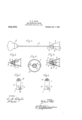
- FIG. 1 which- Figure l is a side elevation of a hat pin made in accordance with my improvement.
- Fig. 2 an end view thereof with the clutch member removed.
- Fig. 3 a sectional view at the line .aL-a: of Fig. l looking in the direction of the arrows.
- Fig. 4 a longitudinal sectional view thereof.
- Fig. 5,A a back view of the clutch or grip showing the spring attached thereto, and Fig. G, a similar view, the spring being detached.
- A represents the hat pin having a head B and a pointed end C. 'On the pointed end of the pin is placed thesafety holding device D, which is formed to represent some ilower or other suitable ornament, said.
- the safety device consisting, of the stem E provided with the conical opening F, which acts as a guide for the pin A, said conical opening terminating in the hole G, which is directly in alinement with the hole H formed in the clutch or grip l, which is provided with the lugsA or shafts J, which are journaled in thelower leaf K of the safety device.
- one side of the clutch l is formed the notch L, through which extends the coils of the spring M, which is coiled about one of theshafts d, one end of said spring adapted to rest lagainst the clutch, the other end against the lower leali K, ,so that said clutch is normally pressed inward or toward the stem Eet the safety device.
- n per end' of the clutch l is cnrvedoutrvar as indicated by'N, so that when the upper leaf 0 of the safety device, which is pivoted to the stem E, by the pin Pls 'pressed down ⁇ Ward, it will cause the upper end 'of the clutch 'l 'to move outward until it has taken a vertical position, at which time the pin A may be withdrawn from the safety device.
- the hat pin is placed in thef hat and the safety device is placed on the end of the pin, and by pushing it along said pin, said pin will first enter the conical opening F then the hole G and finally the hole H in the7 clutch l, and as. soon as the safety device is let go ot, the spring M will cause the clutch l to move out of a vertical line, thus causingthe clutch or grip l to take hold'of the pin at two points, which 'will prevent the safety device rombeing removed, until the upper leaf 0 is. pressed downward, at which time, because of the curved upper end N of the clutch or grip will cause said clutch to move to the vertical line, allowing the hat pin to be withdrawn.
- the safety device may be placed on the pin a sufficient distance for the clutch to take hold of said pin, but at said distance the point of the vpin will not protrude from said safety device, thus preventing the pin from coming in contact with a person, which would possibly injure said person.
- Another feature is, that various designs of se fety devices may he .used with a single pin, so that the user may use the device Widi diter'ent ornaments, thus varying the appearance from time to time as may be desired.
Landscapes
- Adornments (AREA)
Description
W, E. WSL?,
LOSS PEEWEN'I'IEE D EVIUE. APPLIoAToN FILED mm1, 1909.
@2,655 Patante ec. i999,
xNVENToR Mil/@0% mi? WALTER K. WOLF, OF BROWVNSTWN, PENNSYLVANA.
, Loss-rentfnnfrne nnvion.
senese.
Specification of Letters Patent.
Patenten nee. e, ieee.
Application led liarch i, 1909. Serial No. 480,822.
To all whom 'it may concern:
Be it lrnown that l, WALTER K. VVoLr, a citizen of the United States, residing at Brownstown, in the county of Lancaster and State of Pennsylvania, have invented a cer tain new and useful Improvement in Loss- Preventing Devices, of which the following is a speciiication.
My invention relates to a new and useful improvement in hat pins, and has Yfor its object to provide an exceedingly simple, and eliective device of this character, whereby `a hat pin may be provided with a safety hold.- ing device in the form of'an ornament.
A. further object of my invention is to provide a device or thecharacter described in which a safety holding device is provided for the pointed end of the pin which may be readily placed thereon or removed therefrom.
Viith these ends in View, this invention consists in the details of construction and combination of elements hereinafter set forth and then specifically designated by the claim.
ln order that those skilled in the art to which this invention apport-eins may under- .stand how to make and use the same,"l will describe its construction in detail, referring' by letter to `the accompanying drawing forming a part v of this specification, in
` which- Figure l is a side elevation of a hat pin made in accordance with my improvement. Fig. 2, an end view thereof with the clutch member removed. Fig. 3, a sectional view at the line .aL-a: of Fig. l looking in the direction of the arrows. Fig. 4, a longitudinal sectional view thereof. Fig. 5,A a back view of the clutch or grip showing the spring attached thereto, and Fig. G, a similar view, the spring being detached.
In carrying out my invention as here embodied, A represents the hat pin having a head B and a pointed end C. 'On the pointed end of the pin is placed thesafety holding device D, which is formed to represent some ilower or other suitable ornament, said.
safety device consisting, of the stem E provided with the conical opening F, which acts as a guide for the pin A, said conical opening terminating in the hole G, which is directly in alinement with the hole H formed in the clutch or grip l, which is provided with the lugsA or shafts J, which are journaled in thelower leaf K of the safety device.
ln one side of the clutch l is formed the notch L, through which extends the coils of the spring M, which is coiled about one of theshafts d, one end of said spring adapted to rest lagainst the clutch, the other end against the lower leali K, ,so that said clutch is normally pressed inward or toward the stem Eet the safety device. The n per end' of the clutch l is cnrvedoutrvar as indicated by'N, so that when the upper leaf 0 of the safety device, which is pivoted to the stem E, by the pin Pls 'pressed down\ Ward, it will cause the upper end 'of the clutch 'l 'to move outward until it has taken a vertical position, at which time the pin A may be withdrawn from the safety device.
In practice the hat pin is placed in thef hat and the safety device is placed on the end of the pin, and by pushing it along said pin, said pin will first enter the conical opening F then the hole G and finally the hole H in the7 clutch l, and as. soon as the safety device is let go ot, the spring M will cause the clutch l to move out of a vertical line, thus causingthe clutch or grip l to take hold'of the pin at two points, which 'will prevent the safety device rombeing removed, until the upper leaf 0 is. pressed downward, at which time, because of the curved upper end N of the clutch or grip will cause said clutch to move to the vertical line, allowing the hat pin to be withdrawn.
One of the important features of my invention is that the safety device may be placed on the pin a suficient distance for the clutch to take hold of said pin, but at said distance the point of the vpin will not protrude from said safety device, thus preventing the pin from coming in contact with a person, which would possibly injure said person. Another feature is, that various designs of se fety devices may he .used with a single pin, so that the user may use the device Widi diter'ent ornaments, thus varying the appearance from time to time as may be desired.
t course l 4do not wish to he limited to the exact details of construction here shown,
g v 942,695 v as these may be varied within -the scope of'. 'leaf by neahs of the shafts,v 'and a spring the appended claim without departing fromA coiled about one of said shafts, one end of 15 ,l L ll'i'ffspl rit of my invention. n "which rests against the clutch member, the
' l avin-g thus. fully described my mvenopposite end against the lower leaf., sub- 5 "tion, what I claim as new and useful, is l l stantially, as shown and described.
As an article of manufacture, a safety'ldea In testimony whereof, I have hereunto vice consisting of a stem having a conical aliixed my signature in the presence of two 20 opening termnaing in a;1 hole formed theresubscribing Witnesses. in a lower ea secure to said stem an 4 f 10 upper leaf pivoted to said stem, a cliith WLIER K WOLF member provided with shafts and having a -Witnesses:
hole and a notch formed therein, said clutch JAMES COHEN, Y member adapted to be journaled in the lower CHAS. F. STAUFFER.
Priority Applications (1)
| Application Number | Priority Date | Filing Date | Title |
|---|---|---|---|
| US48062208A US942695A (en) | 1908-03-01 | 1908-03-01 | Loss-preventing device. |
Applications Claiming Priority (1)
| Application Number | Priority Date | Filing Date | Title |
|---|---|---|---|
| US48062208A US942695A (en) | 1908-03-01 | 1908-03-01 | Loss-preventing device. |
Publications (1)
| Publication Number | Publication Date |
|---|---|
| US942695A true US942695A (en) | 1909-12-07 |
Family
ID=3011117
Family Applications (1)
| Application Number | Title | Priority Date | Filing Date |
|---|---|---|---|
| US48062208A Expired - Lifetime US942695A (en) | 1908-03-01 | 1908-03-01 | Loss-preventing device. |
Country Status (1)
| Country | Link |
|---|---|
| US (1) | US942695A (en) |
-
1908
- 1908-03-01 US US48062208A patent/US942695A/en not_active Expired - Lifetime
Similar Documents
| Publication | Publication Date | Title |
|---|---|---|
| US979342A (en) | Collar-fastener. | |
| US992659A (en) | Brooch-fastener. | |
| US355980A (en) | Clevis | |
| US995744A (en) | Hat-pin protector. | |
| US1007081A (en) | Safety stick-pin. | |
| US1053840A (en) | Hat-pin. | |
| US997451A (en) | Safety hat-pin. | |
| US1539551A (en) | Hook | |
| US719919A (en) | Safety-catch for brooches, &c. | |
| US765757A (en) | Safety-pin. | |
| US778512A (en) | Pin. | |
| US1005073A (en) | Scarf-pin. | |
| US1162176A (en) | Flower-holder. | |
| US1213903A (en) | Hat-pin. | |
| US871009A (en) | Collar stud, button, or the like. | |
| US1049806A (en) | Hat-pin-point protector. | |
| US1078683A (en) | Hat-pin guard. | |
| US1020131A (en) | Hat-pin holder and sheath. | |
| US497065A (en) | Pencil-holder | |
| US1055130A (en) | Safety device for pins. | |
| US589145A (en) | Lydia ann scott | |
| US931822A (en) | Separable stud. | |
| US1081231A (en) | Shoe and glove fastener. | |
| US311048A (en) | Sleeve or collar button | |
| US914150A (en) | Safety-catch for stick-pins and similar articles of jewelry. |