US935021A - Window-refrigerator. - Google Patents
Window-refrigerator. Download PDFInfo
- Publication number
- US935021A US935021A US46360908A US1908463609A US935021A US 935021 A US935021 A US 935021A US 46360908 A US46360908 A US 46360908A US 1908463609 A US1908463609 A US 1908463609A US 935021 A US935021 A US 935021A
- Authority
- US
- United States
- Prior art keywords
- box
- window
- slides
- refrigerator
- casing
- Prior art date
- Legal status (The legal status is an assumption and is not a legal conclusion. Google has not performed a legal analysis and makes no representation as to the accuracy of the status listed.)
- Expired - Lifetime
Links
- 238000010276 construction Methods 0.000 description 3
- 241001289435 Astragalus brachycalyx Species 0.000 description 1
- 235000002917 Fraxinus ornus Nutrition 0.000 description 1
- 241001080526 Vertica Species 0.000 description 1
- 230000000694 effects Effects 0.000 description 1
- 210000003811 finger Anatomy 0.000 description 1
- 239000002184 metal Substances 0.000 description 1
- 238000012856 packing Methods 0.000 description 1
- 238000005057 refrigeration Methods 0.000 description 1
- 230000000284 resting effect Effects 0.000 description 1
- 210000003813 thumb Anatomy 0.000 description 1
Images
Classifications
-
- A—HUMAN NECESSITIES
- A47—FURNITURE; DOMESTIC ARTICLES OR APPLIANCES; COFFEE MILLS; SPICE MILLS; SUCTION CLEANERS IN GENERAL
- A47B—TABLES; DESKS; OFFICE FURNITURE; CABINETS; DRAWERS; GENERAL DETAILS OF FURNITURE
- A47B71/00—Cabinets for perishable goods, e.g. meat safes, fly-proof cabinets
Definitions
- This invention relates to im rovements in that class of refrigerators w,- ich are used in windows, and which utilize the low atmospheric temperatures offall, winter and spring months for refri eration for household and other uses, wit out the aid of ice or other artificial refrigerating agents.
- a window refrigerator readily capable of application to windows of different widths without permitting the ingress of coldair resulting from variations in the width of the refrigerator box and window casing
- a window refrigerator which may be easily and snugly fitted between the :raised sash and. the w1ndow casing, without requiring any external supportin means for the rear or outer end of the re rigerator box, and to provide a window refrigerator which may be easily and quickly adjusted so as to extend to a greater or less extent outside the window
- the invention consists in a window refrigerator having the novel features of construction" and mode of use substantially as hereinafter described and more particularly pointed out in the claims.
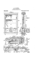
- Figure .1 is a front elevational view from the inner side of a window equipped with my improved refrigerator.
- Fig. 2 is a vertica'l transverse section through Fig. ,1, showing the refrigerator partly in side elevation and partly in verticalseotion.
- Fig. 3 is a perspective elevation of the refrigerator.
- Fig. 4 is a vertical section, somewhat enlarged, through the top wall of the refrigerator box, in the .plane of the transversely mounted slides which support the filling strips that close the openings between the sides of the refrigerator box and the adja- 1 .cent sides of the window casing.
- Fig. 5 is a detail sectional View, further enlarged, on the line 55 of Fig. 4.
- Fig. 6 is a perspec- .tive detail of one of the jolnt strips that is applied ta the side of the refrigerator box for the pur ose of making a substantially air-tight joint between the latter and the fillin strip or strips of the closure.
- 10 designates the casing, and 11 and 12 the lower" and .upper sashes, respectively, of an ordinary Window.
- FIG. 13 designates as an entirety the refrigerator case, herein shown as consisting of a [plain rectangular box having a closed outer end and 0 en inner end provided with an Ordinary hinged .door 14 that is preferably arranged to open downwardly.
- Therefrigerator box is adapted to rest on the sill of the window casing and to be engagedon its upper side by the lower bar of the lower sash 11.
- I provide the latter with longitudinally adjustable Wings which are designed to effect a snug and substantially air-tight closure for the opening or openings that would otherwise be present between one or both sides of the box and the adjacent side or sides of the window casing.
- these laterally extending wings In order to make these laterally extending wings readily extensible and cont-ractible so as to be adjustable to openings 16 and 17 designate a pair of slides that and bottom .walls of the box 13.
- a pair .of such slides is mounted on each 'side of the'box in longitudinal alinement with each other.
- the upper slide 16 is slotted inwardly for the greater part of its length, while the upper face of the lower slide 17 is similarly grooved or channeled.
- the slides 16 and L7 operate in suitably bent sheet metal slideways -18.and 19, respectively, secured to the top .and bottom walls of the box; and in order ,to secure .the upper slide 16 in any adjusted position, a bolt 20 passes through a hoe in the slideway 18 and a registering hole in the top of the box, said-boltengaging of varying widths, I preferably construct them'as follows.
- the outermost of these strips engages the sash guide-groove of the window casing, while the innermost engages the side wall of the box, to which latter is preferably secured a grooved joint strip, such as- '23 (Fig. 6).
- the slides and slideways as described may be permanently mounted on the top and bottom walls of the box, if desired; but, in orderto provide for the adjustment of the box so that the same will extend to a greateror less extent outside the window, I- make the slideways 18- and 19 and the joint strips 23 readily detachable and adjustable: To this end I form in vthe outer sides of the top,
- the lower sash is raised and the box laid on the sill thereof, the slides and slideways having been previously fitted to one of the several grooves 24, 25 and 26, according to the amount of refrigeration desired, the slides 16 and 17 are then extended until their ends engage the bottoms of the sash guiding grooves of the window casing, and the filllng strips 22 are'then inserted through the slotted slides 16, resting at their lower ends in the grooves .of the slides 17.
- the filling strips 22 By making the filling strips 22 in a variety of widths, practically any width of closure required is'readily obtainable.
- the sash is then lowered until its lower edge engages the top of the slideway 18; and to insure an air-tight joint,
- I may provide slots 32 in the front sides of the slideways, through which any pointed tool may be inserted to engage holes 33 formed in the adjacent edges of the slide, so that by a side thrust the outer end of the slide is easily projected sufliciently to enable it to be grasped by the thumb and finger of the operator and withdrawn the rest of the way as far as necessary.
- the regulation of the temperature is secured chiefly by the means described for adjusting the extent to which the box projects out of the window. If desired, however, I may also employ a combined ventilating and temperature-regulating device,
- the door 14 may also be provided with a ventilator similar to that applied to the outer wall of the box, as
- the door is provided on its upper edge with an ordinary spring-actuated latch 40 cotiperating with a keeper 41 on the upper my invention provides a convenient and inexpensive refrlgerator of the class described which is capable of application to windows of considerably varying widths,
- the box is preferably equipped, as shown, with one of the extensible and contractible wings forming a closure on each, side thereof, but, of course, this may be employed on one; side only, if desired, without involving any departure from the spirit or principle of the invention.
- the invention may also be modified as to its details of construction in other respects without involving any departure therefrom or sacrificing any of the enefits and advantages secured thereby. Hence, I do not limit ⁇ the invention to the particular construction disclosed, except to the extent clearly indicated in specific claims.
- a Window refrigerator the combination with a box adapted to reston the sill of a window-casing and having fixed" side walls, of a laterally extending wing on a side wall of said box adapted to close the window-opening between said side wall of the box and the adjacent side ofthe window casing, substantially as described.
- a window refrigerator the combination with a box adapted to rest on the sill of a window-casing, of a laterally extending wing on said box adapted to close the window-opening between a side of the box and the adjacent side of the window-casing, said wing being adjustable to variations in the distance between said box and windowcasing, substantially as described.
- a window refrigerator the combination with abox adapted to rest on the sill of a window-casing, of a pair of slides mounted on and transversely of the top and bottom walls of said box, and a plurality of filling-strips between and held 'by the projecting portions of said slides and umtedly constituting a closure for the opening between a side of the box and the adj acent side of the window casing, substantially as described.
- a window refrigerator In a Window refrigerator, thecombination with a box adaptedto rest on the sill of a window-casing, of a pair of slides 7.
- a window refrigerator In a window refrigerator, the combination with a box adapted to rest on the Slll of a window-casing, of slidesways secured slides mounted in said slideways, and a plurality of filling-strips removably engaging the projecting portions of said slides and unitedly constituting a closure for the opening between a side of said box and the adjacent side of the window-casing, substantially as described.
- a window refrigerator the combination with a box adapted to rest on the sill of a window-casing, of a pair of slides mounted on and transversely of the top and bottom walls of said box, a joint-str1p secured to the side 01 said box between said slides, and a plurality of filling-strips mounted at their upper and lower ends in said slides between the side of the box and the adjacent sash-guiding groove of the window-casing, said filling-strips having tongue-and-groove joints with each other and with said joint-strip, substantially as described.
- a window refrigerator the combination with a box adapted to rest on the sill -of a window-casing and provided with a plurality of grooves disposed at intervals transversely of its top and bottom walls, of
- a window refrigerator the combination with a box adapted to rest on the sill of a window-casing and provided with a plurality of grooves disposed at intervals between the front and rear ends of said box to the top and bottom walls of said box transversely thereof, longitudinally grooved 4 w e I 035,021-
Landscapes
- Physics & Mathematics (AREA)
- Thermal Sciences (AREA)
- Refrigerator Housings (AREA)
Description
G. G. HATGHER. WINDOW REFRIGERATOR.
APPLIOATION FILED NOV. 20, 1908.
935,021, v Patented Sept.28, 1909.
Twin 4 37 I I I 5% 1% I 35 I 25 J6 UNITED STATES PATENT orrion.
CHARLES C. HATCHER, OF CHICAGO, ILLINOIS.
WINDOW-BEZFBIGERATQR.
Specification of Letters Patent.
Patented Sept. 28, 1909*.
Application filed November :20, 1908. Serial No. 463,609.-
of which the following is a specification.
This invention relates to im rovements in that class of refrigerators w,- ich are used in windows, and which utilize the low atmospheric temperatures offall, winter and spring months for refri eration for household and other uses, wit out the aid of ice or other artificial refrigerating agents.
Among the chief objects sought by the invention are, to providea window refrigerator readily capable of application to windows of different widths without permitting the ingress of coldair resulting from variations in the width of the refrigerator box and window casing, to provide a window refrigerator which may be easily and snugly fitted between the :raised sash and. the w1ndow casing, without requiring any external supportin means for the rear or outer end of the re rigerator box, and to provide a window refrigerator which may be easily and quickly adjusted so as to extend to a greater or less extent outside the window,
according to the temperature that may prevall outslde at any given time.
To these and other minor ends, the invention consists in a window refrigerator having the novel features of construction" and mode of use substantially as hereinafter described and more particularly pointed out in the claims.
My invention will be readily understood when considered in connection with the accompanying drawing which shows'one practical mechanical embodiment thereof, and .in which,--
Figure .1 is a front elevational view from the inner side of a window equipped with my improved refrigerator. Fig. 2 is a vertica'l transverse section through Fig. ,1, showing the refrigerator partly in side elevation and partly in verticalseotion. Fig. 3 is a perspective elevation of the refrigerator.
Fig. 4 is a vertical section, somewhat enlarged, through the top wall of the refrigerator box, in the .plane of the transversely mounted slides which support the filling strips that close the openings between the sides of the refrigerator box and the adja- 1 .cent sides of the window casing. Fig. 5 is a detail sectional View, further enlarged, on the line 55 of Fig. 4. Fig. 6 is a perspec- .tive detail of one of the jolnt strips that is applied ta the side of the refrigerator box for the pur ose of making a substantially air-tight joint between the latter and the fillin strip or strips of the closure.
Re erring to the drawing, 10 designates the casing, and 11 and 12 the lower" and .upper sashes, respectively, of an ordinary Window.
13 designates as an entirety the refrigerator case, herein shown as consisting of a [plain rectangular box having a closed outer end and 0 en inner end provided with an Ordinary hinged .door 14 that is preferably arranged to open downwardly.
At 15 I have indicated a removable table or shelf that may be employed in the refrigerator box or omitted, as desired.
Therefrigerator box is adapted to rest on the sill of the window casing and to be engagedon its upper side by the lower bar of the lower sash 11. To adapt the box to window .openings of widths more or less ex- .ceeding the width of .the box, I provide the latter with longitudinally adjustable Wings which are designed to effect a snug and substantially air-tight closure for the opening or openings that would otherwise be present between one or both sides of the box and the adjacent side or sides of the window casing. In order to make these laterally extending wings readily extensible and cont-ractible so as to be adjustable to openings 16 and 17 designate a pair of slides that and bottom .walls of the box 13. Preferably, and. as shown, a pair .of such slides is mounted on each 'side of the'box in longitudinal alinement with each other. The upper slide 16 is slotted inwardly for the greater part of its length, while the upper face of the lower slide 17 is similarly grooved or channeled. The slides 16 and L7 operate in suitably bent sheet metal slideways -18.and 19, respectively, secured to the top .and bottom walls of the box; and in order ,to secure .the upper slide 16 in any adjusted position, a bolt 20 passes through a hoe in the slideway 18 and a registering hole in the top of the box, said-boltengaging of varying widths, I preferably construct them'as follows.
the slides and preferably form lateral tongue and groove joints with each other. The outermost of these strips engages the sash guide-groove of the window casing, while the innermost engages the side wall of the box, to which latter is preferably secured a grooved joint strip, such as- '23 (Fig. 6). The slides and slideways as described may be permanently mounted on the top and bottom walls of the box, if desired; but, in orderto provide for the adjustment of the box so that the same will extend to a greateror less extent outside the window, I- make the slideways 18- and 19 and the joint strips 23 readily detachable and adjustable: To this end I form in vthe outer sides of the top,
bottom and side walls of the box in various vertical transverse planes thereof grooves or channels 24,125 and 26 extending entirely around the box, the horizontal portions of said grooves accommodating the slideways and slides in the manner clearly shown in Figs. 3 and 5, while the vertical portions of said grooves accommodate the joint strips 23. vThe latterare conveniently secured in place by forming therewith inwardly turned horizontal arms 27 and 28 that lie in the countersunk end portions of the horizontal members ofthe box grooves, as shown in Fig. 4, and are suitably apertured as at 29 and 30; The aperture 29 in the upper arm of the joint-strip is engaged by the bolt 20, while the aperture 30 in the lower arm is engaged by a screw 20 passed through'the bottom wall of the box, the lower end of the screw projecting into the channel or groove of the lower slide 17.
0 fit the box to a window, the lower sash is raised and the box laid on the sill thereof, the slides and slideways having been previously fitted to one of the several grooves 24, 25 and 26, according to the amount of refrigeration desired, the slides 16 and 17 are then extended until their ends engage the bottoms of the sash guiding grooves of the window casing, and the filllng strips 22 are'then inserted through the slotted slides 16, resting at their lower ends in the grooves .of the slides 17. By making the filling strips 22 in a variety of widths, practically any width of closure required is'readily obtainable. The sash is then lowered until its lower edge engages the top of the slideway 18; and to insure an air-tight joint,
inner edge of the. b x. Y From the foregoing it will be seen that a felt or similar packing strip 31 .is applied to the top of the slideway 18 and the projecting portions of the strips 16.
It will be observed that by reason ofithe engagement of the ends of the-slides 16 and 17 with the sash guide grooves of the win- .dow casing, the box is supported in h0ri-.-
zontal position without the necessity of employing any external supports for the outer end of the box.
To facilitate the withdrawal of the slides from the slideways when the former are completely telescoped, into the latter, I may provide slots 32 in the front sides of the slideways, through which any pointed tool may be inserted to engage holes 33 formed in the adjacent edges of the slide, so that by a side thrust the outer end of the slide is easily projected sufliciently to enable it to be grasped by the thumb and finger of the operator and withdrawn the rest of the way as far as necessary.
The regulation of the temperature is secured chiefly by the means described for adjusting the extent to which the box projects out of the window. If desired, however, I may also employ a combined ventilating and temperature-regulating device,
preferably located in the outer vertical Wall of the box, consisting of an o ening 34 formed in the latter and a manna 1y operable slide 35 mounted in-slideways 36 whereby said opening may be wholly closed or wholly or partially opened, as'desired. In
very cold weather it may also be desirable to moderate the temperature existing in the refrigerator by the admission of more or less relatively warm air from the inside of the room; and for this purpose the door 14 may also be provided with a ventilator similar to that applied to the outer wall of the box, as
represented by the slide 37 mounted in slide- Ways 38 on the door 14 and controlling a slot 39 formed in the latter.
The door is provided on its upper edge with an ordinary spring-actuated latch 40 cotiperating with a keeper 41 on the upper my invention provides a convenient and inexpensive refrlgerator of the class described which is capable of application to windows of considerably varying widths,
while affording a completeclosure for such parts of the opening necessitated thereby as are ,notoccupied by the box itself. The box is preferably equipped, as shown, with one of the extensible and contractible wings forming a closure on each, side thereof, but, of course, this may be employed on one; side only, if desired, without involving any departure from the spirit or principle of the invention. The invention may also be modified as to its details of construction in other respects without involving any departure therefrom or sacrificing any of the enefits and advantages secured thereby. Hence, I do not limit\ the invention to the particular construction disclosed, except to the extent clearly indicated in specific claims.
I claim:
1. In a Window refrigerator, the combination with a box adapted to reston the sill of a window-casing and having fixed" side walls, of a laterally extending wing on a side wall of said box adapted to close the window-opening between said side wall of the box and the adjacent side ofthe window casing, substantially as described.
2. In a window refrigerator, the combination with a box adapted to rest on the sill of a window-casing, of a laterally extending wing on said box adapted to close the window-opening between a side of the box and the adjacent side of the window-casing, said wing being adjustable to variations in the distance between said box and windowcasing, substantially as described.
, 3. In a window refrigerator, the combination with a box adapted to rest on the sill of a window-casing, of a pair of laterally extending Wings on the respective sides of said box adapted to close the openings 'between the sides of said box and the adjacent the sides of'the box and the adjacent sides of the window-easing, substant ally as described. c
5. In a window refrigerator, the combination with abox adapted to rest on the sill of a window-casing, of a pair of slides mounted on and transversely of the top and bottom walls of said box, and a plurality of filling-strips between and held 'by the projecting portions of said slides and umtedly constituting a closure for the opening between a side of the box and the adj acent side of the window casing, substantially as described. v
6. In a Window refrigerator, thecombination with a box adaptedto rest on the sill of a window-casing, of a pair of slides 7. In a window refrigerator, the combination with a box adapted to rest on the Slll of a window-casing, of slidesways secured slides mounted in said slideways, and a plurality of filling-strips removably engaging the projecting portions of said slides and unitedly constituting a closure for the opening between a side of said box and the adjacent side of the window-casing, substantially as described.
.8. In a window refrigerator, the combination with a box adapted to rest on the sill of a window-casing, of a pair of slides mounted on and transversely of the top and bottom walls of said box, a joint-str1p secured to the side 01 said box between said slides, and a plurality of filling-strips mounted at their upper and lower ends in said slides between the side of the box and the adjacent sash-guiding groove of the window-casing, said filling-strips having tongue-and-groove joints with each other and with said joint-strip, substantially as described.
9. In a window refrigerator, the combination with a box adapted to rest on the sill of awindow-casing, of a air eof slides, meansfor detachably mountlngsaid slides on and transversely of the top and bottom walls of the box at any of a plurality of different points between the front and rear of the=box, and a closure mounted in the projecting portions of said slides, substantially as described.
10. In a window refrigerator, the combination with a box adapted to rest on the sill -of a window-casing and provided with a plurality of grooves disposed at intervals transversely of its top and bottom walls, of
transversely of its top and bottom walls, of
upper and lower slideways removably mounted in vertically alined pairs, of'
grooves, slides in said sliideways, means for detachably securing said slides and slide ways in-said grooves, and a closure mounted in the projecting portionsof said slides, substantially as described. 7
12. In a window refrigerator, the combination with a box adapted to rest on the sill of a window-casing and provided with a plurality of grooves disposed at intervals between the front and rear ends of said box to the top and bottom walls of said box transversely thereof, longitudinally grooved 4 w e I 035,021-
and extending entirely therearound, of upper and lower 'slideways, slides mounted 1n said joint-strips and the adjacent sash guide saidv slidewaysvertically disposed jointgrooves, substantially as described. I strips, means for detachably securing said 7 CHARLES C. HATCHER. 1E slideways, slides and joint-strips inter- Witnesses? changeably in any of said grooves, and a SAMUEL N. POND, plurality vof filling strips mounted in the FREDERICK G. GOODWIN.
projecting portions of said slides between
Priority Applications (1)
| Application Number | Priority Date | Filing Date | Title |
|---|---|---|---|
| US46360908A US935021A (en) | 1908-11-20 | 1908-11-20 | Window-refrigerator. |
Applications Claiming Priority (1)
| Application Number | Priority Date | Filing Date | Title |
|---|---|---|---|
| US46360908A US935021A (en) | 1908-11-20 | 1908-11-20 | Window-refrigerator. |
Publications (1)
| Publication Number | Publication Date |
|---|---|
| US935021A true US935021A (en) | 1909-09-28 |
Family
ID=3003444
Family Applications (1)
| Application Number | Title | Priority Date | Filing Date |
|---|---|---|---|
| US46360908A Expired - Lifetime US935021A (en) | 1908-11-20 | 1908-11-20 | Window-refrigerator. |
Country Status (1)
| Country | Link |
|---|---|
| US (1) | US935021A (en) |
Cited By (3)
| Publication number | Priority date | Publication date | Assignee | Title |
|---|---|---|---|---|
| US2433104A (en) * | 1944-06-24 | 1947-12-23 | Westinghouse Electric Corp | Air-conditioning apparatus |
| US2814244A (en) * | 1954-05-26 | 1957-11-26 | Paul E Hord | Window mounted room air conditioner |
| US2929373A (en) * | 1958-02-14 | 1960-03-22 | Berns Air King Corp | Portable fan-exhausted cooking device |
-
1908
- 1908-11-20 US US46360908A patent/US935021A/en not_active Expired - Lifetime
Cited By (3)
| Publication number | Priority date | Publication date | Assignee | Title |
|---|---|---|---|---|
| US2433104A (en) * | 1944-06-24 | 1947-12-23 | Westinghouse Electric Corp | Air-conditioning apparatus |
| US2814244A (en) * | 1954-05-26 | 1957-11-26 | Paul E Hord | Window mounted room air conditioner |
| US2929373A (en) * | 1958-02-14 | 1960-03-22 | Berns Air King Corp | Portable fan-exhausted cooking device |
Similar Documents
| Publication | Publication Date | Title |
|---|---|---|
| US2895182A (en) | Window structure | |
| US2649629A (en) | Louver construction | |
| US2854072A (en) | Plastic wicket for screens | |
| US2580621A (en) | Window shutter | |
| US953803A (en) | Window provision-receptacle. | |
| US2324423A (en) | Window shade mounting | |
| US791818A (en) | Provision-safe. | |
| US2579099A (en) | Window construction | |
| US1917721A (en) | Provision cabinet | |
| US1407447A (en) | Window-cooling box | |
| US1732870A (en) | Ventilator | |
| US956527A (en) | Pivoted sliding window. | |
| US1203380A (en) | Window-refrigerator. | |
| US3440768A (en) | Dual sash window unit | |
| US2383852A (en) | Window construction | |
| US2646599A (en) | Window structure | |
| US1696130A (en) | Window constbuction | |
| US1703479A (en) | Reenforced metal window sash | |
| US1992782A (en) | Window ventilator | |
| US666845A (en) | Window-ventilator. | |
| US604799A (en) | Window-screen | |
| US1758885A (en) | Window frame | |
| US1952438A (en) | Sash window | |
| US1399787A (en) | Window-ventilator | |
| US589453A (en) | Window and casing for gars |