US9308564B2 - Hot stamping system and method - Google Patents
Hot stamping system and method Download PDFInfo
- Publication number
- US9308564B2 US9308564B2 US14/069,441 US201314069441A US9308564B2 US 9308564 B2 US9308564 B2 US 9308564B2 US 201314069441 A US201314069441 A US 201314069441A US 9308564 B2 US9308564 B2 US 9308564B2
- Authority
- US
- United States
- Prior art keywords
- blanks
- chambers
- furnace
- hot forming
- forming apparatus
- Prior art date
- Legal status (The legal status is an assumption and is not a legal conclusion. Google has not performed a legal analysis and makes no representation as to the accuracy of the status listed.)
- Active, expires
Links
Images
Classifications
-
- B—PERFORMING OPERATIONS; TRANSPORTING
- B21—MECHANICAL METAL-WORKING WITHOUT ESSENTIALLY REMOVING MATERIAL; PUNCHING METAL
- B21D—WORKING OR PROCESSING OF SHEET METAL OR METAL TUBES, RODS OR PROFILES WITHOUT ESSENTIALLY REMOVING MATERIAL; PUNCHING METAL
- B21D22/00—Shaping without cutting, by stamping, spinning, or deep-drawing
- B21D22/02—Stamping using rigid devices or tools
- B21D22/022—Stamping using rigid devices or tools by heating the blank or stamping associated with heat treatment
-
- B—PERFORMING OPERATIONS; TRANSPORTING
- B21—MECHANICAL METAL-WORKING WITHOUT ESSENTIALLY REMOVING MATERIAL; PUNCHING METAL
- B21D—WORKING OR PROCESSING OF SHEET METAL OR METAL TUBES, RODS OR PROFILES WITHOUT ESSENTIALLY REMOVING MATERIAL; PUNCHING METAL
- B21D35/00—Combined processes according to or processes combined with methods covered by groups B21D1/00 - B21D31/00
-
- B—PERFORMING OPERATIONS; TRANSPORTING
- B21—MECHANICAL METAL-WORKING WITHOUT ESSENTIALLY REMOVING MATERIAL; PUNCHING METAL
- B21D—WORKING OR PROCESSING OF SHEET METAL OR METAL TUBES, RODS OR PROFILES WITHOUT ESSENTIALLY REMOVING MATERIAL; PUNCHING METAL
- B21D37/00—Tools as parts of machines covered by this subclass
- B21D37/16—Heating or cooling
-
- B—PERFORMING OPERATIONS; TRANSPORTING
- B21—MECHANICAL METAL-WORKING WITHOUT ESSENTIALLY REMOVING MATERIAL; PUNCHING METAL
- B21D—WORKING OR PROCESSING OF SHEET METAL OR METAL TUBES, RODS OR PROFILES WITHOUT ESSENTIALLY REMOVING MATERIAL; PUNCHING METAL
- B21D43/00—Feeding, positioning or storing devices combined with, or arranged in, or specially adapted for use in connection with, apparatus for working or processing sheet metal, metal tubes or metal profiles; Associations therewith of cutting devices
- B21D43/02—Advancing work in relation to the stroke of the die or tool
- B21D43/04—Advancing work in relation to the stroke of the die or tool by means in mechanical engagement with the work
- B21D43/08—Advancing work in relation to the stroke of the die or tool by means in mechanical engagement with the work by rollers
-
- B—PERFORMING OPERATIONS; TRANSPORTING
- B21—MECHANICAL METAL-WORKING WITHOUT ESSENTIALLY REMOVING MATERIAL; PUNCHING METAL
- B21D—WORKING OR PROCESSING OF SHEET METAL OR METAL TUBES, RODS OR PROFILES WITHOUT ESSENTIALLY REMOVING MATERIAL; PUNCHING METAL
- B21D53/00—Making other particular articles
- B21D53/88—Making other particular articles other parts for vehicles, e.g. cowlings, mudguards
-
- C—CHEMISTRY; METALLURGY
- C21—METALLURGY OF IRON
- C21D—MODIFYING THE PHYSICAL STRUCTURE OF FERROUS METALS; GENERAL DEVICES FOR HEAT TREATMENT OF FERROUS OR NON-FERROUS METALS OR ALLOYS; MAKING METAL MALLEABLE, e.g. BY DECARBURISATION OR TEMPERING
- C21D9/00—Heat treatment, e.g. annealing, hardening, quenching or tempering, adapted for particular articles; Furnaces therefor
- C21D9/005—Furnaces in which the charge is moving up or down
-
- F—MECHANICAL ENGINEERING; LIGHTING; HEATING; WEAPONS; BLASTING
- F27—FURNACES; KILNS; OVENS; RETORTS
- F27B—FURNACES, KILNS, OVENS, OR RETORTS IN GENERAL; OPEN SINTERING OR LIKE APPARATUS
- F27B9/00—Furnaces through which the charge is moved mechanically, e.g. of tunnel type; Similar furnaces in which the charge moves by gravity
- F27B9/02—Furnaces through which the charge is moved mechanically, e.g. of tunnel type; Similar furnaces in which the charge moves by gravity of multiple-track type; of multiple-chamber type; Combinations of furnaces
- F27B9/021—Furnaces through which the charge is moved mechanically, e.g. of tunnel type; Similar furnaces in which the charge moves by gravity of multiple-track type; of multiple-chamber type; Combinations of furnaces having two or more parallel tracks
- F27B9/022—With two tracks moving in opposite directions
- F27B9/023—With two tracks moving in opposite directions with a U turn at one end
- F27B9/024—With two tracks moving in opposite directions with a U turn at one end with superimposed tracks
-
- F—MECHANICAL ENGINEERING; LIGHTING; HEATING; WEAPONS; BLASTING
- F27—FURNACES; KILNS; OVENS; RETORTS
- F27B—FURNACES, KILNS, OVENS, OR RETORTS IN GENERAL; OPEN SINTERING OR LIKE APPARATUS
- F27B9/00—Furnaces through which the charge is moved mechanically, e.g. of tunnel type; Similar furnaces in which the charge moves by gravity
- F27B9/14—Furnaces through which the charge is moved mechanically, e.g. of tunnel type; Similar furnaces in which the charge moves by gravity characterised by the path of the charge during treatment; characterised by the means by which the charge is moved during treatment
- F27B9/20—Furnaces through which the charge is moved mechanically, e.g. of tunnel type; Similar furnaces in which the charge moves by gravity characterised by the path of the charge during treatment; characterised by the means by which the charge is moved during treatment the charge moving in a substantially straight path tunnel furnace
- F27B9/24—Furnaces through which the charge is moved mechanically, e.g. of tunnel type; Similar furnaces in which the charge moves by gravity characterised by the path of the charge during treatment; characterised by the means by which the charge is moved during treatment the charge moving in a substantially straight path tunnel furnace being carried by a conveyor
- F27B9/2407—Furnaces through which the charge is moved mechanically, e.g. of tunnel type; Similar furnaces in which the charge moves by gravity characterised by the path of the charge during treatment; characterised by the means by which the charge is moved during treatment the charge moving in a substantially straight path tunnel furnace being carried by a conveyor the conveyor being constituted by rollers (roller hearth furnace)
-
- C—CHEMISTRY; METALLURGY
- C21—METALLURGY OF IRON
- C21D—MODIFYING THE PHYSICAL STRUCTURE OF FERROUS METALS; GENERAL DEVICES FOR HEAT TREATMENT OF FERROUS OR NON-FERROUS METALS OR ALLOYS; MAKING METAL MALLEABLE, e.g. BY DECARBURISATION OR TEMPERING
- C21D1/00—General methods or devices for heat treatment, e.g. annealing, hardening, quenching or tempering
- C21D1/62—Quenching devices
- C21D1/673—Quenching devices for die quenching
Definitions
- the inventions relates generally to a system and method for hot forming a plurality of parts, such as steel parts for chassis and automotive body applications.
- Hot forming processes typically comprise heating a steel blank in a furnace, followed by stamping the heated blank between a pair of dies to form a shaped part, and quenching the shaped part between the dies.
- the steel blank is typically heated in the furnace to achieve an austenitic microstructure, and then quenched in the dies to transform the austenitic microstructure to a martensitic microstructure.
- the hot forming process preferably runs continuously to produce a plurality of the shaped parts at a high rate and low cost. However, when the furnace malfunctions, the entire system must be shut down for a period of time while the furnace is repaired, which increases the cost per part produced by the system.
- the invention provides a system for hot forming a plurality of parts, such as steel parts for use as chassis or body components of an automobile.
- the system comprises a furnace including a plurality of shelves stacked vertically relative to one another. Each shelf includes a plurality of driven rollers for conveying a plurality of blanks through the furnace.
- the furnace also includes a plurality of heaters for heating the blanks, wherein each heater is disposed adjacent one of the shelves. Each shelf and the adjacent heater is removable from the furnace, for example when the heater is malfunctioning.
- the system further includes a hot forming apparatus for shaping the heated blanks, and a blank feeder for conveying the heated blanks from the shelves of the furnace to the hot forming apparatus.
- the invention also provides a method for hot forming a plurality of parts.
- the method includes conveying a plurality of blanks along a plurality of shelves of a furnace, and heating the plurality of blanks using a heater disposed adjacent each shelf.
- the method also includes removing the heater and the adjacent shelf from the furnace when the heater is malfunctioning while continuing to heat the blanks on the other shelves.
- the method further includes conveying the heated blanks from the furnace to a hot forming apparatus, and shaping the heated blanks in the hot forming apparatus.
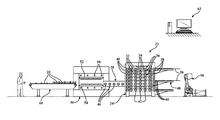
- FIG. 1 is a side view of an exemplary hot forming system for producing a plurality of shaped parts
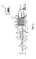
- FIG. 2 is an exemplary die of a hot forming apparatus used in the system of FIG. 1 .
- FIG. 1 an exemplary system 22 for hot forming a plurality of shaped parts 20 is generally shown in FIG. 1 .
- the system 22 includes a furnace 24 for heating a plurality of blanks 26 , a hot forming apparatus 30 for shaping the heated blanks 26 , and a blank feeder 28 for conveying the heated blanks 26 from the furnace 24 to the hot forming apparatus 30 .
- the system 22 provides reduced down time and thus reduced overhead costs per part 20 , compared to other hot forming systems.
- the system 22 also requires less floor space compared to the other systems.
- the blanks 26 used to manufacture the shaped parts 20 are typically formed of metal, but can be formed of other materials.
- the blanks 26 are formed of steel material, such pure steel or a steel alloy.
- the shaped parts 20 are typically designed for use as chassis or automotive body components, the parts 20 can alternatively be used in other applications.
- the system 22 includes the furnace 24 for heating a plurality of the blanks 26 prior to shaping the blanks 26 in the hot forming apparatus 30 .
- the furnace 24 includes a plurality of shelves 32 stacked vertically relative to one another and a heater 34 disposed adjacent each shelf 32 .
- Each heater 34 can comprise a single heating element or a plurality of heating elements.
- each heater 34 could include a plurality of tubes containing burning gas, or a plurality of heated coils.
- Each shelf 32 extends horizontally from a first side to a second side opposite the first side and presents an area capable of supporting at least one blank 26 , but preferably a plurality of the blanks 26 .
- each shelf 32 is fixable to other shelves 32 , and each shelf 32 and the adjacent heater 34 is individually removable from the furnace 24 .
- the furnace 24 includes a plurality of chambers 36 stacked vertically relative to one another and each including one of the shelves 32 and one of the heaters 34 , as shown in FIG. 1 .
- Each chamber 36 is individually fixable to other chambers 36 and individually removable from the stack of chambers 36 .
- a first door 38 is located at the first side of each chamber 36 and a second door 40 is located at the second side of each chamber 36 to seal the chambers 36 from the outside environment and from one another.
- the first doors 38 can open automatically to receive unheated blanks 26
- the second doors 40 can open automatically to release heated blanks 26 for subsequent shaping in the hot forming apparatus 30 .
- the shelves 32 of the furnace 24 include a plurality of first driven rollers 42 extending from the first side to the second side for conveying the blanks 26 through the furnace 24 .
- the first driven rollers 42 can comprise mechanically driven ceramic rollers or rollers of the type used in hearth type furnaces.
- the first driven rollers 42 of the furnace 24 can rotate continuously, remain stationary for periods of time, or oscillate forward and backward, depending on the amount of heating desired.
- the first driven rollers 42 of one shelf 32 can move or rotate at a rate different from the first driven rollers 42 of another shelf 32 .
- the blanks 26 being conveyed along one of the lower shelves 32 can remain in the furnace 24 for a longer period of time than blanks 26 being conveyed along one of the upper shelves 32 , to achieve different microstructures in those blanks 26 .
- the furnace 24 includes the plurality of heaters 34 for heating the blanks 26 as they continuously move through the furnace 24 or rest in the furnace 24 for a period of time.
- Each heater 34 is disposed adjacent one of the shelves 32 for heating the blanks 26 disposed on that shelf 32 .
- each sealed chamber 36 includes its own heater 34 .
- the heater 34 can comprise a gas burner, an electric heater, or another type of heater.
- the heaters 34 preferably maintain all of the chambers 36 at approximately the same temperature, but could be configured to maintain one or more of the chambers 36 at a temperature different from other chambers 36 .
- the temperature of the chambers 36 can be adjusted to achieve the desired microstructure in the blanks 26 moving through the chambers 36 .
- the blanks 26 are formed of steel material, they are preferably heated to an austenitizing temperature prior to being formed.
- the furnace 24 typically includes a controller (not shown) to determine whether the blanks 26 have reached a predetermined temperature, either with sensors placed inside of the chambers 36 or by monitoring the amount of time that each blank 26 remains in of the furnace 24 , and to adjust the amount of time that the blanks 26 are in the furnace 24 .
- the furnace 24 of the inventive system is advantageous compared to furnaces of other hot forming systems because it can continue running even if one or more of the heaters 34 malfunctions or fails.
- the hot forming system 22 can continuously form the shaped parts 20 with little or no down time.
- the chamber 36 containing the malfunctioning heater 34 can be removed from the stack of chambers 36 and repaired while the blanks 26 continue moving through the remaining heated chambers 36 .
- the furnace 24 contains the stack of shelves 32
- the malfunctioning heater 34 and the adjacent shelf 32 can be removed from the stack.
- the reduction in down time provided by the system 22 reduces the overhead costs per shaped part 20 produced.
- the furnace 24 with the stacked shelves 32 or chambers 36 requires less floor space than other comparatively sized furnaces.
- the exemplary system 22 also includes a blank loader 48 , preferably an indexing blank loader including a plurality of second driven rollers 44 for feeding the unheated blanks 26 to the shelves 32 of the furnace 24 .
- the second driven rollers 44 of the blank loader 48 align with and are timed to move with the first driven rollers 42 of one of the shelves 32 .
- the first and second driven rollers 42 , 44 rotate at approximately the same rate and move one or more of the unheated blanks 26 through the first door 38 and through the chamber 36 .
- the system 22 can also include a robot 50 with a controller for automatically disposing the unheated blanks 26 on the blank loader 48 .
- the system 22 could be fed from a coil of material which is divided to form the plurality of blanks 26 at some point during the process.
- the blank loader 48 is movable vertically along the first sides of the chambers 36 for feeding the blanks 26 onto each of the shelves 32 of the furnace 24 .
- This blank loader 48 is configured to automatically raise or lower the blanks 26 and feed them into the open chambers 36 .
- FIG. 1 shows the blank loader 48 in a lower position, a middle position, and an upper position.
- the blank loader 48 could be removable from the furnace 24 and mounted on another robot (not shown). The second robot could plug the blank loader 48 into the furnace 24 after the first robot 50 disposes the unheated blanks 26 on the blank loader 48 .
- the unheated blanks 26 could be loaded into the furnace 24 manually or by another type mechanical blank loading system.
- the system 22 also includes the hot forming apparatus 30 for forming the heated blanks 26 into a plurality of the shaped parts 20 .
- the hot forming apparatus 30 is preferably a hot stamping press including an upper die 52 and a lower die 54 facing one another and presenting at least one cavity 56 therebetween for shaping at least one of the heated blanks 26 .
- the dies present a plurality of cavities 56 for simultaneously shaping at least one of the heated blanks 26 into a plurality of the shaped parts 20 , or a plurality of the heated blanks 26 into a plurality of the shaped parts 20 .
- the cavities 56 could be similarly shaped or differently shaped for simultaneously producing different types of parts 20 .
- the upper die 52 and the lower die 54 are interchangeable and removable from the hot forming apparatus 30 .
- the upper die 52 and lower die 54 can be exchanged for dies having different designs.
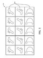
- FIG. 2 illustrates an exemplary die 52 , 54 including a three by five array of cavities 56 for simultaneously producing five parts 20 of three different automotive components.
- any desirable number of cavities 56 could be included in the hot forming apparatus 30 .
- the hot forming apparatus 30 with the plurality of cavities 56 provides a batch forming process which allows for manufacturing cost savings by reducing the amount of time required to produce each part 20 .
- the hot forming apparatus 30 also includes a plurality of cooling ports 58 extending along the cavities 56 for conveying a cooling fluid therethrough, such as water or any other cooling fluid.
- a cooling fluid such as water or any other cooling fluid.
- the quantity and temperature of water fed through the cooling ports 58 , as well as the shapes and locations of the cooling ports 58 can be chosen to achieve a desired quenching rate, and thus achieve the desired microstructure in the metal parts 20 .
- the quenching step includes rapidly cooling the shaped parts 20 to transform the austenitic microstructure to a martensitic microstructure.
- the hot forming apparatus 30 typically includes a controller (not shown) to actuate the dies 52 , 54 after one or more heated blanks 26 is properly placed between the dies 52 , 54 .
- the controller of the hot forming apparatus 30 can also adjust the amount of time that the parts 20 are quenched between the dies 52 , 54 .
- the exemplary system 22 also includes the blank feeder 28 disposed opposite the blank loader 48 and extending continuously from the furnace 24 to the hot forming apparatus 30 for conveying the heated blanks 26 to the hot forming apparatus 30 .
- the blank feeder 28 is preferably an indexing blank feeder and includes a plurality of third driven rollers 46 .
- the indexing feature of the blank feeder 28 can comprise a plurality of indexing fingers for aligning the heated blanks 26 in a predetermined position prior to entering the hot forming apparatus 30 .
- the blanks 26 are preferably positioned as close together as possible to reduce waste material during the hot forming step.
- the blank feeder 28 of the exemplary embodiment is movable vertically along the second sides of the shelves 32 for conveying the heated blanks 26 from each of the shelves 32 to the hot forming apparatus 30 .
- the third driven rollers 46 align with and are timed to move with the first driven rollers 42 of the shelves 32 at approximately the same rate.
- the blank feeder 28 could be removable, and another robot (not shown) could plug the blank feeder 28 into the furnace 24 .
- the blank feeder 28 is preferably insulated from the surrounding environment, or includes a heater (not shown) so that the heated blanks 26 are at a desired temperature when they enter the hot forming apparatus 30 .
- the system 22 can also include another robot (not shown) for lifting the heated blanks 26 off the blank feeder 28 and placing the heated blanks 26 in position relative to the cavities 56 of the hot forming apparatus 30 .
- the system 22 could include another method, such as a mechanical transfer system, for conveying the heated blanks 26 from the furnace 24 to the hot forming apparatus 30 .
- the system 22 also typically includes transfer bars (not shown) for removing the shaped parts 20 from the hot forming apparatus 30 and depositing them on a conveyor 60 .
- the conveyor 60 is disposed adjacent the hot forming apparatus 30 opposite the blank feeder 28 for conveying the shaped parts 20 away from the hot forming apparatus 30 .
- the shaped parts 20 could be removed from the hot forming apparatus 30 through another automated or manual process.
- the exemplary system 22 also comprises a system controller 62 including a computer, as shown in FIG. 1 , for controlling the blank feeder 28 , blank loader 48 , and conveyor 60 .
- the system controller 62 can instruct the blank loader 48 to move vertically along the first side of the furnace 24 in order to feed unheated blanks 26 into open chambers 36 of the furnace 24 and can instruct the blank feeder 28 to move vertically along the second side of the furnace 24 to convey the heated blanks 26 away from particular chambers 36 once they reach a predetermined temperature.
- the system controller 62 can instruct the blank loader 48 to automatically bypass any chambers 36 in the furnace 24 that are malfunctioning or have already been removed.
- the system 22 allows the system 22 to continue operating even if one or more heaters 34 in the furnace 24 is malfunctioning, which is in contrast to other known hot stamping systems that must be completely shut down if the heater is malfunctioning.
- the robot 50 , furnace 24 , and hot forming apparatus 30 are controlled independently by their own controllers, but the system controller 62 can share signals between the controllers of the robot 50 , furnace 24 , and hot forming apparatus 30 .
- the system controller 62 also verifies that each component of the system 22 is operating correctly in order to maximize the efficiency.
- the invention also provides a method for hot stamping a plurality of steel parts 20 providing reduced overhead costs per part 20 and requiring less floor space, compared to other hot forming methods.
- the method first includes feeding the blanks 26 onto the shelves 32 of the furnace 24 , typically by moving the unheated blanks 26 along the second driven rollers 44 of the blank loader 48 , through the first doors 38 of the chambers 36 , and onto the shelves 32 .
- the second driven rollers 44 are aligned with the first driven rollers 42 of one of the shelves 32 , and the first and second driven rollers 42 , 44 are timed to move together at approximately the same rate.
- the method also includes moving the blank loader 48 vertically relative to the first sides of the shelves 32 and feeding the unheated blanks 26 onto each of the shelves 32 .
- the method could include plugging the blank loader 48 into the furnace 24 .
- the method next includes heating the blanks 26 while the blanks 26 are disposed on the shelves 32 , and conveying the blanks 26 along the first driven rollers 42 through the furnace 24 .
- the metal blanks 26 remain in the furnace 24 for an amount of time capable of providing a desired microstructure.
- the blanks 26 can be heated while continuously moving through the furnace 24 , or while resting on the shelves 32 while the first driven rollers 42 remain stationary for a period of time.
- the first driven rollers 42 oscillate forward and backward with the blanks 26 .
- the oscillating first driven rollers 42 can prevent hot and cold spots along the blanks 26 , prevent the blanks 26 from drooping, and can help maintain the integrity of any coating applied to the blanks 26 .
- the method includes removing the chamber 36 containing the malfunctioning heater 34 , or removing the malfunctioning heater 34 and the adjacent shelf 32 , while continuing to heat the blanks 26 disposed on the other shelves 32 .
- the method also includes fixing the malfunctioning heater 34 while continuing to heat and convey the blanks 26 along the remaining shelves 32 of the furnace 24 .
- the method can include bypassing one of the shelves 32 of the furnace 24 when the heater 34 adjacent the shelf 32 is malfunctioning, or bypassing one of the chambers 36 when the heater 34 contained in the chamber 36 is malfunctioning.
- the method can continue manufacturing the shaped parts 20 even when one of the heaters 34 of the furnace 24 is down.
- the method next includes conveying the heated blanks 26 from the shelves 32 of the furnace 24 to the hot forming apparatus 30 .
- the conveying step includes moving the heated blanks 26 from the first driven rollers 42 of the furnace 24 to the third driven rollers 46 of the blank feeder 28 .
- the third driven rollers 46 align with the first driven roller 42 and are timed to move together with the first driven rollers 42 .
- the method includes moving the blank feeder 28 vertically along the stack of shelves 32 and conveying the heated blanks 26 from each of the shelves 32 to the hot forming apparatus 30 .
- the method includes isolating the heated blanks 26 from the outside environment while conveying them from the furnace 24 to the hot forming apparatus 30 , or heating the blanks 26 while conveying them from the furnace 24 to the hot forming apparatus 30 .
- the method includes stamping the heated blanks 26 between the dies 52 , 54 to form a plurality of the shaped parts 20 .
- the stamping step can include simultaneously shaping one of the blanks 26 into a plurality of shaped parts 20 using the plurality of cavities 56 in the hot forming apparatus 30 .
- the method then includes cooling each of the shaped parts 20 while the shaped parts 20 are disposed in the cavities 56 of the hot forming apparatus 30 .
- the cooling step includes cooling at least two of the shaped metal parts 20 in the cavities 56 at different rates to achieve different microstructures in the shaped metal parts 20 .
Landscapes
- Engineering & Computer Science (AREA)
- Mechanical Engineering (AREA)
- Chemical & Material Sciences (AREA)
- Physics & Mathematics (AREA)
- Thermal Sciences (AREA)
- General Engineering & Computer Science (AREA)
- Crystallography & Structural Chemistry (AREA)
- Materials Engineering (AREA)
- Metallurgy (AREA)
- Organic Chemistry (AREA)
- Shaping Metal By Deep-Drawing, Or The Like (AREA)
- Heat Treatment Of Articles (AREA)
- Tunnel Furnaces (AREA)
Priority Applications (3)
| Application Number | Priority Date | Filing Date | Title |
|---|---|---|---|
| US14/069,441 US9308564B2 (en) | 2012-11-28 | 2013-11-01 | Hot stamping system and method |
| CA2832257A CA2832257C (en) | 2012-11-28 | 2013-11-04 | Hot stamping system and method |
| MX2013014013A MX341019B (es) | 2012-11-28 | 2013-11-28 | Sistema y metodo de estampado en caliente. |
Applications Claiming Priority (2)
| Application Number | Priority Date | Filing Date | Title |
|---|---|---|---|
| US201261730667P | 2012-11-28 | 2012-11-28 | |
| US14/069,441 US9308564B2 (en) | 2012-11-28 | 2013-11-01 | Hot stamping system and method |
Publications (2)
| Publication Number | Publication Date |
|---|---|
| US20140144198A1 US20140144198A1 (en) | 2014-05-29 |
| US9308564B2 true US9308564B2 (en) | 2016-04-12 |
Family
ID=50772083
Family Applications (1)
| Application Number | Title | Priority Date | Filing Date |
|---|---|---|---|
| US14/069,441 Active 2034-10-14 US9308564B2 (en) | 2012-11-28 | 2013-11-01 | Hot stamping system and method |
Country Status (3)
| Country | Link |
|---|---|
| US (1) | US9308564B2 (es) |
| CA (1) | CA2832257C (es) |
| MX (1) | MX341019B (es) |
Cited By (7)
| Publication number | Priority date | Publication date | Assignee | Title |
|---|---|---|---|---|
| US10280478B2 (en) * | 2015-12-18 | 2019-05-07 | GM Global Technology Operations LLC | Production line and tool arrangement for producing a hot formed component from a blank |
| US10399519B2 (en) | 2017-06-16 | 2019-09-03 | Ford Global Technologies, Llc | Vehicle bumper beam with varied strength zones |
| US10549381B2 (en) * | 2013-10-31 | 2020-02-04 | Magna International Inc. | System and method for hot stamping of components |
| US10556624B2 (en) | 2017-06-16 | 2020-02-11 | Ford Global Technologies, Llc | Vehicle underbody component protection assembly |
| US10633037B2 (en) | 2017-06-16 | 2020-04-28 | Ford Global Technologies, Llc | Vehicle underbody assembly with thermally treated rear rail |
| US11141769B2 (en) | 2017-06-16 | 2021-10-12 | Ford Global Technologies, Llc | Method and apparatus for forming varied strength zones of a vehicle component |
| US11740023B2 (en) * | 2016-12-22 | 2023-08-29 | Autotech Engineering, S.L. | Method for heating a blank and heating system |
Families Citing this family (15)
| Publication number | Priority date | Publication date | Assignee | Title |
|---|---|---|---|---|
| US9032605B2 (en) * | 2009-06-09 | 2015-05-19 | Shiloh Industries, Inc. | Apparatus, system and method for manufacturing metal parts |
| DE102011120681A1 (de) * | 2011-12-08 | 2013-06-13 | Linde Aktiengesellschaft | Anlage und Verfahren zum Vorwärmen von Platinen beim Warmumformen |
| DE102012218159B4 (de) * | 2012-10-04 | 2018-02-08 | Ebner Industrieofenbau Gmbh | Handhabungseinrichtung |
| US9308564B2 (en) * | 2012-11-28 | 2016-04-12 | Magna International Inc. | Hot stamping system and method |
| US9222729B2 (en) * | 2012-12-07 | 2015-12-29 | Linde Aktiengesellschaft | Plant and method for hot forming blanks |
| CN104399858B (zh) * | 2014-12-09 | 2017-06-27 | 周剑管 | 红冲加热及其成型流水线 |
| MX2016004689A (es) * | 2015-04-15 | 2017-04-25 | Magna Int Inc | Horno de multiples aberturas de formacion de aluminio en caliente y linea de produccion. |
| ES2667769T3 (es) | 2015-10-13 | 2018-05-14 | Autotech Engineering, A.I.E. | Sistema de centrado para preformas |
| CA2933088A1 (en) * | 2016-03-24 | 2017-09-24 | The Electromac Group, Inc. | Hot stamp cell |
| WO2017180193A1 (en) * | 2016-04-11 | 2017-10-19 | Consolidated Engineering Company, Inc. | Internal unstacker for a heat treatment furnace |
| BR102016030406A2 (pt) * | 2016-12-23 | 2018-07-17 | Aethra Sist Automotivos S/A | sistema de estampagem a quente para produção de um conjunto de peças |
| US20190105731A1 (en) * | 2017-10-06 | 2019-04-11 | GM Global Technology Operations LLC | Hot formed bonding in sheet metal panels |
| CN108817207B (zh) * | 2018-05-23 | 2020-06-05 | 安徽中知众创知识产权运营有限公司 | 一种自动上料的汽车零部件冲压机 |
| CN111468578B (zh) * | 2020-04-14 | 2022-03-04 | 杭州丰衡机电有限公司 | 一种连续模自动送料机构 |
| CN117943450B (zh) * | 2024-03-26 | 2024-07-19 | 河北华曙新能源汽车科技有限公司 | 汽车底盘部件冲压成型工艺 |
Citations (5)
| Publication number | Priority date | Publication date | Assignee | Title |
|---|---|---|---|---|
| US7137201B2 (en) * | 2000-10-07 | 2006-11-21 | Daimlerchrysler Ag | Method and apparatus for the production of locally reinforced sheet-metal mouldings and products made thereby |
| US20090155615A1 (en) * | 2007-12-18 | 2009-06-18 | Gm Global Technology Operations, Inc. | Designed orientation for welded automotive structural components made of press hardened steel |
| US20110283851A1 (en) * | 2010-05-21 | 2011-11-24 | Thyssenkrupp Sofedit S.A.S. | Method and hot forming system for producing press-hardened formed components of sheet steel |
| US20140144198A1 (en) * | 2012-11-28 | 2014-05-29 | John Richard Potocki | Hot Stamping System And Method |
| US9032605B2 (en) * | 2009-06-09 | 2015-05-19 | Shiloh Industries, Inc. | Apparatus, system and method for manufacturing metal parts |
-
2013
- 2013-11-01 US US14/069,441 patent/US9308564B2/en active Active
- 2013-11-04 CA CA2832257A patent/CA2832257C/en active Active
- 2013-11-28 MX MX2013014013A patent/MX341019B/es active IP Right Grant
Patent Citations (5)
| Publication number | Priority date | Publication date | Assignee | Title |
|---|---|---|---|---|
| US7137201B2 (en) * | 2000-10-07 | 2006-11-21 | Daimlerchrysler Ag | Method and apparatus for the production of locally reinforced sheet-metal mouldings and products made thereby |
| US20090155615A1 (en) * | 2007-12-18 | 2009-06-18 | Gm Global Technology Operations, Inc. | Designed orientation for welded automotive structural components made of press hardened steel |
| US9032605B2 (en) * | 2009-06-09 | 2015-05-19 | Shiloh Industries, Inc. | Apparatus, system and method for manufacturing metal parts |
| US20110283851A1 (en) * | 2010-05-21 | 2011-11-24 | Thyssenkrupp Sofedit S.A.S. | Method and hot forming system for producing press-hardened formed components of sheet steel |
| US20140144198A1 (en) * | 2012-11-28 | 2014-05-29 | John Richard Potocki | Hot Stamping System And Method |
Cited By (7)
| Publication number | Priority date | Publication date | Assignee | Title |
|---|---|---|---|---|
| US10549381B2 (en) * | 2013-10-31 | 2020-02-04 | Magna International Inc. | System and method for hot stamping of components |
| US10280478B2 (en) * | 2015-12-18 | 2019-05-07 | GM Global Technology Operations LLC | Production line and tool arrangement for producing a hot formed component from a blank |
| US11740023B2 (en) * | 2016-12-22 | 2023-08-29 | Autotech Engineering, S.L. | Method for heating a blank and heating system |
| US10399519B2 (en) | 2017-06-16 | 2019-09-03 | Ford Global Technologies, Llc | Vehicle bumper beam with varied strength zones |
| US10556624B2 (en) | 2017-06-16 | 2020-02-11 | Ford Global Technologies, Llc | Vehicle underbody component protection assembly |
| US10633037B2 (en) | 2017-06-16 | 2020-04-28 | Ford Global Technologies, Llc | Vehicle underbody assembly with thermally treated rear rail |
| US11141769B2 (en) | 2017-06-16 | 2021-10-12 | Ford Global Technologies, Llc | Method and apparatus for forming varied strength zones of a vehicle component |
Also Published As
| Publication number | Publication date |
|---|---|
| US20140144198A1 (en) | 2014-05-29 |
| CA2832257A1 (en) | 2014-05-28 |
| MX2013014013A (es) | 2014-11-20 |
| MX341019B (es) | 2016-08-04 |
| CA2832257C (en) | 2019-11-12 |
Similar Documents
| Publication | Publication Date | Title |
|---|---|---|
| US9308564B2 (en) | Hot stamping system and method | |
| CN101896292B (zh) | 热压成形装置以及热压成形方法 | |
| WO2014051014A1 (ja) | 成形装置及び成形方法 | |
| US20210237138A1 (en) | Conduction pre-heating of sheet for hot forming | |
| MX2013014246A (es) | Metodo para calentar un componente formado para una subsecuente operacion de conformado en caliente y horno continuo para calentar regionalmente un componente formado precalentado a una temperatura predeterminada a una temperatura superior. | |
| JP2008296237A (ja) | 多段式加熱装置 | |
| RU2709320C1 (ru) | Устройство для горячего прессования | |
| CN106929659A (zh) | 热处理炉以及用于对预涂层的钢板坯进行热处理的方法和用于制造机动车构件的方法 | |
| CN103993137A (zh) | 热处理作业线和操作热处理作业线的方法 | |
| JP2018511485A (ja) | 被加工物を熱間プレス成形するための方法、炉装置及び設備 | |
| CN102051457A (zh) | 具有过热温度的室式炉 | |
| CN101440423B (zh) | 真空热处理自动控制炉 | |
| KR20150029354A (ko) | 유도가열을 이용한 열처리 장치 | |
| US6457342B2 (en) | Forging device and method therefor | |
| CN107814475A (zh) | 一种玻璃三维成型热压系统及其工艺方法 | |
| EP3081888B1 (en) | Aluminum warm forming multi-opening oven and production line | |
| CN104388641A (zh) | 一种基于坯料形状特征的柔性化快速加热方法 | |
| CN207227473U (zh) | 用于输送至少一个被加热的组件的设备 | |
| EP1569874B1 (en) | Machine and process for shaping, annealing and quenching glass sheets, or similar materials | |
| JP2015094023A (ja) | 加熱装置 | |
| JP2005291515A (ja) | 連続焼成炉および連続焼成方法 | |
| CN110088018A (zh) | 用于传送至少一个加热部件的装置 | |
| US12072150B2 (en) | Heating furnace | |
| JP2015094025A (ja) | 加熱方法 |
Legal Events
| Date | Code | Title | Description |
|---|---|---|---|
| AS | Assignment |
Owner name: MAGNA INTERNATIONAL INC., CANADA Free format text: ASSIGNMENT OF ASSIGNORS INTEREST;ASSIGNORS:POTOCKI, JOHN RICHARD;WISEMAN, TAD STEWART;REEL/FRAME:037912/0984 Effective date: 20160307 |
|
| STCF | Information on status: patent grant |
Free format text: PATENTED CASE |
|
| MAFP | Maintenance fee payment |
Free format text: PAYMENT OF MAINTENANCE FEE, 4TH YEAR, LARGE ENTITY (ORIGINAL EVENT CODE: M1551); ENTITY STATUS OF PATENT OWNER: LARGE ENTITY Year of fee payment: 4 |
|
| MAFP | Maintenance fee payment |
Free format text: PAYMENT OF MAINTENANCE FEE, 8TH YEAR, LARGE ENTITY (ORIGINAL EVENT CODE: M1552); ENTITY STATUS OF PATENT OWNER: LARGE ENTITY Year of fee payment: 8 |