US927770A - Incandescent gas-lamp. - Google Patents
Incandescent gas-lamp. Download PDFInfo
- Publication number
- US927770A US927770A US44727908A US1908447279A US927770A US 927770 A US927770 A US 927770A US 44727908 A US44727908 A US 44727908A US 1908447279 A US1908447279 A US 1908447279A US 927770 A US927770 A US 927770A
- Authority
- US
- United States
- Prior art keywords
- cover
- reflector
- lamp
- gas
- hell
- Prior art date
- Legal status (The legal status is an assumption and is not a legal conclusion. Google has not performed a legal analysis and makes no representation as to the accuracy of the status listed.)
- Expired - Lifetime
Links
- 238000004880 explosion Methods 0.000 description 6
- 239000011521 glass Substances 0.000 description 3
- 240000000233 Melia azedarach Species 0.000 description 1
- 238000010276 construction Methods 0.000 description 1
- 239000000203 mixture Substances 0.000 description 1
- 230000000284 resting effect Effects 0.000 description 1
- 238000009423 ventilation Methods 0.000 description 1
Images
Classifications
-
- B—PERFORMING OPERATIONS; TRANSPORTING
- B60—VEHICLES IN GENERAL
- B60Q—ARRANGEMENT OF SIGNALLING OR LIGHTING DEVICES, THE MOUNTING OR SUPPORTING THEREOF OR CIRCUITS THEREFOR, FOR VEHICLES IN GENERAL
- B60Q1/00—Arrangement of optical signalling or lighting devices, the mounting or supporting thereof or circuits therefor
- B60Q1/02—Arrangement of optical signalling or lighting devices, the mounting or supporting thereof or circuits therefor the devices being primarily intended to illuminate the way ahead or to illuminate other areas of way or environments
- B60Q1/04—Arrangement of optical signalling or lighting devices, the mounting or supporting thereof or circuits therefor the devices being primarily intended to illuminate the way ahead or to illuminate other areas of way or environments the devices being headlights
- B60Q1/06—Arrangement of optical signalling or lighting devices, the mounting or supporting thereof or circuits therefor the devices being primarily intended to illuminate the way ahead or to illuminate other areas of way or environments the devices being headlights adjustable, e.g. remotely-controlled from inside vehicle
- B60Q1/08—Arrangement of optical signalling or lighting devices, the mounting or supporting thereof or circuits therefor the devices being primarily intended to illuminate the way ahead or to illuminate other areas of way or environments the devices being headlights adjustable, e.g. remotely-controlled from inside vehicle automatically
- B60Q1/12—Arrangement of optical signalling or lighting devices, the mounting or supporting thereof or circuits therefor the devices being primarily intended to illuminate the way ahead or to illuminate other areas of way or environments the devices being headlights adjustable, e.g. remotely-controlled from inside vehicle automatically due to steering position
- B60Q1/124—Arrangement of optical signalling or lighting devices, the mounting or supporting thereof or circuits therefor the devices being primarily intended to illuminate the way ahead or to illuminate other areas of way or environments the devices being headlights adjustable, e.g. remotely-controlled from inside vehicle automatically due to steering position by mechanical means
Definitions
- This invention relates to incandescent aslamps and has for its object the constl'uel ion of such lamps in a manner that will prevent explosions therein and the other advantages hereinafter pointed out.
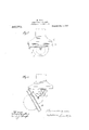
- Figure 1 is an clevation of an incandescent gasdamp made in :wcordance with this invention showing the parts thorool when closed. and in normal position;
- Fig. 2 is an elevation of the same amp shmviug the parts thereof when opened to permit ignition of the Bunsen flame.
- the present ii'rvention prevents such an explosion by the arrangrancnt that the rellcctor is automatieally moved out. of the outer hell cover when the latter is lot down and again :uitomatically moved into its place when the hell cover is swung hack into position; in this way the int crior of the bell cover is thoroughly ventilated and any gas which has collected there is removed.
- the reflector (A) is on the one side hinged to the hell cover (1)) at (B and is held on the other side by a short. chain (l,), when the hell cover is let down; normally, however, when the bell cover is in place, the reflector rests within the mouth of this hell cover, being supported in any suitable manner, as by hooks attached to the reflector and resting upon pins secured to the hell cover, as illustrated at (B 011 one side of the reflector, the support therefor, consisting, as shown, of a hook and pin.
- the hook shown on the opposite side of the reflector may rest on a like pin, but does not form a hinge with the pin.
- the chain (13,) is of such length that when the hell cover is let down the reflector will remain suspended half way between the burner and the outer bell cover (1)).
- the latter is hinged at (E) to the body of the lamp containing the burner
- the chain (B acts to withdraw the re flcotor from the cover, when the cover is let down, and the chain aids in supporting the reflector while the cover is down, as shown in Fig. 2.
- the chain being flexible or collapsible, does not interfere with the return of the reflector to its normal position, as shown in Fig. 1, when the cover, after being let down, is swung back into its normal position, carrying the reflector with it.
Landscapes
- Engineering & Computer Science (AREA)
- Mechanical Engineering (AREA)
- Non-Portable Lighting Devices Or Systems Thereof (AREA)
Description
H. BLAU.
INGANDESGENT GAS LAMP.
APYLIOATION FILED AUG. 6, 1908..
Patented July 13, 1909 z m MM ll ERMANN JHIAU, ()F AUGSBURG, GERMANY.
INCANDESGENT GAS-LAMP.
Specification of Letters Patent.
Application filed August 6, 1908.
Patented July 13, 1909.
Serial No. 447,279.
To all whom it may concern:
Be it known that l, Hummus Bmu, citizen of Germany, residing at i'\llt1'8l)lll'f, Bavaria, Germany, have invented certain new and useful lmprm'emcnts in incandescent Gas-.lian'ips; and 1 do hereby declare the following to he a full, clear, and exact description of the invention, such as will enable others skilled in the art to which is appertains to make and use the smile.
This invention relates to incandescent aslamps and has for its object the constl'uel ion of such lamps in a manner that will prevent explosions therein and the other advantages hereinafter pointed out. i i
In the accompanying drawings forming part ol this specification, Figure 1 is an clevation of an incandescent gasdamp made in :wcordance with this invention showing the parts thorool when closed. and in normal position; Fig. 2 is an elevation of the same amp shmviug the parts thereof when opened to permit ignition of the Bunsen flame.
.la the ease of incamlescent gas lamps of large dimensions, such as are used for lightin; railway carriages, in which the incandescent body is mounted on or in the reflector, the latter being arranged within the outer glass hell cover or shade of the lamp and reuuiivahlo with the same, it frequently happens that when the lamp is closed after lighting; the Bunsen flame an explosion OCCLIIS which may injure the. mantle or glass shade of the lamp. This explosion is caused by the which collects in the space inelosed h; the reflector and the outer hell cover wh the gas tap is turned on before letting, down said outer cover with the reflector. After letting down the outer cover with the reflector and then lighting, the Bunsen flame, the outer bell glass together with the reflector is swung hack into place, and it is then that the mixture of gas and air contained within said hell cover is ignited and causes an explosion.
The present ii'rvention prevents such an explosion by the arrangrancnt that the rellcctor is automatieally moved out. of the outer hell cover when the latter is lot down and again :uitomatically moved into its place when the hell cover is swung hack into position; in this way the int crior of the bell cover is thoroughly ventilated and any gas which has collected there is removed.
In the form of construction here illustrated in Figs. l and 2 of the drawings, the reflector (A) is on the one side hinged to the hell cover (1)) at (B and is held on the other side by a short. chain (l,), when the hell cover is let down; normally, however, when the bell cover is in place, the reflector rests within the mouth of this hell cover, being supported in any suitable manner, as by hooks attached to the reflector and resting upon pins secured to the hell cover, as illustrated at (B 011 one side of the reflector, the support therefor, consisting, as shown, of a hook and pin. should, as stated, form a hinge, as at (B The hook shown on the opposite side of the reflector may rest on a like pin, but does not form a hinge with the pin. The chain (13,) is of such length that when the hell cover is let down the reflector will remain suspended half way between the burner and the outer bell cover (1)). The latter is hinged at (E) to the body of the lamp containing the burner The chain (B acts to withdraw the re flcotor from the cover, when the cover is let down, and the chain aids in supporting the reflector while the cover is down, as shown in Fig. 2. The chain, being flexible or collapsible, does not interfere with the return of the reflector to its normal position, as shown in Fig. 1, when the cover, after being let down, is swung back into its normal position, carrying the reflector with it.
The action of this device is as follows: )Vhen the hell cover (1)), containing the reflcetor (A), is let down, the latter will first take part in the movement of the former until the Bunsen hurner becomes accessible, and will then, by means of the chain (13,), be moved out of said bell cover, thereby allowhug the therein collected to escape. When the hell cover is swung back the reflector will again take up its former position in the hell cover. In this way a thorough ventilation of the interior space of the bell cover is'attained, and an explosion therefore becomes impossible.
What I claim as my invention and desire to secure by Letters Patent, is;
1. In an iucaiulcsceut gas-lamp, the combination of a part provided with a burner, a cover for said part, a reflector, a hinge connecting the reflector with the cover and means for witlulrawinp the reflector from the cover during the opening movement of the-cover, substantially as described.
2. in an incaiulcscent gas-lamp, the combinatiim of a. part provided with a burner,
3. In an incandescent gas-lamp, the combinntion of a, part provided with a burner, a cover for said port, chinge connecting said cover With said part, it reflector provided with an incandescent body, a. hinge connectingthe reflector With the cover and e support connecting the reflector with the part provided with the burner, said support being flexible and of such length that when the cover is let down the reflector will be moved out of the cover, substantially as described.
4. in an incandescent gas-lamp, the combinntion of a part provided with a burner, a cover for said part, L hinge connecting the cover with said part, a reflector carried by said cover and movable therewith, a hinge connecting the reflector with the cover and a support connecting the reflector with the part provided with the burner, said support being flexible and of such length that when the cover is let down the reflector Will be moved out of the cover, substantially as described.
5. In an incandescent gas-lemp, the combination of it cover and a reflector inelosing a space between them, a hinge connecting the reflector with the cover and to withdrew the reflector from the eover When the cover is Withdrawn from the gas-lamp, substantially as described.
6. In an incandescent gas-lamp, the cornbinetion of a cover and a. reflector inclosing a space between them, hinge upon which. the cover can turn, a hinge'connecting the reflector with the cover and nieensto Withdraw the reflector from the cover when the cover during its opening movement is turned upon its hinge, substantially as described.
7. In an incandescent ga s-h m the combination of a part provided wit it burner, a cover and o reflector in dosing a space between them, :1 l'iinge upo: which the cover can turn, reflector cert fl 'by the cover and movable therewith, hinge connecting the reflector witli the cover and means to with drew the reflector i'roiin the cover when the cover during its opening movement is turned upon its hinge, snbstmitially as described.
In testimony whereof I hereunto e-flix my signature in the presence of two Witnesses.
HERMAN-N B AU.
Witnesses:
ifdArniLnn it. linens, Lonrs MUELLUR.
Priority Applications (1)
| Application Number | Priority Date | Filing Date | Title |
|---|---|---|---|
| US44727908A US927770A (en) | 1908-08-06 | 1908-08-06 | Incandescent gas-lamp. |
Applications Claiming Priority (1)
| Application Number | Priority Date | Filing Date | Title |
|---|---|---|---|
| US44727908A US927770A (en) | 1908-08-06 | 1908-08-06 | Incandescent gas-lamp. |
Publications (1)
| Publication Number | Publication Date |
|---|---|
| US927770A true US927770A (en) | 1909-07-13 |
Family
ID=2996196
Family Applications (1)
| Application Number | Title | Priority Date | Filing Date |
|---|---|---|---|
| US44727908A Expired - Lifetime US927770A (en) | 1908-08-06 | 1908-08-06 | Incandescent gas-lamp. |
Country Status (1)
| Country | Link |
|---|---|
| US (1) | US927770A (en) |
-
1908
- 1908-08-06 US US44727908A patent/US927770A/en not_active Expired - Lifetime
Similar Documents
| Publication | Publication Date | Title |
|---|---|---|
| US927770A (en) | Incandescent gas-lamp. | |
| US1683662A (en) | Toy pistol | |
| US856960A (en) | Gas-lamp. | |
| US1180175A (en) | Gas-burner. | |
| US1321915A (en) | heidelberg | |
| US855926A (en) | Globe-closure for electric-arc lamps. | |
| US388727A (en) | Henry shaw | |
| US1166091A (en) | Lamp or light. | |
| US715885A (en) | Lamp. | |
| GB191504770A (en) | Improvements in and connected with Gas-fires. | |
| US630820A (en) | Egg-tester. | |
| US417030A (en) | Thomas w | |
| US1117521A (en) | Guard for inverted incandescent mantles. | |
| US635567A (en) | Flash-light lamp. | |
| US650668A (en) | Electric lighter for incandescent burners. | |
| US216398A (en) | Improvement in ventilation for mills | |
| US713125A (en) | Lamp. | |
| US618140A (en) | Yictoe h | |
| GB190905010A (en) | Improvements in or relating to Incandescent Mantles for Gas Lighting. | |
| US735682A (en) | Hydrocarbon-lamp. | |
| USRE7511E (en) | Improvement in shade-holders for lamps | |
| US934309A (en) | Incandescent gas-lamp. | |
| US588379A (en) | bellamy | |
| US817081A (en) | Incandescent gas-light. | |
| US1100600A (en) | Gas-lighter. |