US9276638B2 - Coupling circuits for power line communication devices - Google Patents
Coupling circuits for power line communication devices Download PDFInfo
- Publication number
- US9276638B2 US9276638B2 US13/229,041 US201113229041A US9276638B2 US 9276638 B2 US9276638 B2 US 9276638B2 US 201113229041 A US201113229041 A US 201113229041A US 9276638 B2 US9276638 B2 US 9276638B2
- Authority
- US
- United States
- Prior art keywords
- coupled
- circuit
- line interface
- plc
- capacitors
- Prior art date
- Legal status (The legal status is an assumption and is not a legal conclusion. Google has not performed a legal analysis and makes no representation as to the accuracy of the status listed.)
- Active, expires
Links
- 230000008878 coupling Effects 0.000 title claims abstract description 56
- 238000010168 coupling process Methods 0.000 title claims abstract description 56
- 238000005859 coupling reaction Methods 0.000 title claims abstract description 56
- 238000004891 communication Methods 0.000 title claims abstract description 19
- 239000003990 capacitor Substances 0.000 claims abstract description 48
- 230000005540 biological transmission Effects 0.000 claims description 12
- 230000004044 response Effects 0.000 claims description 9
- 238000010586 diagram Methods 0.000 description 12
- 230000008901 benefit Effects 0.000 description 2
- 238000013480 data collection Methods 0.000 description 2
- 238000000034 method Methods 0.000 description 2
- 238000012986 modification Methods 0.000 description 2
- 230000004048 modification Effects 0.000 description 2
- 230000007935 neutral effect Effects 0.000 description 2
- 230000001052 transient effect Effects 0.000 description 2
- 238000004378 air conditioning Methods 0.000 description 1
- 238000013459 approach Methods 0.000 description 1
- 230000001413 cellular effect Effects 0.000 description 1
- 239000004020 conductor Substances 0.000 description 1
- 230000001276 controlling effect Effects 0.000 description 1
- 230000009977 dual effect Effects 0.000 description 1
- 230000005611 electricity Effects 0.000 description 1
- 230000006870 function Effects 0.000 description 1
- 238000012544 monitoring process Methods 0.000 description 1
- 230000006855 networking Effects 0.000 description 1
- 238000012545 processing Methods 0.000 description 1
- 230000001105 regulatory effect Effects 0.000 description 1
- 230000003068 static effect Effects 0.000 description 1
- 230000001360 synchronised effect Effects 0.000 description 1
Images


Classifications
-
- H—ELECTRICITY
- H04—ELECTRIC COMMUNICATION TECHNIQUE
- H04B—TRANSMISSION
- H04B3/00—Line transmission systems
- H04B3/54—Systems for transmission via power distribution lines
- H04B3/56—Circuits for coupling, blocking, or by-passing of signals
Definitions
- Embodiments are directed, in general, to power line communications, and, more specifically, to coupling circuits for power line communication (PLC) devices.
- PLC power line communication
- Power line communications include systems for communicating data over the same medium (i.e., a wire or conductor) that is also used to transmit electric power to residences, buildings, factories, and other premises.
- PLC systems may enable a wide array of applications, including, for example, automatic meter reading and load control (i.e., utility-type applications), automotive uses (e.g., charging electric cars), home automation (e.g., controlling appliances, lights, etc.), and/or computer networking (e.g., Internet access), to name only a few.
- PLC Physical Downlink Control
- G.hn ITU-T G.hn (e.g., G.9960 and G.9961) specifications.
- a PLC device may include a processor and a coupling circuit coupled to the processor.
- the processor may include a digital signal processor (DSP), an application specific integrated circuit (ASIC), a system-on-chip (SoC) circuit, a field-programmable gate array (FPGA), a microprocessor, or a microcontroller.
- the coupling circuit may comprise a transmitter path and a receiver path.
- the transmitter path may include a first amplifier, a first capacitor coupled to the first amplifier, a first transformer coupled to the first capacitor, and a plurality of line interface coupling circuits coupled to the first transformer.
- Each of the line interface coupling circuits may be configured to be connected to a different phase of an electrical power circuit.
- the receiver path may include a plurality of capacitors, a filter network coupled to the plurality of capacitors, and a second amplifier coupled to the filter network.
- Each of the plurality of capacitors may be coupled to a corresponding one of the line interface circuits.
- the filter network may include a second transformer.
- the first amplifier may be configured to operate in a low impedance mode during a transmission operation and in a high impedance mode during a receiving operation.
- the plurality of capacitors may be configured to linearly combine signals received through the plurality of line interface coupling circuits.
- Each of the plurality of line interface coupling circuits may be configured as a high-pass filter, and the filter network may be configured as a band-pass filter.
- the band-pass filter may be dynamically adjustable to select a frequency band corresponding to a frequency selected in response to an indication that the circuit is configured to operate in one of a plurality of different receiving modes.
- the coupling circuit may also comprise a plurality of high-voltage switches, where each of the plurality of high-voltage switches is coupled between the first transformer and a corresponding one of the plurality of line interface coupling circuits.
- the plurality of high-voltage switches may be configured such that, in response to an indication that the circuit is operating in a particular transmitting mode, at least one of the plurality of high-voltage switches is open.
- the number of high-voltage switches that may be open or closed during transmission may depend upon whether the PLC device is operating in a broadcast, multicast, or unicast transmission mode.
- the plurality of high-voltage switches may be configured such that, in response to an indication that the circuit is configured to operate in a particular receiving mode, one or more of the plurality of high-voltage switches may be closed.
- the number of high-voltage switches that may be open or closed during reception may depend upon whether the PLC device is expecting to receive signals in a broadcast, multicast, or unicast mode. For example, if the device is set to receive signals in broadcast mode (or in a unicast mode through a known phase), a single one of high-voltage switches may be closed, thus further increasing the impedance of the receive path.
- FIG. 1 is a diagram of a PLC environment according to some embodiments.
- FIG. 2 is a block diagram of a PLC device or modem according to some embodiments.
- FIG. 3 is a block diagram of a PLC gateway according to some embodiments.
- FIG. 4 is a block diagram of a PLC data concentrator according to some embodiments.
- FIG. 5 is a block diagram of a prior art PLC coupling circuit.
- FIG. 6 is a block diagram of a PLC coupling circuit according to some embodiments.
- FIG. 7 is a block diagram of a PLC coupling circuit implemented with high-voltage switches according to some embodiments.
- Medium voltage (MV) power lines 103 from substation 101 typically carry voltage in the tens of kilovolts range.
- Transformer 104 steps the MV power down to low voltage (LV) power on LV lines 105 , carrying voltage in the range of 100-240 VAC.
- Transformer 104 is typically designed to operate at very low frequencies in the range of 50-60 Hz.
- Transformer 104 does not generally allow high frequencies, such as signals greater than 100 KHz, to pass between LV lines 105 and MV lines 103 .
- LV lines 105 feed power to customers via meters 106 a - n , which are typically mounted on the outside of residences 102 a - n .
- premises 102 a - n may include any type of building, facility, or other location where electric power is received and/or consumed.
- a breaker panel such as panel 107 , provides an interface between meter 106 n and electrical wires 108 within residence 102 n . Electrical wires 108 deliver power to outlets 110 , switches 111 and other electric devices within residence 102 n.
- the power line topology illustrated in FIG. 1 may be used, for example, to deliver high-speed communications to residences 102 a - n .
- power line communications modems or gateways 112 a - n may be coupled to LV power lines 105 at meter 106 a - n .
- PLC modems or gateways 112 a - n may be used to transmit and receive data signals over MV/LV lines 103 / 105 .
- Such data signals may be used to support metering and power delivery applications (e.g., smart grid applications), communication systems, high speed Internet, telephony, video conferencing, and video delivery, to name a few.
- An illustrative method for transmitting data over power lines may use, for example, a carrier signal having a frequency different from that of the power signal.
- the carrier signal may be modulated by the data, for example, using an orthogonal frequency division multiplexing (OFDM) scheme or the like.
- OFDM orthogonal frequency division multiplexing
- PLC modems or gateways 112 a - n at premises 102 a - n use the MV/LV power grid to carry data signals to and from PLC data concentrator 114 without requiring additional wiring.
- Concentrator 114 may be coupled to either MV line 103 or LV line 105 .
- Modems or gateways 112 a - n may support applications such as high-speed broadband Internet links, narrowband control applications, low bandwidth data collection applications, or the like. In a home environment, for example, modems or gateways 112 a - n may further enable home and building automation in heat and air conditioning, lighting, and security.
- PLC modems or gateways 112 a - n may enable alternating current (AC) or direct current (DC) charging of electric vehicles and other appliances.
- AC or DC charger An example of an AC or DC charger is illustrated as PLC device 113 .
- power line communication networks may provide street lighting control and remote power meter data collection.
- One or more concentrators 114 may be coupled to control center 130 (e.g., a utility company) via network 120 .
- Network 120 may include, for example, an IP-based network, the Internet, a cellular network, a WiFi network, a WiMax network, or the like.
- control center 130 may be configured to collect power consumption and other types of information from gateway(s) 112 and/or device(s) 113 through concentrator(s) 114 .
- control center 130 may be configured to implement smart grid policies and other regulatory or commercial rules by communicating such rules to each gateway(s) 112 and/or device(s) 113 through concentrator(s) 114 .
- FIG. 2 is a block diagram of PLC device 113 according to some embodiments.
- AC interface 201 may be coupled to electrical wires 108 a and 108 b (e.g., phase and neutral) inside of premises 112 n in a manner that allows PLC device 113 to switch the connection between wires 108 a and 108 b off using a switching circuit or the like. In other embodiments, however, AC interface 201 may be connected to a single wire 108 (i.e., phase only) and without providing such switching capabilities.
- AC interface 201 includes a coupling circuit that allows PLC engine 202 to receive and transmit PLC signals over wires 108 a - b . Embodiments of coupling circuits suitable for use as part of AC interface 201 are disclosed below with respect to FIGS. 6 and 7 .
- PLC device 113 may be a PLC modem. Additionally or alternatively, PLC device 113 may be a part of a smart grid device (e.g., an AC or DC charger, a meter, etc.), an appliance, or a control module for other electrical elements located inside or outside of premises 112 n (e.g., street lighting, etc.).
- a smart grid device e.g., an AC or DC charger, a meter, etc.
- appliance e.g., a smart grid device
- control module for other electrical elements located inside or outside of premises 112 n e.g., street lighting, etc.
- PLC engine 202 may be configured to transmit and/or receive PLC signals over wires 108 a and/or 108 b via AC interface 201 using a particular frequency band.
- PLC engine 202 may be configured to generate OFDM signals, although other types of modulation schemes may be used.
- PLC engine 202 may include or otherwise be configured to communicate with metrology or monitoring circuits (not shown) that are in turn configured to measure power consumption characteristics of certain devices or appliances via wires 108 , 108 a , and/or 108 b .
- PLC engine 202 may receive such power consumption information, encode it as one or more PLC signals, and transmit it over wires 108 , 108 a , and/or 108 b to higher-level PLC devices (e.g., PLC gateway 112 n , data concentrator 114 , etc.) for further processing.
- PLC engine 202 may receive instructions and/or other information from such higher-level PLC devices encoded in PLC signals, for example, to allow PLC engine 202 to select a particular frequency band in which to operate.
- the frequency band in which PLC device 113 operates may be selected or otherwise allocated based, at least in part, upon an application profile and/or a device class associated with PLC device 113 .
- FIG. 3 is a block diagram of PLC gateway 112 according to some embodiments.
- gateway engine 301 is coupled to AC interface 302 , local communication interface 304 , and frequency band usage database 304 .
- AC interface 302 is coupled to meter 106
- local communication interface 304 is coupled to one or more of a variety of PLC devices such as, for example, PLC device 113 .
- AC interface 302 may also include coupling circuits that facilitate the transmission and reception of PLC signals over one or more power line(s).
- Local communication interface 304 may provide a variety of communication protocols such as, for example, ZigBee®, Bluetooth®, WiFi, WiMax, Ethernet, etc., which may enable gateway 112 to communicate with a wide variety of different devices and appliances.
- gateway engine 301 may be configured to collect communications from PLC device 113 and/or other devices, as well as meter 106 , and serve as an interface between these various devices and PLC data concentrator 114 .
- Gateway engine 301 may also be configured to allocate frequency bands to specific devices and/or to provide information to such devices that enable them to self-assign their own operating frequencies.
- PLC gateway 112 may be disposed within or near premises 102 n and serve as a gateway to all PLC communications to and/or from premises 102 n . In other embodiments, however, PLC gateway 112 may be absent and PLC devices 113 (as well as meter 106 n and/or other appliances) may communicate directly with PLC data concentrator 114 . When PLC gateway 112 is present, it may include database 304 with records of frequency bands currently used, for example, by various PLC devices 113 within premises 102 n . An example of such a record may include, for instance, device identification information (e.g., serial number, device ID, etc.), application profile, device class, and/or currently allocated frequency band. As such, gateway engine 301 may use database 304 in assigning, allocating, or otherwise managing frequency bands assigned to its various PLC devices.
- device identification information e.g., serial number, device ID, etc.
- FIG. 4 is a block diagram of a PLC data concentrator according to some embodiments.
- AC interface 401 e.g., similar to interfaces 201 and 302
- data concentrator engine 402 is coupled to data concentrator engine 402 and may be configured to communicate with one or more PLC gateways or devices 112 a - n .
- Network interface 403 is also coupled to data concentrator engine 402 and may be configured to communicate with network 120 .
- data concentrator engine 402 may be used to collect information and data from multiple gateways 112 a - n before forwarding the data to control center 130 .
- frequency usage database 404 may be configured to store records similar to those described above with respect to database 304 .
- one or more of blocks within the PLC devices shown in FIGS. 2-4 may be implemented as an integrated circuit or the like.
- data concentrator engine 402 and network interface 403 may be implemented an integrated circuit.
- an integrated circuit may be a digital signal processor (DSP), an application specific integrated circuit (ASIC), a system-on-chip (SoC) circuit, a field-programmable gate array (FPGA), a microprocessor, a microcontroller, or the like.
- the integrated circuit may be coupled to a memory used to store and/or maintain databases 304 and/or 404 shown in FIGS. 3 and 4 . Further, the integrated circuit may include a driver for communicating signals to its memory.
- a power supply may also be provided to supply a DC supply voltage to the integrated circuit as well to the memory.
- the memory may include any suitable type of memory, including, for example, static random-access memory (SRAM), nonvolatile RAM (NVRAM, such as “flash” memory), and/or dynamic RAM (DRAM) such as synchronous DRAM (SDRAM), double data rate (DDR, DDR2, DDR3, etc.) SDRAM, Rambus® DRAM, etc.
- SRAM static random-access memory
- NVRAM nonvolatile RAM
- DRAM dynamic RAM
- SDRAM synchronous DRAM
- DDR double data rate SDRAM
- Rambus® DRAM Rambus® DRAM
- each of the devices shown in FIGS. 2-4 may have similar PLC modem capabilities in order to be able to transmit and/or receive PLC signals over one or more power lines.
- AC interfaces 201 , 302 , and 402 may each include one or more coupling circuits, which are described in detail below with respect to FIGS. 6 and 7 .
- the coupling circuit within these AC interfaces may be connectable to a single phase of the electric grid (e.g., wire 108 in FIG. 1 ).
- the PLC device may be coupled to a dual or triple-phase circuit (e.g., in an industrial facility).
- certain PLC devices may be coupled to any number of phases (e.g., each corresponding to an LV wire 105 feeding a particular premises 102 a - n ).
- phases e.g., each corresponding to an LV wire 105 feeding a particular premises 102 a - n .
- FIG. 5 a block diagram of a prior art PLC coupling circuit is depicted.
- the diagram of FIG. 5 shows a conventional approach to designing, for example, a coupling circuit typically used in AC interface circuit 401 of data concentrator 114 shown in FIG. 4 .
- a transmitting path includes amplifier 500 and capacitor 505 , before splitting into three sub-circuits, one for each of three phases.
- the three sub-circuits include transformers 510 a - c , transient voltage suppressors 515 a - c , capacitors 520 a - c , inductors 525 a - c , and resistors 530 a - c .
- transformers 510 a - c transformers 510 a - c , transient voltage suppressors 515 a - c , capacitors 520 a - c , inductors 525 a - c , and resistors 530 a - c
- the transmit path includes one transformer for each phase.
- capacitors 520 a - c , inductors 525 a - c , and resistors 530 a - c may be generally referred to as line interface coupling circuits, and create high-pass filters that attempt to eliminate or at least reduce interference from the AC frequency of the power grid (i.e., approximately 50 or 60 Hz).
- another capacitor 545 is coupled to the node between capacitor 505 and transformers 510 a - c .
- the remainder of the receiving path includes inductor 550 , resistors 555 and 565 , capacitor 570 , inductor 575 , DC power source 585 , and amplifier 580 .
- inductor 550 , resistors 555 and 565 , capacitor 570 , and inductor 575 form a band-pass filter that aims to filter out signals outside the frequency band in which the PLC device is designed to operate.
- FIG. 5 generally works for its intended purposes—i.e., to couple PLC device to one or more electrical power wires. Nonetheless, the inventors hereof have recognized that the circuit shown in FIG. 5 includes three transformers 510 a - c , which occupy a significant amount of physical space on the printed circuit board (PCB) where these components are typically placed. In address this issue, the inventors have also recognized a need to maintain the coupling circuit's impedance small during a transmission mode, and high during a receiving mode. As such, FIGS. 6 and 7 depict PLC coupling circuits according to some embodiments.
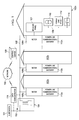
- the transmit path of a coupling circuit includes first amplifier 600 , first capacitor 605 , and first transformer 610 before splitting into three sub-circuits, one for each of three phases. Particularly, a single shared transformer 610 may be used for all three phases.
- transient voltage suppressors 615 a - c are coupled to a corresponding line interface coupling circuit, these line interface coupling circuits including capacitors 620 a - c , inductors 625 a - c , and resistors 630 a - c .
- first phase 635 a , second phase 635 b , and third phase 635 c are each referenced with respect to a same neutral wire 690 .
- capacitors 620 a - c , inductors 625 a - c , and resistors 630 a - c may implement high-pass filters configured to reduce interference from the AC frequency of the power grid (i.e., approximately 50 or 60 Hz). It should be noted that, generally speaking, any number of PLC devices, modems, meters, appliances, etc. may be coupled to any of phases 635 a - c.
- each of three capacitors 645 a - c is coupled to a respective line interface coupling circuit for each phase.
- These three capacitors 645 a - c are coupled to inductor 650 , which is coupled to resistor 655 , and which in turn is coupled to second transformer 660 .
- Second transformer 660 is coupled to resistor 665 , capacitor 670 , and inductor 675 .
- Inductor 675 and DC power source 685 are coupled to the inputs of second amplifier 680 , which is configured to output the received PLC signals.
- capacitors 645 a - c , inductor 650 , resistor 655 , transformer 660 , resistor 665 , capacitor 670 , and inductor 675 from a filter network that implements a band-pass filter.
- a PLC device may operate in either a transmitting mode or in receiving mode at a given time. Accordingly, transmitting amplifier 600 may be disabled into a high-impedance state during receiving mode. Also during reception of PLC signals, capacitors 645 a - c may linearly combine all signals in each of the three phases, and sum those signals together coming in through the high-impedance network of the receiver side or path. In some cases, the value of each of a capacitors 645 a - c may be a third of the value of capacitor 545 in FIG. 5 . More generally, the value of each such capacitor may be 1/n of the value of a single capacitor shown in FIG. 5 , where n is the number of phases in the transmit side or path.
- the band-pass filter in the receiver path may be dynamically adjustable or configurable to select a frequency band corresponding to a particular frequency of operation of the PLC device.
- the PLC device upon powering up in the PLC network, may be assigned a particular frequency of operation, including, for example, a specific frequency (or range of frequencies) at which it may expect to receive PLC communication signals.
- the adjustable band-pass filter may be configured to allow the selected frequenc(ies) to reach amplifier 680 .
- the coupling circuit of FIG. 6 uses a single transformer in its transmit path, thus occupying a smaller footprint in a PCB within the PLC device.
- transformer 660 in the receive path may be physically smaller than transformer 610 , thus providing additional space savings.
- FIG. 7 shows the transmit side of the circuit shown in FIG. 6 with certain modifications.
- the coupling circuit includes a plurality of high-voltage switches 700 a - c , each of switches 700 a - c coupled between transformer 610 and a corresponding one of the plurality of line interface coupling circuits in phases 635 a - c .
- high-voltage switches 700 a - c may be configured such that, in response to an indication that the circuit is operating in a particular transmitting mode, at least one of high-voltage switches (e.g., 700 a ) is open.
- Examples of transmitting modes may include a broadcasting mode (e.g., transmission of a PLC signal through all phases of the grid), a multicasting mode (e.g., transmission of a PLC signal through a subset of all phases of the grid and/or to a specific group of PLC devices in the PLC network), and/or a unicasting mode (e.g., transmission of a PLC signal through a single phase and/or to a specifically addressed PLC device).
- a broadcasting mode e.g., transmission of a PLC signal through all phases of the grid
- a multicasting mode e.g., transmission of a PLC signal through a subset of all phases of the grid and/or to a specific group of PLC devices in the PLC network
- a unicasting mode e.g., transmission of a PLC signal through a single phase and/or to a specifically addressed PLC device.
- the circuit if the circuit is operating in broadcast mode, all of high-voltage switches 700 a - c may be closed so that the PLC signal transmitted by the PLC device may reach all of phases 635 a - c . If, on the other hand, the circuit is operating in multicast mode, one or two (but not all three) of high-voltage switches 700 a - c may be closed so that the PLC signal may be transmitted through the relevant phases. Moreover, if the circuit is operating in unicast mode, a single one of high-voltage switches 700 a - c may be closed so that the PLC signal may be transmitted through a single phase. In this manner, the impedance of the coupling circuit may be further controlled during a transmission operation.
- high-voltage switches 700 a - c may be configured in response to an indication that the circuit is operating in a particular receiving mode. Again, the number of high-voltage switches that may be open or closed during reception may depend upon whether the PLC device is expecting to receive signals in a broadcast, multicast, or unicast modes. In this case, however, if the PLC device is set to expect to receive a PLC signal through all of its phases (e.g., in broadcast mode), only one 700 a - c may be closed, thus further increasing the impedance of the receive path.
- switches 700 a - c may be closed. If the device expects to receive the PLC signal through a particular subgroup of phases (e.g., in multicast mode), only those among switches 700 a - c corresponding to the device's expectations may be closed, and if the device is configured to receive the PLC signal through a single phase (e.g., in unicast mode), only the relevant one among switches 700 a - c may be closed. As such the impedance of the coupling circuit may be also be controlled during a reception operation.
- a particular subgroup of phases e.g., in multicast mode
- the modules shown in FIGS. 2-4 may represent sets of software routines, logic functions, and/or data structures that are configured to perform specified operations. Although these modules may be distinct logical blocks, in other embodiments at least some of the operations performed by these modules may be combined in to fewer blocks. Conversely, any given one of the modules shown in FIGS. 2-4 may be implemented such that its operations are divided among two or more logical blocks. Moreover, although shown with a particular configuration, in other embodiments these various modules may be rearranged in other suitable ways.
Landscapes
- Engineering & Computer Science (AREA)
- Power Engineering (AREA)
- Computer Networks & Wireless Communication (AREA)
- Signal Processing (AREA)
- Cable Transmission Systems, Equalization Of Radio And Reduction Of Echo (AREA)
- Telephonic Communication Services (AREA)
Priority Applications (5)
| Application Number | Priority Date | Filing Date | Title |
|---|---|---|---|
| US13/229,041 US9276638B2 (en) | 2010-09-22 | 2011-09-09 | Coupling circuits for power line communication devices |
| CN201180045802.9A CN103119853B (zh) | 2010-09-22 | 2011-09-22 | 用于电力线通信装置的耦合电路 |
| JP2013530315A JP5875588B2 (ja) | 2010-09-22 | 2011-09-22 | 電力ライン通信デバイスのための結合回路 |
| PCT/US2011/052777 WO2012040476A1 (en) | 2010-09-22 | 2011-09-22 | Coupling circuits for power line communication devices |
| US15/005,099 US9787362B2 (en) | 2010-09-22 | 2016-01-25 | Transmitter path for power line communication devices |
Applications Claiming Priority (2)
| Application Number | Priority Date | Filing Date | Title |
|---|---|---|---|
| US38533910P | 2010-09-22 | 2010-09-22 | |
| US13/229,041 US9276638B2 (en) | 2010-09-22 | 2011-09-09 | Coupling circuits for power line communication devices |
Related Child Applications (1)
| Application Number | Title | Priority Date | Filing Date |
|---|---|---|---|
| US15/005,099 Continuation US9787362B2 (en) | 2010-09-22 | 2016-01-25 | Transmitter path for power line communication devices |
Publications (2)
| Publication Number | Publication Date |
|---|---|
| US20120068784A1 US20120068784A1 (en) | 2012-03-22 |
| US9276638B2 true US9276638B2 (en) | 2016-03-01 |
Family
ID=45817212
Family Applications (2)
| Application Number | Title | Priority Date | Filing Date |
|---|---|---|---|
| US13/229,041 Active 2034-10-10 US9276638B2 (en) | 2010-09-22 | 2011-09-09 | Coupling circuits for power line communication devices |
| US15/005,099 Active 2031-09-21 US9787362B2 (en) | 2010-09-22 | 2016-01-25 | Transmitter path for power line communication devices |
Family Applications After (1)
| Application Number | Title | Priority Date | Filing Date |
|---|---|---|---|
| US15/005,099 Active 2031-09-21 US9787362B2 (en) | 2010-09-22 | 2016-01-25 | Transmitter path for power line communication devices |
Country Status (4)
| Country | Link |
|---|---|
| US (2) | US9276638B2 (enExample) |
| JP (1) | JP5875588B2 (enExample) |
| CN (1) | CN103119853B (enExample) |
| WO (1) | WO2012040476A1 (enExample) |
Families Citing this family (22)
| Publication number | Priority date | Publication date | Assignee | Title |
|---|---|---|---|---|
| US20120265355A1 (en) | 2011-04-15 | 2012-10-18 | Power Tagging Technologies, Inc. | System and method for single and multizonal optimization of utility services delivery and utilization |
| WO2013009420A1 (en) | 2011-06-09 | 2013-01-17 | Power Tagging Technologies, Inc. | System and method for grid based cyber security |
| US9350423B2 (en) * | 2011-06-30 | 2016-05-24 | The Boeing Company | Methods and system for increasing data transmission rates across a three-phase power system |
| WO2013020053A1 (en) | 2011-08-03 | 2013-02-07 | Power Tagging Technologies, Inc. | System and methods for synchronizing edge devices on channels without carrier sense |
| US20140111375A1 (en) * | 2012-10-19 | 2014-04-24 | Qualcomm Incorporated | Gnss fine-time assistance over rtt-capable wireless networks |
| US10097240B2 (en) * | 2013-02-19 | 2018-10-09 | Astrolink International, Llc | System and method for inferring schematic and topological properties of an electrical distribution grid |
| CN105453448A (zh) | 2013-06-13 | 2016-03-30 | 艾斯通林克国际有限责任公司 | 推断为发射机提供电力的馈电线和相位 |
| EP3008478A4 (en) | 2013-06-13 | 2017-03-01 | Astrolink International LLC | Non-technical losses in a power distribution grid |
| US10348418B1 (en) * | 2014-07-22 | 2019-07-09 | Esker Technologies, LLC | Transient and spurious signal filter |
| US10079765B2 (en) | 2014-10-30 | 2018-09-18 | Astrolink International Llc | System and methods for assigning slots and resolving slot conflicts in an electrical distribution grid |
| US9853498B2 (en) | 2014-10-30 | 2017-12-26 | Astrolink International Llc | System, method, and apparatus for grid location |
| WO2016145560A1 (zh) * | 2015-03-13 | 2016-09-22 | 华为技术有限公司 | 一种网关侧电力线通信plc子系统、网关及耦合解耦器 |
| RU2714858C2 (ru) | 2015-04-17 | 2020-02-19 | Ландис+Гир АГ | Счетчик электроэнергии и модуль адаптера для него |
| US10417143B2 (en) | 2015-10-08 | 2019-09-17 | Esker Technologies, LLC | Apparatus and method for sending power over synchronous serial communication wiring |
| US10128906B2 (en) | 2016-07-11 | 2018-11-13 | Esker Technologies, LLC | Power line signal coupler |
| US10560154B2 (en) | 2016-07-11 | 2020-02-11 | Esker Technologies, LLC | Power line signal coupler |
| CN106160086B (zh) * | 2016-07-14 | 2019-10-15 | 深圳市禾家欢科技有限公司 | 一种无线充电输出装置 |
| CN109981140B (zh) * | 2019-04-26 | 2024-05-07 | 深圳芯珑电子技术有限公司 | 一种电力载波通信模块功率灵敏度测试系统 |
| US11323435B2 (en) | 2019-05-08 | 2022-05-03 | The Boeing Company | Method and apparatus for advanced security systems over a power line connection |
| US11037427B2 (en) * | 2019-08-14 | 2021-06-15 | Schneider Electric USA, Inc. | Load center position-based addressing |
| CN111601414A (zh) * | 2020-04-22 | 2020-08-28 | 上海亚明照明有限公司 | Plc智能灯控方法、plc网关、plc灯具、及系统 |
| CN112365700A (zh) * | 2020-10-27 | 2021-02-12 | 广东电网有限责任公司广州供电局 | 一种低压集抄方法和装置 |
Citations (2)
| Publication number | Priority date | Publication date | Assignee | Title |
|---|---|---|---|---|
| US20060165054A1 (en) | 2005-01-21 | 2006-07-27 | Ryuichi Iwamura | Power line network bridge |
| US20110200076A1 (en) * | 2010-02-18 | 2011-08-18 | Telefonaktiebolaget Lm Ericsson (Publ) | Rf clock generator with spurious tone cancellation |
Family Cites Families (10)
| Publication number | Priority date | Publication date | Assignee | Title |
|---|---|---|---|---|
| US4473817A (en) * | 1982-04-13 | 1984-09-25 | Rockwell International Corporation | Coupling power line communications signals around distribution transformers |
| JP3460186B2 (ja) * | 1998-07-07 | 2003-10-27 | 東光電気株式会社 | 配電線路制御システム |
| JP2003143044A (ja) * | 2001-10-31 | 2003-05-16 | Matsushita Electric Ind Co Ltd | 2線式電源多重通信システム、そのマスター装置及び2線式電源多重通信方法 |
| KR100429584B1 (ko) * | 2002-04-12 | 2004-05-03 | 주식회사 플레넷 | 전력선 통신을 위한 아날로그 프론트엔드 장치 및 전력선커플러 |
| JP4543817B2 (ja) * | 2004-08-13 | 2010-09-15 | パナソニック電工株式会社 | 電力線搬送通信装置 |
| JP2007104205A (ja) * | 2005-10-03 | 2007-04-19 | Alps Electric Co Ltd | 電力線通信装置 |
| JP2007158539A (ja) * | 2005-12-01 | 2007-06-21 | Sumitomo Electric Ind Ltd | 電力線通信装置、電力線通信方法、及び電力線通信システム |
| US7319280B1 (en) * | 2007-04-24 | 2008-01-15 | Telkonet, Inc. | Power line coupler adapted for use with multiple communication systems using different frequency spectra |
| PL2009807T3 (pl) * | 2007-06-26 | 2010-09-30 | Eandis | System komunikacji za pośrednictwem elektroenergetycznej linii dystrybucyjnej |
| KR100901196B1 (ko) * | 2007-10-17 | 2009-07-09 | 주식회사 플레넷 | 저전력 전력선통신모뎀을 위한 ac 커플러 |
-
2011
- 2011-09-09 US US13/229,041 patent/US9276638B2/en active Active
- 2011-09-22 CN CN201180045802.9A patent/CN103119853B/zh active Active
- 2011-09-22 WO PCT/US2011/052777 patent/WO2012040476A1/en not_active Ceased
- 2011-09-22 JP JP2013530315A patent/JP5875588B2/ja active Active
-
2016
- 2016-01-25 US US15/005,099 patent/US9787362B2/en active Active
Patent Citations (2)
| Publication number | Priority date | Publication date | Assignee | Title |
|---|---|---|---|---|
| US20060165054A1 (en) | 2005-01-21 | 2006-07-27 | Ryuichi Iwamura | Power line network bridge |
| US20110200076A1 (en) * | 2010-02-18 | 2011-08-18 | Telefonaktiebolaget Lm Ericsson (Publ) | Rf clock generator with spurious tone cancellation |
Also Published As
| Publication number | Publication date |
|---|---|
| JP5875588B2 (ja) | 2016-03-02 |
| US20160142103A1 (en) | 2016-05-19 |
| JP2013542651A (ja) | 2013-11-21 |
| US20120068784A1 (en) | 2012-03-22 |
| CN103119853A (zh) | 2013-05-22 |
| CN103119853B (zh) | 2014-12-03 |
| WO2012040476A1 (en) | 2012-03-29 |
| US9787362B2 (en) | 2017-10-10 |
Similar Documents
| Publication | Publication Date | Title |
|---|---|---|
| US9787362B2 (en) | Transmitter path for power line communication devices | |
| US11831358B2 (en) | Coexistence primitives in power line communication networks | |
| US12132530B2 (en) | Long preamble and duty cycle based coexistence mechanism for power line communication (PLC) networks | |
| US10277276B2 (en) | Systems and methods for implementing application profiles and device classes in power line communication (PLC) environments | |
| US20150171922A1 (en) | Channel Selection in Power Line Communications | |
| US9350424B2 (en) | Coexistence method by requesting access to the channel | |
| US20130301649A1 (en) | CSMA/CA for Channels in Power Line Communication (PLC) Networks | |
| US20150180680A1 (en) | Overlapping priority contention windows power line communications networks | |
| US20120076211A1 (en) | Systems and Methods for Facilitating Power Line Communications | |
| US9503158B2 (en) | Adaptive sub-band algorithm for point-to-point communication in PLC networks | |
| US8964786B2 (en) | Communications in beacon-enabled networks |
Legal Events
| Date | Code | Title | Description |
|---|---|---|---|
| AS | Assignment |
Owner name: TEXAS INSTRUMENTS INC., TEXAS Free format text: ASSIGNMENT OF ASSIGNORS INTEREST;ASSIGNORS:VARADARAJAN, BADRI;MULLINS, EDWARD;REEL/FRAME:026891/0312 Effective date: 20110909 |
|
| STCF | Information on status: patent grant |
Free format text: PATENTED CASE |
|
| MAFP | Maintenance fee payment |
Free format text: PAYMENT OF MAINTENANCE FEE, 4TH YEAR, LARGE ENTITY (ORIGINAL EVENT CODE: M1551); ENTITY STATUS OF PATENT OWNER: LARGE ENTITY Year of fee payment: 4 |
|
| MAFP | Maintenance fee payment |
Free format text: PAYMENT OF MAINTENANCE FEE, 8TH YEAR, LARGE ENTITY (ORIGINAL EVENT CODE: M1552); ENTITY STATUS OF PATENT OWNER: LARGE ENTITY Year of fee payment: 8 |