US925893A - Window-fixture. - Google Patents
Window-fixture. Download PDFInfo
- Publication number
- US925893A US925893A US44430908A US1908444309A US925893A US 925893 A US925893 A US 925893A US 44430908 A US44430908 A US 44430908A US 1908444309 A US1908444309 A US 1908444309A US 925893 A US925893 A US 925893A
- Authority
- US
- United States
- Prior art keywords
- window
- fixture
- extending
- vertical member
- bearing
- Prior art date
- Legal status (The legal status is an assumption and is not a legal conclusion. Google has not performed a legal analysis and makes no representation as to the accuracy of the status listed.)
- Expired - Lifetime
Links
- 241001229135 Nassa Species 0.000 description 1
- 239000011324 bead Substances 0.000 description 1
- 238000010276 construction Methods 0.000 description 1
- 238000004519 manufacturing process Methods 0.000 description 1
Images
Classifications
-
- A—HUMAN NECESSITIES
- A47—FURNITURE; DOMESTIC ARTICLES OR APPLIANCES; COFFEE MILLS; SPICE MILLS; SUCTION CLEANERS IN GENERAL
- A47H—FURNISHINGS FOR WINDOWS OR DOORS
- A47H1/00—Curtain suspension devices
- A47H1/10—Means for mounting curtain rods or rails
- A47H1/13—Brackets or adjustable mountings for both roller blinds and drawable curtains
Definitions
- the object of-the invention is to provide a new and improved window fixture, con1bining means for supporting or holding a curtain pole, shade roller and blind, the fixture being simple and durable in construction, cheap to manufacture and easily applied'to the window casing without the use of nails, screws or similar fastening devices.
- the invention consists of'novel feature and parts and combinations of the same,
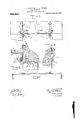
- Figure 1 is a reduced front elevation of the improvement as applied;
- Fig. 2 is a cross section of the same on the line 2-2 of Fig. 1;
- Fig. 3 is'a sectional plan view of the same'on the line 33 of Fig. 2;
- Fig. 4 is a plan view of the shade roller supporting bar.
- the window fixture consists essentially of from a single piece of spring wire bent to form a vertical member B, adapted to rest on the front face of the topcross bar C of the window casing, as plainly indicated in Figs. 1 and. 2.
- the upper end of the vertical member B term'inate'sin a transversely-extending hook D, adapted to hook onto the top ofthe cross bar C (see Fig.- 2), to support each bracket on the top cross bar.
- Fromthe vertical member B extend forwardly the twisted portions E terminating in a bearing F for supporting the curtainpole G the desired distance from the window casing, as will be understood by reference to Figs. 1 and 2.
- each vertical member 1)- terminates in an open bearing H for supporting the bar I made i111 sections adjustable one on the other, the ends of-the b: r I being provided with .the usual shaderol brackets'J for receiving the pintles of an ordinary spring shade roller K.
- the shade roller sup )orting bar I can be adjusted in the direction of its length to suit a shade roller of an ordinary size, it being understood that after the sections of the support are adjusted they are fastened in place by suitable set screws I, as indicated in Fig. 4.
- Each of the bearings H terminate in a transversely-extending spring member L adapted to rest against theinner face of the corresponding side C of the Window casing and also against the under side of the cross bar C, so as to securely hold the hook D in engagement with the top of the crossbar C, as indicated in Fig. 2.
- the spring member L terminates at its inner end in a foot N, adapted to abut against the stop bead C of the window casing, so as tolimit. the inward movement of the spring member. L, and to insure a rigid attachment of each bracket on the window casing.
- the spring member L of each bracket A is provided with a sidewise extending bent portion 0 the reception of the pintles Q, of a blind roller Q, extending within the opening of the window casing, as plainly indicated in the drawings.
- the bent portion 0 the ends of the pintles Q do not come in contact with the inner faces of the sides C and hence are not liable to mar the same.
- each bracket A is formed of a single piece of wire andforms supports for the curtain pole, the
- each bracket A is securely held in place without the use of screws, nails or similar fastening devices.
- a window fixture comprising a pair of brackets, each made .of a'single piece of spring wire bent to form a vertical member provided at its upper end with a hook for engagement with the top of the cross bar of the window casing, a curtain pole support" formed by twisting the wire and extending the same transversely from the said vertical.
- the said spring member having a sidewise bent portion between the ends and a bearing for a blind roller formed in the said sidewise bent per-- tion, and a shade roller supporting bar fitting into the said second open bearings of the two brackets.
- a window fixture comprising a pair of brackets, each made or a single piece of spring wire bent to form a vertical member provided at its upper end with a hook for engagement with the top of the cross bar of the window .casing, a curtain pole support formed by twisting the wire and extending the same transversely from the said vertical member, the outer portion of the said support being formed into an open bearing for the curtain pole, a second open bearing at the lower end of the said vertical member, and a spring member extending transversely from the said second bearing and adapted to engage the under side of the said top cross bar, the said spring member having asidewise bent portion between its ends and a bearing for a blind roller formed in the said sidewise bent portion, a shade roller supporting bar'fitting into the said second open bearings of the two brackets, the said shade roller supporting bar being made in' sections slidably mounted one on the other, and means for securing the sections in place after the adjustment is made.
- a window fixture comprising a pair of brackets formed of a single plece of Wire bent to form a vertical member having at its upper end a hook, and at its center a laterally extending curtain pole support, the
Landscapes
- Curtains And Furnishings For Windows Or Doors (AREA)
Description
A. P. GIROUARD & P. A. PERRON. wmvow FIXTURE.
APPLICATION FILED JULY 20, 1998.
Patented June 22, 1909.
INVENTOHS filderzc]? Gimme? arclzrz and J5. P21 To A 77'OHN E Y8 TEE-1 WITNESSES 'AL'DERio'F. 'GIROUARD, or LnoMINsrER, AND FERDINAND A.
. nassa'onusnrrs.
as PATENT orries.
PERRON, or FITCHBURG,
WINDOW-FIXTURE No. 926,893. Specification of Letters Patent.
Patented June 22, 1909.
Application filed July 20, 1908. Serial No. 444,309.
United States, and residents, respectively, of
Leominster, in the county of Worcester and State of Massachusetts, and of Fitchburg, in
the county of W'orces ter and State of Massachusetts, have invented a new and Improved \VindOw-Fixture, of which the following is a full, clear, and exact description.
The object of-the invention is to provide a new and improved window fixture, con1bining means for supporting or holding a curtain pole, shade roller and blind, the fixture being simple and durable in construction, cheap to manufacture and easily applied'to the window casing without the use of nails, screws or similar fastening devices. The invention consists of'novel feature and parts and combinations of the same,
, which will be more fully described herein- P brackets A, A, each' made after and then pointed out in the claims. ,A practical embodiment of the invention is represented in the accompanying drawings forming a part of this specification, in which similar characters of refcrenceqindicate corresponding parts in all the views.
Figure 1 is a reduced front elevation of the improvement as applied; Fig. 2 is a cross section of the same on the line 2-2 of Fig. 1; Fig. 3 is'a sectional plan view of the same'on the line 33 of Fig. 2; and Fig. 4 is a plan view of the shade roller supporting bar.
The window fixture consists essentially of from a single piece of spring wire bent to form a vertical member B, adapted to rest on the front face of the topcross bar C of the window casing, as plainly indicated in Figs. 1 and. 2. The upper end of the vertical member B term'inate'sin a transversely-extending hook D, adapted to hook onto the top ofthe cross bar C (see Fig.- 2), to support each bracket on the top cross bar. ,Fromthe vertical member B extend forwardly the twisted portions E terminating in a bearing F for supporting the curtainpole G the desired distance from the window casing, as will be understood by reference to Figs. 1 and 2. Thelower end of each vertical member 1)- terminates in an open bearing H for supporting the bar I made i111 sections adjustable one on the other, the ends of-the b: r I being provided with .the usual shaderol brackets'J for receiving the pintles of an ordinary spring shade roller K. By the arrangement described, the shade roller sup )orting bar I can be adjusted in the direction of its length to suit a shade roller of an ordinary size, it being understood that after the sections of the support are adjusted they are fastened in place by suitable set screws I, as indicated in Fig. 4.
Each of the bearings H terminate in a transversely-extending spring member L adapted to rest against theinner face of the corresponding side C of the Window casing and also against the under side of the cross bar C, so as to securely hold the hook D in engagement with the top of the crossbar C, as indicated in Fig. 2. The spring member L terminates at its inner end in a foot N, adapted to abut against the stop bead C of the window casing, so as tolimit. the inward movement of the spring member. L, and to insure a rigid attachment of each bracket on the window casing. "The spring member L of each bracket A is provided with a sidewise extending bent portion 0 the reception of the pintles Q, of a blind roller Q, extending within the opening of the window casing, as plainly indicated in the drawings. By having the bent portion 0, the ends of the pintles Q do not come in contact with the inner faces of the sides C and hence are not liable to mar the same.
Now by the arrangement described, each bracket A is formed of a single piece of wire andforms supports for the curtain pole, the
shade roller and a blind roller, and each bracket A is securely held in place without the use of screws, nails or similar fastening devices.
Having thus described our invention, we claim as new and desire to secure by Letters Patent;
1. A window fixture, comprising a pair of brackets, each made .of a'single piece of spring wire bent to form a vertical member provided at its upper end with a hook for engagement with the top of the cross bar of the window casing, a curtain pole support" formed by twisting the wire and extending the same transversely from the said vertical.
member, the outer portion of the said support being formed into an open bearing for the *curtain pole, a. second open hearing at the lower end of the said vertical'mcinber,
and a spring extending from the said second bearing and adapted to engage the under side of the said top cross bar, the said spring member having a sidewise bent portion between the ends and a bearing for a blind roller formed in the said sidewise bent per-- tion, and a shade roller supporting bar fitting into the said second open bearings of the two brackets.
2. A window fixture, comprising a pair of brackets, each made or a single piece of spring wire bent to form a vertical member provided at its upper end with a hook for engagement with the top of the cross bar of the window .casing, a curtain pole support formed by twisting the wire and extending the same transversely from the said vertical member, the outer portion of the said support being formed into an open bearing for the curtain pole, a second open bearing at the lower end of the said vertical member, and a spring member extending transversely from the said second bearing and adapted to engage the under side of the said top cross bar, the said spring member having asidewise bent portion between its ends and a bearing for a blind roller formed in the said sidewise bent portion, a shade roller supporting bar'fitting into the said second open bearings of the two brackets, the said shade roller supporting bar being made in' sections slidably mounted one on the other, and means for securing the sections in place after the adjustment is made.
3. A window fixture comprising a pair of brackets formed of a single plece of Wire bent to form a vertical member having at its upper end a hook, and at its center a laterally extending curtain pole support, the
wire at the bottom of the vertical member
Priority Applications (1)
| Application Number | Priority Date | Filing Date | Title |
|---|---|---|---|
| US44430908A US925893A (en) | 1908-07-20 | 1908-07-20 | Window-fixture. |
Applications Claiming Priority (1)
| Application Number | Priority Date | Filing Date | Title |
|---|---|---|---|
| US44430908A US925893A (en) | 1908-07-20 | 1908-07-20 | Window-fixture. |
Publications (1)
| Publication Number | Publication Date |
|---|---|
| US925893A true US925893A (en) | 1909-06-22 |
Family
ID=2994321
Family Applications (1)
| Application Number | Title | Priority Date | Filing Date |
|---|---|---|---|
| US44430908A Expired - Lifetime US925893A (en) | 1908-07-20 | 1908-07-20 | Window-fixture. |
Country Status (1)
| Country | Link |
|---|---|
| US (1) | US925893A (en) |
-
1908
- 1908-07-20 US US44430908A patent/US925893A/en not_active Expired - Lifetime
Similar Documents
| Publication | Publication Date | Title |
|---|---|---|
| US1196936A (en) | Support for picture-frames. | |
| US925893A (en) | Window-fixture. | |
| US1103491A (en) | Picture-hanger. | |
| US571184A (en) | Bamfoed | |
| US624482A (en) | Window-fixture | |
| US1017574A (en) | Curtain-fixture. | |
| US803454A (en) | Window shade and curtain bracket. | |
| US743712A (en) | Curtain-fixture. | |
| US1231923A (en) | Curtain-pole bracket. | |
| US598409A (en) | Roller-shade fixture | |
| US1035626A (en) | Combination shade and curtain hanger. | |
| US124131A (en) | Improvement in curtain-fixtures | |
| US789897A (en) | Combination shade and curtain bracket. | |
| US752397A (en) | Curtain-roll support | |
| US1168814A (en) | Adjustable curtain-pole and shade hanger. | |
| US825773A (en) | Hanger. | |
| US771179A (en) | Window-shade fixture. | |
| US758098A (en) | Combined shade-roller and curtain-pole holder. | |
| US1002838A (en) | Curtain and shade support. | |
| US859339A (en) | Window-shade holder. | |
| US1095311A (en) | Combined shade and curtain holder. | |
| US766589A (en) | Window curtain and shade adjuster. | |
| US1112160A (en) | Curtain-pole bracket. | |
| US1193403A (en) | Charles s | |
| US388151A (en) | Curtain-pole bracket |