US9243916B2 - Observability-constrained vision-aided inertial navigation - Google Patents
Observability-constrained vision-aided inertial navigation Download PDFInfo
- Publication number
- US9243916B2 US9243916B2 US14/186,597 US201414186597A US9243916B2 US 9243916 B2 US9243916 B2 US 9243916B2 US 201414186597 A US201414186597 A US 201414186597A US 9243916 B2 US9243916 B2 US 9243916B2
- Authority
- US
- United States
- Prior art keywords
- vision
- imu
- navigation system
- inertial navigation
- sensing device
- Prior art date
- Legal status (The legal status is an assumption and is not a legal conclusion. Google has not performed a legal analysis and makes no representation as to the accuracy of the status listed.)
- Active
Links
Images
Classifications
-
- G—PHYSICS
- G01—MEASURING; TESTING
- G01C—MEASURING DISTANCES, LEVELS OR BEARINGS; SURVEYING; NAVIGATION; GYROSCOPIC INSTRUMENTS; PHOTOGRAMMETRY OR VIDEOGRAMMETRY
- G01C21/00—Navigation; Navigational instruments not provided for in groups G01C1/00 - G01C19/00
- G01C21/10—Navigation; Navigational instruments not provided for in groups G01C1/00 - G01C19/00 by using measurements of speed or acceleration
- G01C21/12—Navigation; Navigational instruments not provided for in groups G01C1/00 - G01C19/00 by using measurements of speed or acceleration executed aboard the object being navigated; Dead reckoning
- G01C21/16—Navigation; Navigational instruments not provided for in groups G01C1/00 - G01C19/00 by using measurements of speed or acceleration executed aboard the object being navigated; Dead reckoning by integrating acceleration or speed, i.e. inertial navigation
- G01C21/165—Navigation; Navigational instruments not provided for in groups G01C1/00 - G01C19/00 by using measurements of speed or acceleration executed aboard the object being navigated; Dead reckoning by integrating acceleration or speed, i.e. inertial navigation combined with non-inertial navigation instruments
-
- B—PERFORMING OPERATIONS; TRANSPORTING
- B25—HAND TOOLS; PORTABLE POWER-DRIVEN TOOLS; MANIPULATORS
- B25J—MANIPULATORS; CHAMBERS PROVIDED WITH MANIPULATION DEVICES
- B25J5/00—Manipulators mounted on wheels or on carriages
-
- B—PERFORMING OPERATIONS; TRANSPORTING
- B25—HAND TOOLS; PORTABLE POWER-DRIVEN TOOLS; MANIPULATORS
- B25J—MANIPULATORS; CHAMBERS PROVIDED WITH MANIPULATION DEVICES
- B25J9/00—Program-controlled manipulators
- B25J9/16—Program controls
- B25J9/1656—Program controls characterised by programming, planning systems for manipulators
- B25J9/1664—Program controls characterised by programming, planning systems for manipulators characterised by motion, path, trajectory planning
-
- B—PERFORMING OPERATIONS; TRANSPORTING
- B25—HAND TOOLS; PORTABLE POWER-DRIVEN TOOLS; MANIPULATORS
- B25J—MANIPULATORS; CHAMBERS PROVIDED WITH MANIPULATION DEVICES
- B25J9/00—Program-controlled manipulators
- B25J9/16—Program controls
- B25J9/1694—Program controls characterised by use of sensors other than normal servo-feedback from position, speed or acceleration sensors, perception control, multi-sensor controlled systems, sensor fusion
- B25J9/1697—Vision controlled systems
-
- G—PHYSICS
- G01—MEASURING; TESTING
- G01C—MEASURING DISTANCES, LEVELS OR BEARINGS; SURVEYING; NAVIGATION; GYROSCOPIC INSTRUMENTS; PHOTOGRAMMETRY OR VIDEOGRAMMETRY
- G01C21/00—Navigation; Navigational instruments not provided for in groups G01C1/00 - G01C19/00
- G01C21/10—Navigation; Navigational instruments not provided for in groups G01C1/00 - G01C19/00 by using measurements of speed or acceleration
- G01C21/12—Navigation; Navigational instruments not provided for in groups G01C1/00 - G01C19/00 by using measurements of speed or acceleration executed aboard the object being navigated; Dead reckoning
- G01C21/16—Navigation; Navigational instruments not provided for in groups G01C1/00 - G01C19/00 by using measurements of speed or acceleration executed aboard the object being navigated; Dead reckoning by integrating acceleration or speed, i.e. inertial navigation
- G01C21/165—Navigation; Navigational instruments not provided for in groups G01C1/00 - G01C19/00 by using measurements of speed or acceleration executed aboard the object being navigated; Dead reckoning by integrating acceleration or speed, i.e. inertial navigation combined with non-inertial navigation instruments
- G01C21/1652—Navigation; Navigational instruments not provided for in groups G01C1/00 - G01C19/00 by using measurements of speed or acceleration executed aboard the object being navigated; Dead reckoning by integrating acceleration or speed, i.e. inertial navigation combined with non-inertial navigation instruments with ranging devices, e.g. LIDAR or RADAR
-
- G—PHYSICS
- G01—MEASURING; TESTING
- G01C—MEASURING DISTANCES, LEVELS OR BEARINGS; SURVEYING; NAVIGATION; GYROSCOPIC INSTRUMENTS; PHOTOGRAMMETRY OR VIDEOGRAMMETRY
- G01C21/00—Navigation; Navigational instruments not provided for in groups G01C1/00 - G01C19/00
- G01C21/10—Navigation; Navigational instruments not provided for in groups G01C1/00 - G01C19/00 by using measurements of speed or acceleration
- G01C21/12—Navigation; Navigational instruments not provided for in groups G01C1/00 - G01C19/00 by using measurements of speed or acceleration executed aboard the object being navigated; Dead reckoning
- G01C21/16—Navigation; Navigational instruments not provided for in groups G01C1/00 - G01C19/00 by using measurements of speed or acceleration executed aboard the object being navigated; Dead reckoning by integrating acceleration or speed, i.e. inertial navigation
- G01C21/165—Navigation; Navigational instruments not provided for in groups G01C1/00 - G01C19/00 by using measurements of speed or acceleration executed aboard the object being navigated; Dead reckoning by integrating acceleration or speed, i.e. inertial navigation combined with non-inertial navigation instruments
- G01C21/1656—Navigation; Navigational instruments not provided for in groups G01C1/00 - G01C19/00 by using measurements of speed or acceleration executed aboard the object being navigated; Dead reckoning by integrating acceleration or speed, i.e. inertial navigation combined with non-inertial navigation instruments with passive imaging devices, e.g. cameras
-
- G—PHYSICS
- G01—MEASURING; TESTING
- G01C—MEASURING DISTANCES, LEVELS OR BEARINGS; SURVEYING; NAVIGATION; GYROSCOPIC INSTRUMENTS; PHOTOGRAMMETRY OR VIDEOGRAMMETRY
- G01C21/00—Navigation; Navigational instruments not provided for in groups G01C1/00 - G01C19/00
- G01C21/10—Navigation; Navigational instruments not provided for in groups G01C1/00 - G01C19/00 by using measurements of speed or acceleration
- G01C21/12—Navigation; Navigational instruments not provided for in groups G01C1/00 - G01C19/00 by using measurements of speed or acceleration executed aboard the object being navigated; Dead reckoning
- G01C21/16—Navigation; Navigational instruments not provided for in groups G01C1/00 - G01C19/00 by using measurements of speed or acceleration executed aboard the object being navigated; Dead reckoning by integrating acceleration or speed, i.e. inertial navigation
- G01C21/183—Compensation of inertial measurements, e.g. for temperature effects
- G01C21/185—Compensation of inertial measurements, e.g. for temperature effects for gravity
-
- G—PHYSICS
- G01—MEASURING; TESTING
- G01C—MEASURING DISTANCES, LEVELS OR BEARINGS; SURVEYING; NAVIGATION; GYROSCOPIC INSTRUMENTS; PHOTOGRAMMETRY OR VIDEOGRAMMETRY
- G01C21/00—Navigation; Navigational instruments not provided for in groups G01C1/00 - G01C19/00
- G01C21/10—Navigation; Navigational instruments not provided for in groups G01C1/00 - G01C19/00 by using measurements of speed or acceleration
- G01C21/12—Navigation; Navigational instruments not provided for in groups G01C1/00 - G01C19/00 by using measurements of speed or acceleration executed aboard the object being navigated; Dead reckoning
- G01C21/16—Navigation; Navigational instruments not provided for in groups G01C1/00 - G01C19/00 by using measurements of speed or acceleration executed aboard the object being navigated; Dead reckoning by integrating acceleration or speed, i.e. inertial navigation
- G01C21/183—Compensation of inertial measurements, e.g. for temperature effects
- G01C21/188—Compensation of inertial measurements, e.g. for temperature effects for accumulated errors, e.g. by coupling inertial systems with absolute positioning systems
-
- G—PHYSICS
- G06—COMPUTING OR CALCULATING; COUNTING
- G06F—ELECTRIC DIGITAL DATA PROCESSING
- G06F3/00—Input arrangements for transferring data to be processed into a form capable of being handled by the computer; Output arrangements for transferring data from processing unit to output unit, e.g. interface arrangements
- G06F3/01—Input arrangements or combined input and output arrangements for interaction between user and computer
- G06F3/03—Arrangements for converting the position or the displacement of a member into a coded form
- G06F3/033—Pointing devices displaced or positioned by the user, e.g. mice, trackballs, pens or joysticks; Accessories therefor
- G06F3/0346—Pointing devices displaced or positioned by the user, e.g. mice, trackballs, pens or joysticks; Accessories therefor with detection of the device orientation or free movement in a three-dimensional [3D] space, e.g. 3D mice, 6-DOF [six degrees of freedom] pointers using gyroscopes, accelerometers or tilt-sensors
-
- G—PHYSICS
- G06—COMPUTING OR CALCULATING; COUNTING
- G06T—IMAGE DATA PROCESSING OR GENERATION, IN GENERAL
- G06T7/00—Image analysis
- G06T7/20—Analysis of motion
-
- G—PHYSICS
- G06—COMPUTING OR CALCULATING; COUNTING
- G06T—IMAGE DATA PROCESSING OR GENERATION, IN GENERAL
- G06T7/00—Image analysis
- G06T7/20—Analysis of motion
- G06T7/277—Analysis of motion involving stochastic approaches, e.g. using Kalman filters
-
- G—PHYSICS
- G06—COMPUTING OR CALCULATING; COUNTING
- G06T—IMAGE DATA PROCESSING OR GENERATION, IN GENERAL
- G06T7/00—Image analysis
- G06T7/70—Determining position or orientation of objects or cameras
-
- G—PHYSICS
- G06—COMPUTING OR CALCULATING; COUNTING
- G06T—IMAGE DATA PROCESSING OR GENERATION, IN GENERAL
- G06T7/00—Image analysis
- G06T7/80—Analysis of captured images to determine intrinsic or extrinsic camera parameters, i.e. camera calibration
-
- H—ELECTRICITY
- H04—ELECTRIC COMMUNICATION TECHNIQUE
- H04N—PICTORIAL COMMUNICATION, e.g. TELEVISION
- H04N13/00—Stereoscopic video systems; Multi-view video systems; Details thereof
- H04N13/20—Image signal generators
- H04N13/204—Image signal generators using stereoscopic image cameras
-
- G—PHYSICS
- G06—COMPUTING OR CALCULATING; COUNTING
- G06T—IMAGE DATA PROCESSING OR GENERATION, IN GENERAL
- G06T2207/00—Indexing scheme for image analysis or image enhancement
- G06T2207/10—Image acquisition modality
- G06T2207/10016—Video; Image sequence
- G06T2207/10021—Stereoscopic video; Stereoscopic image sequence
-
- G—PHYSICS
- G06—COMPUTING OR CALCULATING; COUNTING
- G06T—IMAGE DATA PROCESSING OR GENERATION, IN GENERAL
- G06T2207/00—Indexing scheme for image analysis or image enhancement
- G06T2207/30—Subject of image; Context of image processing
- G06T2207/30244—Camera pose
-
- Y—GENERAL TAGGING OF NEW TECHNOLOGICAL DEVELOPMENTS; GENERAL TAGGING OF CROSS-SECTIONAL TECHNOLOGIES SPANNING OVER SEVERAL SECTIONS OF THE IPC; TECHNICAL SUBJECTS COVERED BY FORMER USPC CROSS-REFERENCE ART COLLECTIONS [XRACs] AND DIGESTS
- Y10—TECHNICAL SUBJECTS COVERED BY FORMER USPC
- Y10S—TECHNICAL SUBJECTS COVERED BY FORMER USPC CROSS-REFERENCE ART COLLECTIONS [XRACs] AND DIGESTS
- Y10S901/00—Robots
- Y10S901/01—Mobile robot
-
- Y—GENERAL TAGGING OF NEW TECHNOLOGICAL DEVELOPMENTS; GENERAL TAGGING OF CROSS-SECTIONAL TECHNOLOGIES SPANNING OVER SEVERAL SECTIONS OF THE IPC; TECHNICAL SUBJECTS COVERED BY FORMER USPC CROSS-REFERENCE ART COLLECTIONS [XRACs] AND DIGESTS
- Y10—TECHNICAL SUBJECTS COVERED BY FORMER USPC
- Y10S—TECHNICAL SUBJECTS COVERED BY FORMER USPC CROSS-REFERENCE ART COLLECTIONS [XRACs] AND DIGESTS
- Y10S901/00—Robots
- Y10S901/02—Arm motion controller
- Y10S901/09—Closed loop, sensor feedback controls arm movement
Definitions
- This disclosure relates to navigation and, more particularly, to vision-aided inertial navigation.
- a Vision-aided Inertial Navigation System fuses data from a camera and an Inertial Measurement Unit (IMU) to track the six-degrees-of-freedom (d.o.f.) position and orientation (pose) of a sensing platform.
- IMU Inertial Measurement Unit
- the VINS combines complementary sensing capabilities.
- an IMU can accurately track dynamic motions over short time durations, while visual data can be used to estimate the pose displacement (up to scale) between consecutive views.
- VINS has gained popularity to address GPS-denied navigation.
- this disclosure describes techniques for reducing or eliminating estimator inconsistency in vision-aided inertial navigation systems (VINS). It is recognized herein that a significant cause of inconsistency can be gain of spurious information along unobservable directions, resulting in smaller uncertainties, larger estimation errors, and divergence.
- An Observability-Constrained VINS (OC-VINS) is described herein, which may enforce the unobservable directions of the system, thereby preventing one or more unobservable directions from erroneously being treated as observable after estimation, thereby preventing spurious information gain and reducing inconsistency.
- an unobservable direction refers to a direction along which perturbations of the state cannot be detected from the input data provided by the sensors of the VINS. That is, an unobservable direction refers to a direction along which changes to the state of the VINS relative to one or more feature may be undetectable from the input data received from at least some of the sensors of the sensing platform.
- a rotation of the sensing system around a gravity vector may be undetectable from the input of a camera of the sensing system when feature rotation is coincident with the rotation of the sensing system.
- translation of the sensing system may be undetectable when observed features are identically translated.
- this disclosure presents a linear-complexity 3D inertial navigation algorithm that computes state estimates based on a variety of captured features, such as points, lines, planes or geometric shapes based on combinations thereof, such as crosses (i.e., perpendicular, intersecting line segments), sets of parallel line segments, and the like.
- the algorithm is applied using both point and plane features observed from an input source, such as an RGBD camera.
- the navigational system's observability properties are described and it is proved that: (i) when observing a single plane feature of known direction, the IMU gyroscope bias is observable, and (ii) by observing at least a single point feature, as well as a single plane of known direction but not perpendicular to gravity, all degrees of freedom of the IMU-RGBD navigation system become observable, up to global translations.
- OC observability-constrained
- EKF extended Kalman filter
- VINS Visual Simultaneous Localization and Mapping
- MSC-KF Multi-state Constraint Kalman Filter
- inverse filter operating on a subset of or all image and IMU data.
- FIG. 1 is a block diagram illustrating a sensor platform comprising an IMU and a camera.
- FIG. 1.1 is a flowchart illustrating an example operation of estimator applying the techniques described here.
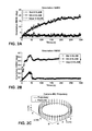
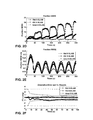
- FIGS. 2( a )- 2 ( f ) are plots associated with a first example simulation.
- the RMSE and NEES errors for orientation (a)-(b) and position (d)-(e) are plotted for all three filters, averaged per time step over 20 Monte Carlo trials.
- FIG. 2( c ) illustrate camera-IMU trajectory and 3D features.
- FIG. ( f ) illustrates error and 3 ⁇ bounds for the rotation about the gravity vector, plotted for the first 100 sec of a representative run.
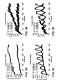
- FIGS. 3( a )- 3 ( d ) illustrate a set of plots associated with Simulation 2 including the average RMSE and NEES over 30 Monte-Carlo simulation trials for orientation (above) and position (below). Note that the OC-MSC-KF attained performance almost indistinguishable to the Ideal-MSC-KF.
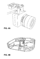
- FIG. 4( a ) is a perspective diagram showing an experimental test bed that comprises a light-weight InterSense NavChip IMU and a Point Grey Chameleon Camera.
- FIG. 4( b ) is a perspective diagram illustrating an AscTech Pelican on which the camera-IMU package was mounted during the indoor experiments.
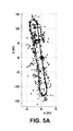
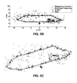
- FIGS. 5( a )- 5 ( c ) are a set of plots associated with Experiment 1 including the estimated 3D trajectory over the three traversals of the two floors of the building, along with the estimated positions of the persistent features.
- FIG. 5( a ) is a plot illustrating projection on the x and y axis.
- FIG. 5( b ) is a plot illustrating projection on the y and z axis.
- FIG. 5( c ) is a plot illustrating 3D view of the overall trajectory and the estimated features.
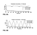
- FIGS. 6( a )- 6 ( b ) are a set of plots associated with Experiment 1 including comparison of the estimated 3 ⁇ error bounds for attitude and position between Std-V-SLAM and OC-V-SLAM.
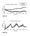
- FIGS. 7( a ) and ( 7 b ) are a set of plots associated with Experiment 2 including the position (a) and orientation (b) uncertainties (3 ⁇ bounds) for the yaw angle and the y-axis, which demonstrate that the Std-MSC-KF gains spurious information about its orientation.
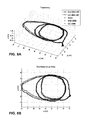
- FIGS. 8( a ) and 8 ( b ) are another set of plots for Experiment 2: The 3D trajectory (a) and corresponding overhead (x-y) view (b).
- FIGS. 9( a )- 9 ( c ) are perspective diagrams associated with Experiment 3.
- FIG. 9( a ) illustrates an outdoor experimental trajectory covering 1.5 km across the University of Minnesota campus.
- the red (blue) line denotes the OC-MSC-KF (Std-MSC-KF) estimated trajectory.
- the green circles denote a low-quality GPS-based estimate of the position across the trajectory.
- FIG. 9( b ) illustrates a zoom-in view of the beginning/end of the run.
- FIG. 9( c ) illustrates a zoomed-in view of the turn-around point.
- the Std-MSC-KF trajectory is shifted compared to the OC-MSC-KF, which remains on the path (light-brown region).
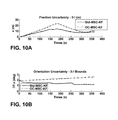
- FIGS. 10( a ) and 10 ( b ) are a set of plots for Experiment 3.
- FIG. 10( a ) illustrates position uncertainty along the x-axis (perpendicular to the direction of motion) for the Std-MSC-KF, and OC-MSC-KF respectively.
- FIG. 10( b ) illustrates orientation uncertainty about the vertical axis (z).
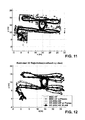
- FIG. 11 is a graph showing an overhead x-y view of the IMU-Kinect 3D trajectory and the point features estimated by the OC-MSC-KF SLAM.
- FIG. 12 is a graph showing IMU-Kinect trajectory estimated by the compared algorithms.
- the black triangle denotes the initial position of the IMU-Kinect pair.
- FIG. 13 shows a detailed example of various devices that may be configured to implement various embodiments in accordance with the current disclosure.
- VINS vision-aided inertial navigation systems
- a state estimator is “consistent” if the estimation errors are zero-mean and have covariance smaller than or equal to the one calculated by the filter.
- Estimator inconsistency can have a devastating effect, particularly in navigation applications, since both the current pose estimate and its uncertainty, must be accurate in order to address tasks that depend on the localization solution, such as path planning.
- several potential sources of inconsistency exist (e.g., motion-model mismatch in target tracking), and great care must be taken when designing an estimator to improve consistency.
- the estimation techniques may eliminate inconsistency due to spurious information gain which arises from approximations incurred when applying linear estimation tools to nonlinear problems (i.e., when using linearized estimators such as the extended Kalman Filter (EKF)).
- EKF extended Kalman Filter
- An estimator may, in accordance with the techniques described herein, apply a constrained estimation algorithm that computes the state estimates based on the IMU data and the image data while preventing projection of information from the image data and IMU data along at least one of the unobservable degrees of freedom.
- the techniques described herein may be applied in a variety of VINS domains (e.g., V-SLAM and the MSC-KF) when linearized estimators, such as the EKF, are used.
- an unobservable direction refers to a direction along which perturbations of the state cannot be detected from the input data provided by the sensors of the VINS. That is, an unobservable direction refers to a direction along which changes to the state of the VINS relative to one or more feature may be undetectable from the input data received from at least some of the sensors of the sensing platform.
- a rotation of the sensing system around a gravity vector may be undetectable from the input of a camera of the sensing system when feature rotation is coincident with the rotation of the sensing system.
- translation of the sensing system may be undetectable when observed features are identically translated.
- the observability properties of a linearized VINS model i.e., the one whose Jacobians are evaluated at the true states
- a linearized VINS model i.e., the one whose Jacobians are evaluated at the true states
- a linearized VINS model has four unobservable d.o.f., corresponding to three-d.o.f. global translations and one-d.o.f. global rotation about the gravity vector.
- the estimated states are used for evaluating the Jacobians, as is the case for the EKF
- the number of unobservable directions is reduced by one.
- the global rotation about the gravity vector becomes (erroneously) observable, allowing the estimator to gain spurious information and leading to inconsistency.
- an EKF is employed for fusing the camera and IMU measurements to estimate the state of the system including the pose, velocity, and IMU biases, as well as the 3D positions of visual landmarks observed by the camera.
- One example utilizes two types of visual features in a VINS framework. The first are opportunistic features (OFs) that can be accurately and efficiently tracked across short image sequences (e.g., using KLT), but are not visually distinctive enough to be efficiently recognized when revisiting an area. OFs can be efficiently used to estimate the motion of the camera over short time horizons (i.e., using the MSC-KF), but they are not included in the state vector.
- OFs opportunistic features
- the second are Persistent Features (PFs), which are typically much fewer in number, and can be reliably redetected when revisiting an area (e.g., SIFT keys).
- PFs Persistent Features
- 3D coordinates of the PFs e.g., identified points, lines, planes, or geometric shapes based on combinations thereof
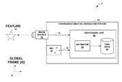
- FIG. 1 is a block diagram illustrating a vision-aided inertial navigation system (VINS) 10 comprises an image source 12 and an inertial measurement unit (IMU) 14 .
- Image source images an environment in which VINS 10 operates so as to produce image data 14 . That is, image source 12 provides image data 14 that captures a number of features visible in the environment.
- Image source 12 may be, for example, one or more cameras that capture 2D or 3D images, a laser scanner or other optical device that produces a stream of 1D image data, a depth sensor that produces image data indicative of ranges for features within the environment, a stereo vision system having multiple cameras to produce 3D information, and the like.
- IMU 16 produces IMU data 18 indicative of a dynamic motion of VINS 10 .
- IMU 14 may, for example, detect a current rate of acceleration using one or more accelerometers as VINS 10 is translated, and detect changes in rotational attributes like pitch, roll and yaw using one or more gyroscopes.
- IMU 14 produces IMU data 18 to specify the detected motion.
- Estimator 22 of processing unit 20 process image data 14 and IMU data 18 to compute state estimates for the degrees of freedom of VINS 10 and, from the state estimates, computes position, orientation, speed, locations of observable features, a localized map, an odometry or other higher order derivative information represented by VINS data 24 .
- ⁇ I q G ,G PI ⁇ are the quaternion of orientation and position vector describing the pose of the sensing IMU frame ⁇ I ⁇ with respect to the global frame ⁇ G ⁇ .
- the i-th feature's 3D coordinates are denoted as G ⁇ i , and I ⁇ i , with respect to ⁇ I ⁇ and ⁇ G ⁇ , respectively.
- estimator 22 comprises an EKF that estimates the 3D IMU pose and linear velocity together with the time-varying IMU biases and a map of visual features 15 .
- the filter state is the (16+3N) ⁇ 1 vector:
- x s (t) is the 16 ⁇ 1 state of VINS 10
- x ⁇ (t) is the 3N ⁇ 1 state of the feature map.
- the first component of the state of VINS 10 is G (t) which is the unit quaternion representing the orientation of the global frame ⁇ G ⁇ in the IMU frame, ⁇ I ⁇ , at time t.
- the frame ⁇ I ⁇ is attached to the IMU, while ⁇ G ⁇ is a local-vertical reference frame whose origin coincides with the initial IMU position.
- the state of VINS 10 also includes the position and velocity of ⁇ I ⁇ in ⁇ G ⁇ , denoted by the 3 ⁇ 1 vectors G p I (t) and G v I (t), respectively.
- the remaining components are the biases, b g (t) and b a (t), affecting the gyroscope and accelerometer measurements, which are modeled as random-walk processes driven by the zero-mean, white Gaussian noise n wg (t) and n wa (t), respectively.
- the VINS does not store OFs in the map. Instead, processing unit 20 of VINS 10 processes and marginalizes all OFs in real-time using the MSC-KF approach.
- An example continuous-time model which governs the state of VINS 10 .
- estimator 22 An example system model describing the time evolution of the state and applied by estimator 22 is represented as:
- G a is the IMU acceleration expressed in ⁇ G ⁇
- the matrix C q) is the rotation matrix corresponding to q.
- the PFs belong to the static scene, thus, their time derivatives are zero.
- the (15+3N) ⁇ 1 error-state vector is defined as
- x x ⁇ x is the error in the estimate ⁇ x of a quantity x.
- a multiplicative error model is employed for the quaternion. Specifically, the error between the quaternion q and its estimate ⁇ circumflex over ( ) ⁇ q is the 3 ⁇ 1 angle-error vector, ⁇ , implicitly defined by the error quaternion:
- ⁇ ⁇ ⁇ q _ q _ ⁇ ⁇ q - 1 ⁇ [ 1 2 ⁇ ⁇ T 1 ] T , ( 17 )
- ⁇ q describes the small rotation that causes the true and estimated attitude to coincide. This allows the attitude uncertainty to be represented by the 3 ⁇ 3 covariance matrix E[ ⁇ T ], which is a minimal representation.
- the IMU signals ⁇ m and a m are sampled by processing unit 20 at a constant rate 1/ ⁇ t, where ⁇ t t k+1 ⁇ t k .
- the state estimate is propagated by estimator 22 using 4th-order Runge-Kutta numerical integration of (10)-(15).
- the discrete-time state transition matrix, ⁇ k is computed, and the discrete-time system noise covariance matrix, Q k is computed as
- k ⁇ k P k
- j are used to denote the estimates of the error-state covariance and state, respectively, at time-step i computed using measurements up to time-step j.
- VINS 10 As VINS 10 moves, image source observes both opportunistic and persistent visual features. These measurements are utilized to concurrently estimate the motion of the sensing platform (VINS 10 ) and the map of PFs.
- three types of filter updates are distinguished: (i) PF updates of features already in the map, (ii) initialization of PFs not yet in the map, and (iii) OF updates.
- the feature measurement model is described how the model can be employed in each case.
- the image source measures z i , which is the perspective projection of the 3D point I f i , expressed in the current IMU frame ⁇ I ⁇ , onto the image plane, i.e.,
- the measurement noise, ⁇ i is modeled as zero mean, white Gaussian with covariance R i .
- H c is the Jacobian of the camera's perspective projection with respect to I f i
- H q , H p , and H f are the Jacobians of I f i with respect to I q G , G p I , and G f i .
- This measurement model is utilized in each of the three update methods.
- the measurement model (25)-(27) is directly applied to update the filter.
- S i H i P k+1
- K i P k+1
- the observability properties of the linearized VINS model are examined. Specifically, the four unobservable directions of the ideal linearized VINS are analytically determined (i.e., the system whose Jacobians are evaluated at the true states). Subsequently, the linearized VINS used by the EKF, whose Jacobians are evaluated using the current state estimates, are shown to have only three unobservable directions (i.e., the ones corresponding to global translation), while the one corresponding to global rotation about the gravity vector becomes (erroneously) observable. The findings of this analysis are then employed to improve the consistency of the EKF-based VINS.
- An observability matrix is defined as a function of the linearized measurement model, H, and the discrete-time state transition matrix, ⁇ , which are in turn functions of the linearization point, x*, i.e.,
- M ⁇ ( x * ) [ H 1 H 2 ⁇ ⁇ 2 , 1 ⁇ H k ⁇ ⁇ k , 1 ] ( 37 )
- the solution has the following structure
- ⁇ k , 1 [ ⁇ 11 ⁇ 12 0 3 0 3 0 3 0 3 0 3 I 3 0 3 0 3 0 3 0 3 ⁇ 31 ⁇ 32 I 3 ⁇ 34 0 3 0 3 0 3 0 3 0 3 I 3 0 3 0 3 ⁇ 51 ⁇ 52 ⁇ ⁇ ⁇ t ⁇ ( k - 1 ) ⁇ I 3 ⁇ 54 I 3 0 3 0 3 0 3 0 3 0 3 I 3 ] ( 42 ) where among the different block elements ⁇ ij , the ones necessary in the analysis are listed below:
- the k-th block row of M is obtained, for k>1:
- N 1 is indeed the right nullspace of M(x) can be verified by multiplying each block row of M [see (46)] with N t,1 and N r,1 in (52).
- the 18 ⁇ 3 block column N t,1 corresponds to global translations, i.e., translating both the sensing platform and the landmark by the same amount.
- the 18 ⁇ 1 column N r,1 corresponds to global rotations of the sensing platform and the landmark about the gravity vector.
- any VINS estimator should employ a linearized system with an unobservable subspace that matches the true unobservable directions (52), both in number and structure.
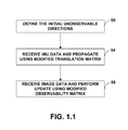
- FIG. 1.1 is a flowchart illustrating an example operation of estimator 22 applying the techniques described here. Although illustrated for purposes of example as sequential, the steps of the flowchart may be performed concurrently.
- estimator 22 defines the initial unobservable directions, e.g., computes an initial nullspace from (eq. 55) for the particular system (STEP 50 ).
- the unobservable degrees of freedom comprise translations in horizontal and vertical directions and a rotation about a gravity vector. In another example, such as with respect to use of line features, other degrees of freedom may be unobservable.
- Estimator 22 receives IMU data 18 and, based on the IMU data 18 , performs propagation by computing updated state estimates and propagating the covariance. At this time, estimator 22 utilizes a modified a state transition matrix to prevent correction of the state estimates along at least one of the unobservable degrees of freedom (STEP 54 ). In addition, estimator 22 receives image data 14 and updates the state estimates and covariance based on the image data. At this time, estimator 22 uses a modified observability matrix to similarly prevent correction of the state estimates along at least one of the unobservable degrees of freedom (STEP 58 ).
- estimator 22 enforces the unobservable directions of the system, thereby preventing one or more unobservable directions from erroneously being treated as observable after estimation, thereby preventing spurious information gain and reducing inconsistency.
- processing unit 20 may more accurately compute state information for VINS 10 , such as a pose of the vision-aided inertial navigation system, a velocity of the vision-aided inertial navigation system, a displacement of the vision-aided inertial navigation system based at least in part on the state estimates for the subset of the unobservable degrees of freedom without utilizing state estimates the at least one of the unobservable degrees of freedom.
- Initialization Initialization: Compute initial nullspace from (55) while running do Propagation: Integrate state equations Compute nullspace at current time-step from (56) Compute ⁇ k from (22) Modify ⁇ k using (60) - (62) Propagate covariance Update: for all observed features do Compute measurement Jacobian from (27) Modify H using (69)-(74) Apply filter updated end for New landmark initialization: for all new PFs observed do Initialize G ⁇ circumflex over (f) ⁇ i , Create nullspace block, N f i , for G ⁇ circumflex over (f) ⁇ i Augment N k with the new sub-block N f i end for end while
- the nullspace, ⁇ circumflex over (N) ⁇ k is maintained at each time step, and used to enforce the unobservable directions. This has the benefit of allowing us to linearize with the most accurate state estimates, hence reducing the linearization error, while still explicitly adhering to the system observability properties.
- the initial nullspace is analytically defined:
- N ⁇ 1 [ 0 3 C ⁇ ( I q _ ⁇ G , 0 ⁇ 0 ) G g 0 3 0 3 - ⁇ G V ⁇ I , 0 ⁇ 0 ⁇ ⁇ G g 0 3 0 3 I 3 - ⁇ G p I , 0 ⁇ 0 ⁇ ⁇ G g I 3 - ⁇ G f ⁇ I , 0 ⁇ 0 ⁇ ⁇ G g ] ( 55 )
- the nullspace is augmented to include sub-blocks corresponding to each new PF in the filter state, i.e.,
- N ⁇ k [ 0 3 C ⁇ ( q _ ⁇ G , k ⁇ k - 1 1 ) G ⁇ g 0 3 0 3 - ⁇ G ⁇ v ⁇ I , k ⁇ k - 1 ⁇ ⁇ G ⁇ g 0 3 0 3 I 3 - ⁇ G ⁇ p ⁇ I , k ⁇ k - 1 ⁇ ⁇ G ⁇ g I 3 - ⁇ G ⁇ f ⁇ I , k ⁇ k - l ⁇ ⁇ G ⁇ g ⁇ ⁇ I 3 - ⁇ G ⁇ f ⁇ N , k ⁇ k - l ′ ⁇ ⁇ G ⁇ g ] .
- the filter update is performed. By following this process, it can be ensured that the EKF estimator 22 does not gain information along the unobservable directions of the system.
- An overview of one example of the OC-VINS modified EKF estimator is presented in Algorithm 1.
- ⁇ T ] T , where x s,i , i 1 . . . m, are the m camera poses which the new landmark, f, was observed from. Specifically, the following is minimized:
- V-SLAM Visual Simultaneous Localization and Mapping
- MSC-KF Multi-state Constraint Kalman Filter
- V-SLAM Visual Simultaneous Localization and Mapping
- V-SLAM the Visual Simultaneous Localization and Mapping
- the current IMU pose, as well as the 3D positions of all visual landmarks are jointly estimated.
- the performance of OC-SLAM described herein is compared to the standard V-SLAM (Std-V-SLAM), as well as the ideal V-SLAM that linearizes about the true state.
- RMSE Root Mean Squared Error
- NEES Normalized Estimation Error Squared
- FIG. 2 also displays the RMSE and NEES plots, in which it is observed that the OC-V-SLAM attains orientation accuracy and consistency levels similar to the Ideal-V-SLAM, while significantly outperforming the Std-V-SLAM. Similarly, the OC-V-SLAM obtains better positioning accuracy compared to the Std-V-SLAM.
- OC-MSC-KF MSC-KF
- all the measurements to a given OF are incorporated during a single update step of the filter, after which each OF is marginalized.
- the proposed OC-VINS framework were also validated experimentally and compared with standard VINS approaches. Specifically, the performance of OC-V-SLAM and OC-MSC-KF were evaluated on both indoor and outdoor datasets.
- a light-weight sensing platform comprised of an InterSense NavChip IMU and a PointGrey Chameleon camera (see FIG. 4( a )) was utilized. IMU signals are sampled at a frequency of 100 Hz while camera images are acquired at 7.5 Hz.
- the dimensions of the sensing package in this example are approximately 6 cm tall, by 5 cm wide, by 8 cm deep.
- the sensing platform was mounted on an Ascending Technologies Pelican quadrotor equipped with a VersaLogic Core 2 Duo single board computer.
- the sensing platform was head-mounted on a bicycle helmet, and interfaced to a handheld Sony Vaio. An overview of the system implementation is described, along with a discussion of the experimental setup and results.
- the image processing is separated into two components: one for extracting and tracking short-term opportunistic features (OFs), and one for extracting persistent features (PFs) to use in V-SLAM.
- OFs short-term opportunistic features
- PFs persistent features
- OFs are extracted from images using the Shi-Tomasi corner detector. After acquiring image k, it is inserted into a sliding window buffer of m images, ⁇ k ⁇ m+1, k ⁇ m+2, . . . , k ⁇ . We then extract features from the first image in the window and track them pairwise through the window using the KLT tracking algorithm. To remove outliers from the resulting tracks, we use a two-point algorithm to find the essential matrix between successive frames. Specifically, given the filter's estimated rotation (from the gyroscopes' measurements) between image i and j, , we estimate the essential matrix from only two feature correspondences. This approach is more robust than the five-point algorithm because it provides two solutions for the essential matrix rather than up to ten. Moreover, it requires only two data points, and thus it reaches a consensus with fewer hypotheses when used in a RANSAC framework.
- the PFs are extracted using SIFT descriptors.
- VT vocabulary tree
- the VT is used to select which image(s) taken at times 1, 2, . . . , k ⁇ 1 correspond to the same physical scene.
- the SIFT descriptors from each of them are compared to those from image k to create tentative feature correspondences.
- the epipolar constraint is then enforced using RANSAC and Nister's five-point algorithm to eliminate outliers. It is important to note that the images used to construct the VT (offline) are not taken along our experimental trajectory, but rather are randomly selected from a set of representative images.
- the final position error was approximately 34 cm, which is less than 0.2% of the total distance traveled (see FIG. 5 ).
- the estimated covariances from the Std-V-SLAM are smaller than those from the OC-V-SLAM (see FIGS. 6( a )- 6 ( b )).
- uncertainty estimates from the Std-V-SLAM decreased in directions that are unobservable (i.e., rotations about the gravity vector); this violates the observability properties of the system and demonstrates that spurious information is injected to the filter.
- FIG. 6( a ) highlights the difference in estimated yaw uncertainty between the OC-V-SLAM and the Std-V-SLAM.
- the Std-V-SLAM covariance rapidly decreases, violating the observability properties of the system.
- large differences can be seen in the covariance estimates for the x-axis position estimates (see FIG. 6( b )).
- the Std-V-SLAM estimates a much smaller uncertainty than the OC-V-SLAM, supporting the claim that the Std-V-SLAM tends to be inconsistent.
- the proposed OC-MSC-KF was validated on real-world data.
- the first test comprised a trajectory 50 m in length that covered three loops in an indoor area, after which the testbed was returned to its initial position.
- the Std-MSC-KF had a position error of 18.73 cm, while the final error for the OC-MSC-KF was 16.39 cm (approx. 0.38% and 0.33% of the distance traveled, respectively).
- the rotation between the first and last images computed independently using Batch Least-Squares (BLS) and feature point matches was used as ground truth.
- the Std-MSC-KF had final orientation error [0.15 ⁇ 0.23 ⁇ 5.13] degrees for roll, pitch, and yaw (rpy), while the rpy errors for the OC-MSC-KF were [0.19 ⁇ 0.20 ⁇ 1.32] degrees respectively.
- the OC-MSC-KF is more conservative since it strictly adheres to the unobservable directions of the system. This is evident in both the position and orientation uncertainties.
- the y-axis position and yaw angle uncertainties is plotted in FIG. 7 , as representative results. Most notably, the yaw uncertainty of the OC-MSC-KF remains approximately 1.13 deg (3 ⁇ ), while for the Std-MSC-KF it reduces to 0.87 deg (3 ⁇ ). This indicates that the Std-MSC-KF gains spurious orientation information, which leads to inconsistency.
- FIG. 8 shows the 3D trajectory along with an overhead (x-y) view. It is evident that the Std-MSC-KF yaw error impacts the position accuracy, as the Std-MSC-KF trajectory exhibits a rotation with respect to the OC-MSC-KF.
- FIG. 9( a ) depicts the OC-MSC-KF (red) and the Std-MSC-KF (blue) trajectory estimates, along with position markers from a low-grade onboard GPS receiver (green).
- the estimates are overlaid on an overhead image.
- FIG. 9( b ) depicts a zoomed-in plot of the starting location (center) for both filters, along with the final position estimates.
- the sensing platform was returned to its starting location at the end of the trajectory.
- the OC-MSC-KF obtains a final position error of 4.38 m (approx. 0.3% of the distance traveled), while the Std-MSC-KF obtains a final position error of 10.97 m. This represents an improvement in performance of approximately 60%.
- FIG. 9( c ) shows a zoomed-in plot of the turn-around point.
- the OC-MSC-KF estimates remain on the light-brown portion of the ground (which is the sidewalk), which coincides with the true trajectory.
- the Std-MSC-KF estimates drift over the dark triangles in the image, which are wading pools filled with water. This shifting of the trajectory represents a slight rotation around the vertical axis, indicating a violation of the rotation nullspace direction N r .
- FIG. 10 depicts the uncertainty in the position estimates along the x-axis (perpendicular to the direction of motion), along with the uncertainty in yaw (corresponding to rotations about the gravity vector).
- FIG. 10( a ) illustrates position uncertainty along the x-axis (perpendicular to the direction of motion) for the Std-MSC-KF, and OC-MSC-KF respectively.
- the OC-MSC-KF maintains more conservative estimates for position, indicating that the Std-MSC-KF may be inconsistent.
- FIG. 10( b ) illustrates orientation uncertainty about the vertical axis (z). Since rotations about gravity are unobservable, the Std-MSC-KF should not gain any information in this direction.
- the Std-MSC-KF uncertainty reduces, indicating inconsistency.
- the uncertainty does not decrease, indicating that the OC-MSC-KF respects the unobservable system directions. It is clear that the Std-MSC-KF reduces its uncertainty in its heading direction, indicating that the filter gains spurious information, while the OC-MSC-KF does not gain information for the rotation around the gravity vector.
- RGBD cameras provide both color images and the corresponding 3D point cloud, which simplifies the tasks of triangulating point-feature positions and extracting higher level features, such as planes, from the scene.
- one degree of rotational freedom (yaw) of the IMU-RGBD camera is unobservable.
- the uncertainty and error in the yaw estimates will keep increasing, hence, adversely affecting the positioning accuracy.
- a linear-complexity inertial navigation algorithm uses both point and plane features.
- system observability properties including its observable modes and unobservable directions, are described.
- point feature measurements are processed using a tightly-coupled visual-inertial odometry, multi-state constraint Kalman filter (MSC-KF), with complexity linear in the number of observed point features.
- MSC-KF multi-state constraint Kalman filter
- the directions of the plane features are used as measurements in the extended Kalman filter update without including the plane feature poses in the state vector, hence ensuring linear complexity in the number of the observed plane features.
- the observability of the IMU-RGBD camera navigation system when using both point and plane feature measurements is described, and it is proved that with a single plane feature of known direction, the IMU gyroscope bias is observable. If additionally a single point feature is detected, and the plane's normal vector is not aligned with gravity, all degrees of freedom of the IMU-RGBD camera navigation system, except the global position, become observable. Based on the observability analysis, the accuracy and consistency of the IMU-RGBD camera navigation system is improved by employing the observability-constrained extended Kalman filter that enforces the observability requirement.
- a linear-complexity algorithm for fusing inertial measurements with both point and plane features is presented and experimentally validated.
- the rest of this section is structured as follows. First, the inertial navigation system model using both point and plane feature measurements is presented. A methodology for studying the observability properties of unobservable nonlinear systems is described. The method is applied to the specific IMU-RGBD camera navigation system, and its unobservable directions are described. The OC-EKF algorithm developed for improving the accuracy and consistency of the inertial navigation system based on its observability properties is presented. Experimental results for the performance of the proposed algorithm are described and assessed.
- Iq G is the unit quaternion representing the orientation of the global frame ⁇ G ⁇ in the IMU's frame of reference ⁇ I ⁇
- Gv I and Gp I represent the velocity and position of ⁇ I ⁇ in ⁇ G ⁇
- Gp ⁇ denotes the position of the point feature in ⁇ G ⁇
- b a and b g represent the gyroscope and accelerometer biases.
- the system model describing the time evolution of the states can be represented as:
- g ⁇ ( t ) w ⁇ ⁇ ⁇ g ( A ⁇ .1 )
- w wa and w wg are zero-mean white Gaussian noise processes driving the gyroscope and accelerometer biases b g and b a
- G g is the gravitational acceleration in ⁇ G ⁇
- C(Iq G (t)) denotes the rotation matrix corresponding to Iq G (t)
- ⁇ tilde over (x) ⁇ [ I ⁇ G T G ⁇ tilde over (V) ⁇ I T G ⁇ tilde over (p) ⁇ I T G ⁇ tilde over (p) ⁇ ⁇ T ⁇ tilde over (b) ⁇ a T ⁇ tilde over (b) ⁇ g T ] T (A.4)
- the propagated covariance can be determined as: P K+1
- k ⁇ k P k
- the IMU frame ⁇ I ⁇ and the RGBD-camera frame ⁇ C ⁇ are assumed to coincide.
- G n denote the normal vector to a plane, whose direction is assumed known in the global frame of reference, and thus we need not include it in the state vector.
- Planes are fitted in the 3D point cloud provided by the RGBD camera, and its normal vector, z plane , is used as the plane feature measurement:
- ⁇ ⁇ ak is the measurement noise representing a rotation by an angle ⁇ around the unit vector k.
- y is the system output
- the observability matrix of system (A.17) is defined as a matrix with block rows the span of the Lie derivatives of (A.17), i.e.,
- the unobservable directions can be determined with significantly less effort.
- Theorem 1 is leveraged to study the observability of the IMU-RGBD camera navigation system when using plane and point feature observations. To do this, the system's basis functions are found, which are also the observable modes, using only a single plane feature. Then, the basis function set for the IMU-RGBD camera navigation system is completed using both plane and point features. Finally, the unobservable directions of the IMU-RGBD camera navigation system when using only plane observations is found, and when using both plane and point feature measurements.
- the IMU-RGBD camera navigation system using only plane features can be written as:
- ⁇ ⁇ ⁇ x ⁇ f 1 is a function of ⁇ for any i), is satisfied by all the basis functions.
- ⁇ 1 is a 3 ⁇ 1 vector representing in a compact form 3 basis functions.
- condition (A3) of Theorem 1 is used to define additional basis functions as nonlinear combinations of the system's Lie derivatives.
- b g is a function of the Lie derivatives, and we define it as a new basis function: ⁇ 2 b g (A.31) Then, if the span of ⁇ 2 is computed and projected onto the process functions, the result is
- the unobservable directions of the IMU-RGBD camera navigation system is first determined when observing only a single plane feature by computing the nullspace of the basis functions' span,
- Theorem 2 The IMU-RGBD camera navigation system observing a single plane feature is unobservable, and its unobservable directions are spanned by the IMU-RGBD camera orientation around the plane's normal vector and the accelerometer bias in the IMU frame ⁇ I ⁇ , as well as the IMU-RGBD camera position, velocity, and the point feature position in the global frame ⁇ G ⁇ .
- Theorem 3 The IMU-RGBD camera navigation system using a single point feature and a single plane feature (of known direction which is not parallel to gravity) is unobservable, and its unobservable subspace is spanned by 3 directions corresponding to the IMU-RGBD camera position in the global frame ⁇ G ⁇ .
- N [N 1 T N 2 T N 3 T N 4 T N 5 T N 6 T ] T be the right nullspace of matrix B 2 .
- N 3 N 4 ⁇ I 3
- N 2 0 3 .
- Gaussian elimination it is easy to show that the rank of matrix B 2 is 15.
- the dimension of its right nullspace is exactly three, and the system's unobservable directions are spanned by: N [ 0 3 0 3 I 3 I 3 0 3 0 3 ] T (A.40) which corresponds to the global position of the IMU-RGBD camera and the point feature. Intuitively, this means that translating the IMU-RGBD camera and the point feature positions concurrently has no impact on the system's measurements.
- the unobservable directions of the IMU-RGBD camera navigation system using only a single point feature are spanned by:
- N N plane ⁇ N point , which makes sense because any unobservable quantity of the IMU-RGBD camera navigation system using both point and plane feature observations, must be unobservable when the system uses either plane or point feature measurements.
- This section presents an example IMU-RGBD camera navigation algorithm employing the observability constrained (OC)-EKF, which seeks to maintain the original system's observability properties in the linearized implementation (EKF).
- OC-EKF observability constrained
- EKF linearized implementation
- a system's observability Gramian, M is defined as:
- M [ H 1 H 2 ⁇ ⁇ 2 , 1 ⁇ H k ⁇ ⁇ k , 1 ] ( A ⁇ .42 ) where ⁇ k,1 k ⁇ 1 . . . ⁇ 1 is the state transition matrix from time step 1 to k, and H k is the measurement Jacobian at time step k.
- (A.43) does not hold when a nonlinear system is linearized using the current state estimate.
- the EKF gains spurious information along unobservable directions, which results in smaller uncertainty (that causes the filter to be inconsistent) and larger estimation errors.
- the OC-EKF modifies the state transition and measurement Jacobian matrices in such a way so that the resulting linearized system adheres to the observability properties of the original nonlinear system.
- N k and N k+1 are the unobservable directions evaluated at time-steps k and k+1.
- N point k+1 ⁇ k N point k (A.46)
- N point k and N point k+1 defined in (41)
- ⁇ k has the following structure:
- ⁇ 11 k C k+1 C K T is modified. Therefore, multiplying N plane g and N plane p to the right hand side of M plane , we have:
- An experimental setup was constructed comprising an InterSenseTM NavChip IMU and a KinectTM sensor, which contained an RGB camera and an infrared (IR) depth-finding camera.
- the intrinsic parameters of the Kinect RGB camera and IR camera, as well as the transformation between them, were determined offline using the algorithm described in D. Herrera, J. Kannala, and J. Heikkila, “Joint depth and color camera calibration with distortion correction,” IEEE Trans. on Pattern Analysis and Machine Intelligence, vol. 34, no. 10, pp. 2058-2064, October 2012, incorporated herein by reference.
- the IMU signals were sampled at 100 Hz, and the Kinect provided RGBD images at a frequency of 6.3 Hz.
- the plane features are extracted from the RGBD images using the method proposed in C. Amsterdam, M. Paluri, and F. Dellaert, “Planar segmentation of RGBD images using fast linear fitting and markov chain monte carlo,” in Proc. of the IEEE International Conference on Computer and Robot Vision, Toronto, Canada, May 27-30 2012, pp. 32-39, incorporated herein by reference.
- FIG. 11 is a graph showing the overhead x-y view of the IMU-Kinect 3D trajectory and the point features estimated by the OC-MSC-KF SLAM.
- FIG. 12 is a graph showing IMU-Kinect trajectory estimated by the compared algorithms. The black triangle denotes the initial position of the IMU-Kinect pair. The 3D trajectory of the IMU-Kinect pair and the point features, estimated by OC-MSC-KF SLAM, are plotted in FIG. 11 . The 3D trajectories estimated by the algorithms considered are shown in FIG. 12 , and their final errors are reported in Table I.
- OC-MSC-KF SLAM has the lowest final error, and our proposed algorithm, OC-MSC-KF w/ Planes, outperforms the other four algorithms. Additionally, the algorithms using both point and plane feature measurements (MSC-KF w/ Planes and OC-MSC-KF w/ Planes), have much smaller final error and perform closer to the OC-MSC-KF SLAM. This is because the plane features provide periodic corrections to the IMU-RGBD camera pair's orientation, thus also improving its position estimation accuracy. Finally, we note that enforcing the observability constraints (OC-MSC-KF and OC-MSC-KF w/ Planes) results in better accuracy since the filters do not process spurious information.
- the previous section presented presents an algorithm for fusing inertial measurements, as well as point and plane feature observations captured from one or more image sources, such as an IMU-RGBD camera navigation system. Specifically, it was shown that by observing only a single plane feature of know direction, only the plane's direction in the IMU frame and the gyroscope bias are observable. Then, it was shown that by observing a single point feature and a single plane feature, of known direction other than the gravity, all the estimated quantities in the IMU-RGBD camera navigation system become observable, except the IMU-RGBD camera position in the global frame. Based on the observability analysis, an OC-EKF was described that significantly improves the estimation accuracy and consistency by removing spurious information along unobservable directions from the estimator.
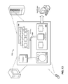
- FIG. 13 shows a detailed example of various devices that may be configured to implement some embodiments in accordance with the current disclosure.
- device 500 may be a mobile sensing platform, a mobile phone, a workstation, a computing center, a cluster of servers or other example embodiments of a computing environment, centrally located or distributed, capable of executing the techniques described herein. Any or all of the devices may, for example, implement portions of the techniques described herein for vision-aided inertial navigation system.
- a computer 500 includes a processor 510 that is operable to execute program instructions or software, causing the computer to perform various methods or tasks, such as performing the enhanced estimation techniques described herein.
- Processor 510 is coupled via bus 520 to a memory 530 , which is used to store information such as program instructions and other data while the computer is in operation.
- a storage device 540 such as a hard disk drive, nonvolatile memory, or other non-transient storage device stores information such as program instructions, data files of the multidimensional data and the reduced data set, and other information.
- the computer also includes various input-output elements 550 , including parallel or serial ports, USB, Firewire or IEEE 1394, Ethernet, and other such ports to connect the computer to external device such a printer, video camera, surveillance equipment or the like.
- Other input-output elements include wireless communication interfaces such as Bluetooth, Wi-Fi, and cellular data networks.
- the computer itself may be a traditional personal computer, a rack-mount or business computer or server, or any other type of computerized system.
- the computer in a further example may include fewer than all elements listed above, such as a thin client or mobile device having only some of the shown elements.
- the computer is distributed among multiple computer systems, such as a distributed server that has many computers working together to provide various functions.
- the techniques described herein may be implemented in hardware, software, firmware, or any combination thereof.
- Various features described as modules, units or components may be implemented together in an integrated logic device or separately as discrete but interoperable logic devices or other hardware devices.
- various features of electronic circuitry may be implemented as one or more integrated circuit devices, such as an integrated circuit chip or chipset.
- this disclosure may be directed to an apparatus such a processor or an integrated circuit device, such as an integrated circuit chip or chipset.
- the techniques may be realized at least in part by a computer readable data storage medium comprising instructions that, when executed, cause one or more processors to perform one or more of the methods described above.
- the computer-readable data storage medium or device may store such instructions for execution by a processor. Any combination of one or more computer-readable medium(s) may be utilized.
- a computer-readable storage medium may form part of a computer program product, which may include packaging materials.
- a computer-readable storage medium may comprise a computer data storage medium such as random access memory (RAM), read-only memory (ROM), non-volatile random access memory (NVRAM), electrically erasable programmable read-only memory (EEPROM), flash memory, magnetic or optical data storage media, and the like.
- RAM random access memory
- ROM read-only memory
- NVRAM non-volatile random access memory
- EEPROM electrically erasable programmable read-only memory
- flash memory magnetic or optical data storage media, and the like.
- a computer-readable storage medium may be any tangible medium that can contain or store a program for use by or in connection with an instruction execution system, apparatus, or device. Additional examples of computer readable medium include computer-readable storage devices, computer-readable memory, and tangible computer-readable medium.
- an article of manufacture may comprise one or more computer-readable storage media.
- the computer-readable storage media may comprise non-transitory media.
- the term “non-transitory” may indicate that the storage medium is not embodied in a carrier wave or a propagated signal.
- a non-transitory storage medium may store data that can, over time, change (e.g., in RAM or cache).
- the code or instructions may be software and/or firmware executed by processing circuitry including one or more processors, such as one or more digital signal processors (DSPs), general purpose microprocessors, application-specific integrated circuits (ASICs), field-programmable gate arrays (FPGAs), or other equivalent integrated or discrete logic circuitry.
- DSPs digital signal processors
- ASICs application-specific integrated circuits
- FPGAs field-programmable gate arrays
- processors may refer to any of the foregoing structure or any other processing circuitry suitable for implementation of the techniques described herein.
- functionality described in this disclosure may be provided within software modules or hardware modules.
- This disclosure analyzed the inconsistency of VINS from the standpoint of observability. For example, it was showed that standard EKF-based filtering approaches lead to spurious information gain since they do not adhere to the unobservable directions of the true system. Furthermore, an observability-constrained VINS approach was applied to mitigate estimator inconsistency by enforcing the nullspace explicitly. An extensive simulation and experimental results were presented to support and validate the described estimator, by applying it to both V-SLAM and the MSC-KF.
Landscapes
- Engineering & Computer Science (AREA)
- Radar, Positioning & Navigation (AREA)
- Remote Sensing (AREA)
- Physics & Mathematics (AREA)
- General Physics & Mathematics (AREA)
- Automation & Control Theory (AREA)
- Theoretical Computer Science (AREA)
- Computer Vision & Pattern Recognition (AREA)
- Multimedia (AREA)
- Robotics (AREA)
- Mechanical Engineering (AREA)
- General Engineering & Computer Science (AREA)
- Signal Processing (AREA)
- Human Computer Interaction (AREA)
- Navigation (AREA)
Priority Applications (1)
| Application Number | Priority Date | Filing Date | Title |
|---|---|---|---|
| US14/186,597 US9243916B2 (en) | 2013-02-21 | 2014-02-21 | Observability-constrained vision-aided inertial navigation |
Applications Claiming Priority (3)
| Application Number | Priority Date | Filing Date | Title |
|---|---|---|---|
| US201361767691P | 2013-02-21 | 2013-02-21 | |
| US201361767701P | 2013-02-21 | 2013-02-21 | |
| US14/186,597 US9243916B2 (en) | 2013-02-21 | 2014-02-21 | Observability-constrained vision-aided inertial navigation |
Publications (2)
| Publication Number | Publication Date |
|---|---|
| US20140316698A1 US20140316698A1 (en) | 2014-10-23 |
| US9243916B2 true US9243916B2 (en) | 2016-01-26 |
Family
ID=51391862
Family Applications (2)
| Application Number | Title | Priority Date | Filing Date |
|---|---|---|---|
| US14/186,597 Active US9243916B2 (en) | 2013-02-21 | 2014-02-21 | Observability-constrained vision-aided inertial navigation |
| US14/768,733 Active 2035-08-05 US10254118B2 (en) | 2013-02-21 | 2014-02-21 | Extrinsic parameter calibration of a vision-aided inertial navigation system |
Family Applications After (1)
| Application Number | Title | Priority Date | Filing Date |
|---|---|---|---|
| US14/768,733 Active 2035-08-05 US10254118B2 (en) | 2013-02-21 | 2014-02-21 | Extrinsic parameter calibration of a vision-aided inertial navigation system |
Country Status (2)
| Country | Link |
|---|---|
| US (2) | US9243916B2 (e) |
| WO (1) | WO2014130854A1 (e) |
Cited By (40)
| Publication number | Priority date | Publication date | Assignee | Title |
|---|---|---|---|---|
| US20170193299A1 (en) * | 2016-01-05 | 2017-07-06 | Electronics And Telecommunications Research Institute | Augmented reality device based on recognition of spatial structure and method thereof |
| US9709404B2 (en) | 2015-04-17 | 2017-07-18 | Regents Of The University Of Minnesota | Iterative Kalman Smoother for robust 3D localization for vision-aided inertial navigation |
| US9766074B2 (en) | 2008-03-28 | 2017-09-19 | Regents Of The University Of Minnesota | Vision-aided inertial navigation |
| CN108133028A (zh) * | 2017-12-28 | 2018-06-08 | 北京天睿空间科技股份有限公司 | 基于视频分析与定位信息结合的航空器挂牌方法 |
| US9996941B2 (en) | 2013-05-08 | 2018-06-12 | Regents Of The University Of Minnesota | Constrained key frame localization and mapping for vision-aided inertial navigation |
| US10012504B2 (en) | 2014-06-19 | 2018-07-03 | Regents Of The University Of Minnesota | Efficient vision-aided inertial navigation using a rolling-shutter camera with inaccurate timestamps |
| US10203209B2 (en) | 2016-05-25 | 2019-02-12 | Regents Of The University Of Minnesota | Resource-aware large-scale cooperative 3D mapping using multiple mobile devices |
| US10217234B2 (en) | 2017-01-26 | 2019-02-26 | Samsung Electronics Co., Ltd. | Modeling method and apparatus using three-dimensional (3D) point cloud |
| US10254118B2 (en) | 2013-02-21 | 2019-04-09 | Regents Of The University Of Minnesota | Extrinsic parameter calibration of a vision-aided inertial navigation system |
| US10295365B2 (en) * | 2016-07-29 | 2019-05-21 | Carnegie Mellon University | State estimation for aerial vehicles using multi-sensor fusion |
| US10317901B2 (en) | 2016-09-08 | 2019-06-11 | Mentor Graphics Development (Deutschland) Gmbh | Low-level sensor fusion |
| US10371529B2 (en) | 2014-07-11 | 2019-08-06 | Regents Of The University Of Minnesota | Computational budget estimation for vision-aided inertial navigation systems |
| US10435176B2 (en) * | 2016-05-25 | 2019-10-08 | Skydio, Inc. | Perimeter structure for unmanned aerial vehicle |
| US10436595B2 (en) * | 2017-02-02 | 2019-10-08 | Baidu Usa Llc | Method and system for updating localization maps of autonomous driving vehicles |
| US10466695B2 (en) | 2014-06-19 | 2019-11-05 | Skydio, Inc. | User interaction paradigms for a flying digital assistant |
| US10520904B2 (en) | 2016-09-08 | 2019-12-31 | Mentor Graphics Corporation | Event classification and object tracking |
| US10520943B2 (en) | 2016-08-12 | 2019-12-31 | Skydio, Inc. | Unmanned aerial image capture platform |
| US10553044B2 (en) | 2018-01-31 | 2020-02-04 | Mentor Graphics Development (Deutschland) Gmbh | Self-diagnosis of faults with a secondary system in an autonomous driving system |
| US10636190B2 (en) | 2018-05-31 | 2020-04-28 | Robert Bosch Gmbh | Methods and systems for exploiting per-pixel motion conflicts to extract primary and secondary motions in augmented reality systems |
| US10678240B2 (en) | 2016-09-08 | 2020-06-09 | Mentor Graphics Corporation | Sensor modification based on an annotated environmental model |
| US10732647B2 (en) * | 2013-11-27 | 2020-08-04 | The Trustees Of The University Of Pennsylvania | Multi-sensor fusion for robust autonomous flight in indoor and outdoor environments with a rotorcraft micro-aerial vehicle (MAV) |
| US10757485B2 (en) | 2017-08-25 | 2020-08-25 | Honda Motor Co., Ltd. | System and method for synchronized vehicle sensor data acquisition processing using vehicular communication |
| US10816967B2 (en) | 2014-06-19 | 2020-10-27 | Skydio, Inc. | Magic wand interface and other user interaction paradigms for a flying digital assistant |
| US10852412B2 (en) * | 2018-10-18 | 2020-12-01 | Bae Systems Information And Electronic Systems Integration Inc. | Bullet state estimator using observer based dynamic system |
| US10884409B2 (en) | 2017-05-01 | 2021-01-05 | Mentor Graphics (Deutschland) Gmbh | Training of machine learning sensor data classification system |
| US10884430B2 (en) | 2015-09-11 | 2021-01-05 | The Trustees Of The University Of Pennsylvania | Systems and methods for generating safe trajectories for multi-vehicle teams |
| US10907971B2 (en) | 2017-12-08 | 2021-02-02 | Regents Of The University Of Minnesota | Square root inverse Schmidt-Kalman filters for vision-aided inertial navigation and mapping |
| US11067996B2 (en) | 2016-09-08 | 2021-07-20 | Siemens Industry Software Inc. | Event-driven region of interest management |
| US11145146B2 (en) | 2018-01-31 | 2021-10-12 | Mentor Graphics (Deutschland) Gmbh | Self-diagnosis of faults in an autonomous driving system |
| US11163317B2 (en) | 2018-07-31 | 2021-11-02 | Honda Motor Co., Ltd. | System and method for shared autonomy through cooperative sensing |
| US11181929B2 (en) | 2018-07-31 | 2021-11-23 | Honda Motor Co., Ltd. | System and method for shared autonomy through cooperative sensing |
| US11295458B2 (en) | 2016-12-01 | 2022-04-05 | Skydio, Inc. | Object tracking by an unmanned aerial vehicle using visual sensors |
| US11410178B2 (en) | 2020-04-01 | 2022-08-09 | Mastercard International Incorporated | Systems and methods for message tracking using real-time normalized scoring |
| US11466990B2 (en) | 2016-07-22 | 2022-10-11 | Regents Of The University Of Minnesota | Square-root multi-state constraint Kalman filter for vision-aided inertial navigation system |
| US20220334259A1 (en) * | 2019-10-03 | 2022-10-20 | Sony Group Corporation | Information processing apparatus, information processing method, and program |
| US11715106B2 (en) | 2020-04-01 | 2023-08-01 | Mastercard International Incorporated | Systems and methods for real-time institution analysis based on message traffic |
| US11940277B2 (en) | 2018-05-29 | 2024-03-26 | Regents Of The University Of Minnesota | Vision-aided inertial navigation system for ground vehicle localization |
| US12007763B2 (en) | 2014-06-19 | 2024-06-11 | Skydio, Inc. | Magic wand interface and other user interaction paradigms for a flying digital assistant |
| US20250027773A1 (en) * | 2023-07-18 | 2025-01-23 | Qualcomm Incorporated | Inertial navigation aided with multi-interval pose measurements |
| US12366590B2 (en) | 2022-01-21 | 2025-07-22 | Google Llc | Visual inertial odometry with machine learning depth |
Families Citing this family (112)
| Publication number | Priority date | Publication date | Assignee | Title |
|---|---|---|---|---|
| US20140336928A1 (en) * | 2013-05-10 | 2014-11-13 | Michael L. Scott | System and Method of Automated Civil Infrastructure Metrology for Inspection, Analysis, and Information Modeling |
| US10247556B2 (en) * | 2013-07-23 | 2019-04-02 | The Regents Of The University Of California | Method for processing feature measurements in vision-aided inertial navigation |
| US9964409B1 (en) * | 2014-05-27 | 2018-05-08 | Apple Inc. | Localized map generation |
| US10274318B1 (en) * | 2014-09-30 | 2019-04-30 | Amazon Technologies, Inc. | Nine-axis quaternion sensor fusion using modified kalman filter |
| FR3028031B1 (fr) * | 2014-10-29 | 2019-09-20 | Safran Electronics & Defense | Procede d'estimation d'un etat de navigation contraint en observabilite |
| WO2016073642A1 (en) * | 2014-11-04 | 2016-05-12 | The Regents Of The University Of California | Visual-inertial sensor fusion for navigation, localization, mapping, and 3d reconstruction |
| WO2016077703A1 (en) * | 2014-11-13 | 2016-05-19 | Worcester Polytechnic Institute | Gyroscope assisted scalable visual simultaneous localization and mapping |
| US9678210B2 (en) * | 2014-12-19 | 2017-06-13 | Caterpillar Inc. | Error estimation in real-time visual odometry system |
| DE102015104065A1 (de) * | 2015-03-18 | 2016-09-22 | Connaught Electronics Ltd. | Verfahren zum Bestimmen einer Position eines Objekts in einem dreidimensionalen Weltkoordinatensystem, Computerprogrammprodukt, Kamerasystem und Kraftfahrzeug |
| WO2016168722A1 (en) * | 2015-04-16 | 2016-10-20 | Skydio, Inc. | Magic wand interface and other user interaction paradigms for a flying digital assistant |
| EP3158412B8 (en) | 2015-05-23 | 2019-05-22 | SZ DJI Technology Co., Ltd. | Sensor fusion using inertial and image sensors |
| EP3734394A1 (en) * | 2015-05-23 | 2020-11-04 | SZ DJI Technology Co., Ltd. | Sensor fusion using inertial and image sensors |
| US9702702B1 (en) | 2015-06-15 | 2017-07-11 | The Charles Stark Draper Laboratory, Inc. | Methods and apparatus for navigational aiding using celestial object tracking |
| US10511361B2 (en) * | 2015-06-17 | 2019-12-17 | Intel Corporation | Method for determining a precoding matrix and precoding module |
| EP3109589B1 (en) | 2015-06-23 | 2019-01-30 | Volvo Car Corporation | A unit and method for improving positioning accuracy |
| US10242281B2 (en) * | 2015-07-05 | 2019-03-26 | RideOn Ltd. | Hybrid orientation system |
| US9784576B2 (en) * | 2015-12-28 | 2017-10-10 | Automotive Research & Test Center | Calibration method for merging object coordinates and calibration board device using the same |
| US11477382B2 (en) * | 2016-02-19 | 2022-10-18 | Fotonation Limited | Method of stabilizing a sequence of images |
| US10989542B2 (en) | 2016-03-11 | 2021-04-27 | Kaarta, Inc. | Aligning measured signal data with slam localization data and uses thereof |
| US20190346271A1 (en) * | 2016-03-11 | 2019-11-14 | Kaarta, Inc. | Laser scanner with real-time, online ego-motion estimation |
| US11567201B2 (en) | 2016-03-11 | 2023-01-31 | Kaarta, Inc. | Laser scanner with real-time, online ego-motion estimation |
| US11573325B2 (en) | 2016-03-11 | 2023-02-07 | Kaarta, Inc. | Systems and methods for improvements in scanning and mapping |
| EP3427008B1 (en) | 2016-03-11 | 2022-09-07 | Kaarta, Inc. | Laser scanner with real-time, online ego-motion estimation |
| US11313684B2 (en) * | 2016-03-28 | 2022-04-26 | Sri International | Collaborative navigation and mapping |
| US10012517B2 (en) | 2016-08-01 | 2018-07-03 | Infinity Augmented Reality Israel Ltd. | Method and system for calibrating components of an inertial measurement unit (IMU) using scene-captured data |
| CN106352877B (zh) * | 2016-08-10 | 2019-08-23 | 纳恩博(北京)科技有限公司 | 一种移动装置及其定位方法 |
| CN106324616B (zh) * | 2016-09-28 | 2019-02-26 | 深圳市普渡科技有限公司 | 一种基于惯性导航单元与激光雷达的地图构建方法 |
| US10282861B2 (en) * | 2016-12-12 | 2019-05-07 | Here Global B.V. | Pose error estimation and localization using static features |
| CN108225371B (zh) * | 2016-12-14 | 2021-07-13 | 北京自动化控制设备研究所 | 一种惯导/相机安装误差标定方法 |
| US10846541B2 (en) | 2017-01-04 | 2020-11-24 | Qualcomm Incorporated | Systems and methods for classifying road features |
| US10371530B2 (en) | 2017-01-04 | 2019-08-06 | Qualcomm Incorporated | Systems and methods for using a global positioning system velocity in visual-inertial odometry |
| US11348274B2 (en) | 2017-01-23 | 2022-05-31 | Oxford University Innovation Limited | Determining the location of a mobile device |
| JP7221203B2 (ja) | 2017-01-23 | 2023-02-13 | オックスフォード ユニヴァーシティ イノヴェーション リミテッド | モバイル装置の位置特定方法 |
| US10296828B2 (en) * | 2017-04-05 | 2019-05-21 | Here Global B.V. | Learning a similarity measure for vision-based localization on a high definition (HD) map |
| DE102017108107A1 (de) * | 2017-04-13 | 2018-10-18 | Volkswagen Aktiengesellschaft | Verfahren, vorrichtung und computerlesbares speichermedium mit instruktionen zur schätzung einer pose eines kraftfahrzeugs |
| CN107192350B (zh) * | 2017-05-19 | 2019-07-12 | 中国人民解放军信息工程大学 | 一种三维激光扫描仪内参数标定方法及装置 |
| EP3646058A4 (en) * | 2017-06-30 | 2020-12-02 | Kaarta, Inc. | SCANNING AND MATCHING IMPROVEMENT SYSTEMS AND METHODS |
| US10474908B2 (en) * | 2017-07-06 | 2019-11-12 | GM Global Technology Operations LLC | Unified deep convolutional neural net for free-space estimation, object detection and object pose estimation |
| CN109387192B (zh) * | 2017-08-02 | 2022-08-26 | 湖南云箭格纳微信息科技有限公司 | 一种室内外连续定位方法及装置 |
| JP6403175B1 (ja) * | 2017-08-25 | 2018-10-10 | 三菱ロジスネクスト株式会社 | 無人走行可能な車両に備えられた搭乗希望者検知装置、および該装置を利用した配車システム |
| WO2019045722A1 (en) * | 2017-08-31 | 2019-03-07 | Sony Mobile Communications Inc. | METHODS, DEVICES AND COMPUTER PROGRAM PRODUCTS FOR 3D CARTOGRAPHY ESTIMATION AND 3D IMAGE POSES |
| CN109542093B (zh) * | 2017-09-22 | 2022-06-07 | 华为技术有限公司 | 一种处理数据的方法和装置 |
| CN109073407B (zh) * | 2017-10-26 | 2022-07-05 | 深圳市大疆创新科技有限公司 | 惯性测量单元的漂移标定方法、设备及无人飞行器 |
| WO2019099605A1 (en) | 2017-11-17 | 2019-05-23 | Kaarta, Inc. | Methods and systems for geo-referencing mapping systems |
| CN107932508B (zh) * | 2017-11-17 | 2019-10-11 | 西安电子科技大学 | 基于态势评估技术的移动机器人行为选择方法 |
| US10325411B1 (en) | 2017-12-13 | 2019-06-18 | The Charles Stark Draper Laboratory, Inc. | Egocentric odometry system for maintaining pose alignment between real and virtual worlds |
| US10458793B2 (en) * | 2018-01-17 | 2019-10-29 | America as represented by the Secretary of the Army | Measuring camera to body alignment for an imager mounted within a structural body |
| WO2019165194A1 (en) | 2018-02-23 | 2019-08-29 | Kaarta, Inc. | Methods and systems for processing and colorizing point clouds and meshes |
| CN108629793B (zh) * | 2018-03-22 | 2020-11-10 | 中国科学院自动化研究所 | 使用在线时间标定的视觉惯性测程法与设备 |
| WO2019195270A1 (en) | 2018-04-03 | 2019-10-10 | Kaarta, Inc. | Methods and systems for real or near real-time point cloud map data confidence evaluation |
| JP2021122079A (ja) | 2018-05-08 | 2021-08-26 | ソニーグループ株式会社 | 情報処理装置、情報処理方法、及びプログラム |
| CN108981692B (zh) * | 2018-06-14 | 2021-04-30 | 兰州晨阳启创信息科技有限公司 | 一种基于惯导/视觉里程计的列车定位方法及系统 |
| CN109029433B (zh) * | 2018-06-28 | 2020-12-11 | 东南大学 | 一种移动平台上基于视觉和惯导融合slam的标定外参和时序的方法 |
| US10726563B2 (en) * | 2018-06-29 | 2020-07-28 | Intel Corporation | Visual odometry device for 3D vehicle motion estimation and visual odometry method for 3D vehicle motion estimation |
| WO2020009826A1 (en) | 2018-07-05 | 2020-01-09 | Kaarta, Inc. | Methods and systems for auto-leveling of point clouds and 3d models |
| CN109141396B (zh) * | 2018-07-16 | 2022-04-26 | 南京航空航天大学 | 辅助信息与随机抽样一致算法融合的无人机位姿估计方法 |
| DE102018125397A1 (de) | 2018-10-15 | 2020-04-16 | Visualix GmbH | Verfahren und Vorrichtung zur Bestimmung einer Umgebungskarte |
| US11609574B2 (en) | 2018-11-13 | 2023-03-21 | FLIR Belgium BVBA | Extrinsic sensor calibration systems and methods |
| CN109470276B (zh) * | 2018-12-20 | 2020-07-17 | 中国人民解放军战略支援部队信息工程大学 | 基于零速修正的里程计标定方法与装置 |
| CN109725339B (zh) * | 2018-12-20 | 2024-10-18 | 东莞市普灵思智能电子有限公司 | 一种紧耦合的自动驾驶感知方法及系统 |
| FR3091777B1 (fr) * | 2019-01-11 | 2020-12-18 | Thales Sa | Méthode de détermination d’un rayon de protection d’un système de navigation basé sur la vision |
| TWI720447B (zh) * | 2019-03-28 | 2021-03-01 | 財團法人工業技術研究院 | 影像定位方法及其系統 |
| US11037018B2 (en) * | 2019-04-09 | 2021-06-15 | Simmonds Precision Products, Inc. | Navigation augmentation system and method |
| CN110196047A (zh) * | 2019-06-20 | 2019-09-03 | 东北大学 | 基于tof深度相机与imu的平仓机器人自主定位方法 |
| JP7589181B2 (ja) | 2019-06-28 | 2024-11-25 | シーバ・テクノロジーズ・インコーポレイテッド | 平面ロボットシステム中のimuによる、動的なオプティカルフローセンサの較正のための方法および装置 |
| KR20220031041A (ko) * | 2019-06-28 | 2022-03-11 | 세바 테크놀러지, 인크. | 자이로스코프 및 광학 흐름 센서 스케일 켈리브레이션 |
| CN110414133B (zh) * | 2019-07-29 | 2022-03-01 | 中国科学院长春光学精密机械与物理研究所 | 一种非线性大刚体位移参量求解方法 |
| CN110455275B (zh) * | 2019-08-07 | 2023-07-07 | 天津理工大学 | 一种大型球形储罐爬壁机器人定位导航系统及方法 |
| GB2586985B (en) * | 2019-09-10 | 2023-04-05 | Hitomi Ltd | Signal delay measurement |
| US11470265B2 (en) | 2019-12-16 | 2022-10-11 | Plusai, Inc. | System and method for sensor system against glare and control thereof |
| US11313704B2 (en) | 2019-12-16 | 2022-04-26 | Plusai, Inc. | System and method for a sensor protection assembly |
| US11724669B2 (en) | 2019-12-16 | 2023-08-15 | Plusai, Inc. | System and method for a sensor protection system |
| US11077825B2 (en) | 2019-12-16 | 2021-08-03 | Plusai Limited | System and method for anti-tampering mechanism |
| US11650415B2 (en) | 2019-12-16 | 2023-05-16 | Plusai, Inc. | System and method for a sensor protection mechanism |
| US11738694B2 (en) * | 2019-12-16 | 2023-08-29 | Plusai, Inc. | System and method for anti-tampering sensor assembly |
| US11754689B2 (en) | 2019-12-16 | 2023-09-12 | Plusai, Inc. | System and method for detecting sensor adjustment need |
| CN110987021B (zh) * | 2019-12-25 | 2021-08-24 | 湖北航天技术研究院总体设计所 | 一种基于转台基准的惯性视觉相对姿态标定方法 |
| CN111060138B (zh) * | 2019-12-31 | 2022-01-28 | 上海商汤智能科技有限公司 | 标定方法及装置、处理器、电子设备、存储介质 |
| CN111210478B (zh) * | 2019-12-31 | 2023-07-21 | 重庆邮电大学 | 一种无共同视野多相机系统外参标定方法、介质及系统 |
| US11340696B2 (en) | 2020-01-13 | 2022-05-24 | Sony Interactive Entertainment Inc. | Event driven sensor (EDS) tracking of light emitting diode (LED) array |
| FR3106885B1 (fr) * | 2020-02-03 | 2021-12-24 | Safran | Procede d’aide à la navigation d’un porteur mobile |
| US11859979B2 (en) | 2020-02-20 | 2024-01-02 | Honeywell International Inc. | Delta position and delta attitude aiding of inertial navigation system |
| WO2021178366A1 (en) * | 2020-03-03 | 2021-09-10 | Magic Leap, Inc. | Efficient localization based on multiple feature types |
| CN111238486B (zh) * | 2020-03-12 | 2021-11-19 | 北京三快在线科技有限公司 | 用于无人设备的导航方法、装置、存储介质及无人设备 |
| CN111521176A (zh) * | 2020-04-27 | 2020-08-11 | 北京工业大学 | 融合激光的视觉辅助惯性导航方法 |
| CN111578937B (zh) * | 2020-05-29 | 2024-01-09 | 上海新天策数字科技有限公司 | 同时优化外参数的视觉惯性里程计系统 |
| CN111595362B (zh) * | 2020-06-05 | 2022-07-26 | 联想(北京)有限公司 | 一种惯性测量单元的参数标定方法、装置及电子设备 |
| CN111780754B (zh) * | 2020-06-23 | 2022-05-20 | 南京航空航天大学 | 基于稀疏直接法的视觉惯性里程计位姿估计方法 |
| CN112419422B (zh) * | 2020-10-23 | 2024-03-15 | 福瑞泰克智能系统有限公司 | 一种摄像头标定方法、装置、设备及存储介质 |
| CN112630724B (zh) * | 2020-10-30 | 2022-11-08 | 哈尔滨工程大学 | 一种适用于uuv平台的高分辨目标方位估计方法 |
| CN112461237B (zh) * | 2020-11-26 | 2023-03-14 | 浙江同善人工智能技术有限公司 | 一种应用于动态变化场景下的多传感器融合定位方法 |
| CN112649016B (zh) * | 2020-12-09 | 2023-10-03 | 南昌大学 | 一种基于点线初始化的视觉惯性里程计方法 |
| CN112348903B (zh) * | 2021-01-06 | 2021-03-26 | 智道网联科技(北京)有限公司 | 行车记录仪外参数标定方法、装置及电子设备 |
| CN113158415B (zh) * | 2021-02-23 | 2023-09-08 | 电子科技大学长三角研究院(衢州) | 一种基于误差分析的车辆轨迹相似度评估方法 |
| CN113155152B (zh) * | 2021-03-14 | 2023-01-03 | 北京工业大学 | 基于李群滤波的相机与惯性传感器空间关系自标定方法 |
| CN113108780A (zh) * | 2021-03-30 | 2021-07-13 | 沈奥 | 一种基于视觉惯导slam算法的无人船自主导航方法 |
| US12467720B2 (en) | 2021-10-14 | 2025-11-11 | Bae Systems Information And Electronic Systems Integration Inc. | High-precision infantry training system (HITS) |
| CN114147717B (zh) * | 2021-12-09 | 2024-05-24 | 乐聚(深圳)机器人技术有限公司 | 机器人运动轨迹估计方法、装置、控制器及存储介质 |
| CN114529576B (zh) * | 2022-01-04 | 2024-09-24 | 重庆邮电大学 | 一种基于滑动窗口优化的rgbd和imu混合跟踪注册方法 |
| CN114623832B (zh) * | 2022-01-28 | 2024-07-23 | 北京空间飞行器总体设计部 | 自主导航系统可观测能力降维表征及解析判定方法和系统 |
| CN114580153B (zh) * | 2022-02-11 | 2024-08-30 | 北京空间飞行器总体设计部 | 一种一类二阶系统的可观测能力解析量化评估方法 |
| CN116862989B (zh) * | 2022-03-28 | 2025-08-29 | 腾讯科技(深圳)有限公司 | 车载相机的翻滚角标定方法、装置、设备及存储介质 |
| US12130631B2 (en) * | 2022-04-06 | 2024-10-29 | Zebra Technologies Corporation | Methods and systems of navigational state detection for unobservable regions |
| CN114935336B (zh) * | 2022-05-11 | 2025-04-01 | 安徽大学 | 一种基于多imu的点线融合定位方法及系统 |
| US12286241B2 (en) * | 2022-06-03 | 2025-04-29 | Mitsubishi Electric Research Laboratories, Inc. | Eigenmotion control for near rectilinear halo orbits |
| US11772667B1 (en) | 2022-06-08 | 2023-10-03 | Plusai, Inc. | Operating a vehicle in response to detecting a faulty sensor using calibration parameters of the sensor |
| DE102022208937A1 (de) * | 2022-08-29 | 2024-02-29 | Robert Bosch Gesellschaft mit beschränkter Haftung | Verfahren zur Nickwinkelfehler- und zur Gierwinkelfehlerkompensation bei einer Geländehöhenmessung mit einem LiDAR-Sensorsystem |
| DE102022208972A1 (de) * | 2022-08-30 | 2024-02-29 | Robert Bosch Gesellschaft mit beschränkter Haftung | Verfahren zur Rollwinkel- und Nickwinkelfehlerkompensation bei einer Geländehöhenmessung mit einem LiDAR-Sensorsystem |
| US12479099B2 (en) | 2022-11-15 | 2025-11-25 | Gideon Brothers d.o.o. | System and method for mapping features of a warehouse environment having improved workflow |
| US12270628B1 (en) | 2023-09-26 | 2025-04-08 | Bae Systems Information And Electronic Systems Integration Inc. | Time synchronization of optics using power feeds |
| CN119879983B (zh) * | 2024-12-30 | 2025-08-15 | 哈尔滨工业大学 | 一种基于变换误差状态的视觉惯性里程计方法及系统 |
| CN120403648A (zh) * | 2025-05-13 | 2025-08-01 | 北京航空航天大学 | 一种基于模型误差学习的偏振/惯性/视觉智能导航方法 |
Citations (13)
| Publication number | Priority date | Publication date | Assignee | Title |
|---|---|---|---|---|
| US5847755A (en) | 1995-01-17 | 1998-12-08 | Sarnoff Corporation | Method and apparatus for detecting object movement within an image sequence |
| US20020198632A1 (en) | 1997-10-22 | 2002-12-26 | Breed David S. | Method and arrangement for communicating between vehicles |
| US20040073360A1 (en) | 2002-08-09 | 2004-04-15 | Eric Foxlin | Tracking, auto-calibration, and map-building system |
| US20040167667A1 (en) | 2002-12-17 | 2004-08-26 | Goncalves Luis Filipe Domingues | Systems and methods for filtering potentially unreliable visual data for visual simultaneous localization and mapping |
| US20080167814A1 (en) | 2006-12-01 | 2008-07-10 | Supun Samarasekera | Unified framework for precise vision-aided navigation |
| US20080279421A1 (en) | 2007-05-09 | 2008-11-13 | Honeywell International, Inc. | Object detection using cooperative sensors and video triangulation |
| US20090248304A1 (en) | 2008-03-28 | 2009-10-01 | Regents Of The University Of Minnesota | Vision-aided inertial navigation |
| US20100110187A1 (en) | 2003-01-17 | 2010-05-06 | Von Flotow Andreas H | Compensation for overflight velocity when stabilizing an airborne camera |
| US7991576B2 (en) | 2006-09-20 | 2011-08-02 | Regents Of The University Of Minnesota | Indoor navigation system and method |
| US20120194517A1 (en) | 2011-01-31 | 2012-08-02 | Microsoft Corporation | Using a Three-Dimensional Environment Model in Gameplay |
| US8577539B1 (en) * | 2010-01-27 | 2013-11-05 | The United States Of America As Represented By The Secretary Of The Air Force | Coded aperture aided navigation and geolocation systems |
| US20140333741A1 (en) | 2013-05-08 | 2014-11-13 | Regents Of The University Of Minnesota | Constrained key frame localization and mapping for vision-aided inertial navigation |
| WO2015013418A2 (en) | 2013-07-23 | 2015-01-29 | The Regents Of The University Of California | Method for processing feature measurements in vision-aided inertial navigation |
Family Cites Families (17)
| Publication number | Priority date | Publication date | Assignee | Title |
|---|---|---|---|---|
| JP3577794B2 (ja) | 1995-07-18 | 2004-10-13 | ソニー株式会社 | データ復号化装置 |
| US20050013583A1 (en) | 2001-11-20 | 2005-01-20 | Masanori Itoh | Audio/video information recording/reproducing apparatus and method, and recording medium in which information is recorded by using the audio/video information recording/reproducing apparatus and method |
| DE102006060045A1 (de) | 2006-12-19 | 2008-06-26 | Imi Intelligent Medical Implants Ag | Sehhilfe mit dreidimensionaler Bilderfassung |
| US8757548B2 (en) | 2007-04-30 | 2014-06-24 | The Boeing Company | Apparatus for an automated aerial refueling boom using multiple types of sensors |
| US7831802B2 (en) * | 2007-07-19 | 2010-11-09 | International Business Machines Corporation | Executing Multiple Instructions Multiple Data (‘MIMD’) programs on a Single Instruction Multiple Data (‘SIMD’) machine |
| US9031809B1 (en) | 2010-07-14 | 2015-05-12 | Sri International | Method and apparatus for generating three-dimensional pose using multi-modal sensor fusion |
| EP2619742B1 (en) | 2010-09-24 | 2018-02-28 | iRobot Corporation | Systems and methods for vslam optimization |
| WO2012061099A1 (en) | 2010-10-25 | 2012-05-10 | Lockheed Martin Corporation | Estimating position and orientation of an underwater vehicle based on correlated sensor data |
| US9123135B2 (en) | 2012-06-14 | 2015-09-01 | Qualcomm Incorporated | Adaptive switching between vision aided INS and vision only pose |
| GB201301281D0 (en) | 2013-01-24 | 2013-03-06 | Isis Innovation | A Method of detecting structural parts of a scene |
| US9243916B2 (en) | 2013-02-21 | 2016-01-26 | Regents Of The University Of Minnesota | Observability-constrained vision-aided inertial navigation |
| JP6534664B2 (ja) | 2013-07-24 | 2019-06-26 | ザ リージェンツ オブ ザ ユニバーシティ オブ カリフォルニア | カメラ動き予測及び修正のための方法 |
| US8996311B1 (en) | 2013-12-06 | 2015-03-31 | Novatel Inc. | Navigation system with rapid GNSS and inertial initialization |
| US10012504B2 (en) * | 2014-06-19 | 2018-07-03 | Regents Of The University Of Minnesota | Efficient vision-aided inertial navigation using a rolling-shutter camera with inaccurate timestamps |
| US9658070B2 (en) * | 2014-07-11 | 2017-05-23 | Regents Of The University Of Minnesota | Inverse sliding-window filters for vision-aided inertial navigation systems |
| US9709404B2 (en) * | 2015-04-17 | 2017-07-18 | Regents Of The University Of Minnesota | Iterative Kalman Smoother for robust 3D localization for vision-aided inertial navigation |
| US10203209B2 (en) * | 2016-05-25 | 2019-02-12 | Regents Of The University Of Minnesota | Resource-aware large-scale cooperative 3D mapping using multiple mobile devices |
-
2014
- 2014-02-21 US US14/186,597 patent/US9243916B2/en active Active
- 2014-02-21 WO PCT/US2014/017773 patent/WO2014130854A1/en not_active Ceased
- 2014-02-21 US US14/768,733 patent/US10254118B2/en active Active
Patent Citations (13)
| Publication number | Priority date | Publication date | Assignee | Title |
|---|---|---|---|---|
| US5847755A (en) | 1995-01-17 | 1998-12-08 | Sarnoff Corporation | Method and apparatus for detecting object movement within an image sequence |
| US20020198632A1 (en) | 1997-10-22 | 2002-12-26 | Breed David S. | Method and arrangement for communicating between vehicles |
| US20040073360A1 (en) | 2002-08-09 | 2004-04-15 | Eric Foxlin | Tracking, auto-calibration, and map-building system |
| US20040167667A1 (en) | 2002-12-17 | 2004-08-26 | Goncalves Luis Filipe Domingues | Systems and methods for filtering potentially unreliable visual data for visual simultaneous localization and mapping |
| US20100110187A1 (en) | 2003-01-17 | 2010-05-06 | Von Flotow Andreas H | Compensation for overflight velocity when stabilizing an airborne camera |
| US7991576B2 (en) | 2006-09-20 | 2011-08-02 | Regents Of The University Of Minnesota | Indoor navigation system and method |
| US20080167814A1 (en) | 2006-12-01 | 2008-07-10 | Supun Samarasekera | Unified framework for precise vision-aided navigation |
| US20080279421A1 (en) | 2007-05-09 | 2008-11-13 | Honeywell International, Inc. | Object detection using cooperative sensors and video triangulation |
| US20090248304A1 (en) | 2008-03-28 | 2009-10-01 | Regents Of The University Of Minnesota | Vision-aided inertial navigation |
| US8577539B1 (en) * | 2010-01-27 | 2013-11-05 | The United States Of America As Represented By The Secretary Of The Air Force | Coded aperture aided navigation and geolocation systems |
| US20120194517A1 (en) | 2011-01-31 | 2012-08-02 | Microsoft Corporation | Using a Three-Dimensional Environment Model in Gameplay |
| US20140333741A1 (en) | 2013-05-08 | 2014-11-13 | Regents Of The University Of Minnesota | Constrained key frame localization and mapping for vision-aided inertial navigation |
| WO2015013418A2 (en) | 2013-07-23 | 2015-01-29 | The Regents Of The University Of California | Method for processing feature measurements in vision-aided inertial navigation |
Non-Patent Citations (53)
| Title |
|---|
| Ayache et al., "Maintaining Representations of the Environment of a Mobile Robot," IEEE Trans. Robot. Autom., vol. 5(6), Dec. 1989, pp. 804-819. |
| Bartoli et al., "Structure from Motion Using Lines: Respresentation, Triangulation and Bundle Adjustment," Computer Vision and Image Understanding, vol. 100(3), Dec. 2005, pp. 416-441. |
| Canny, "A Computational Approach to Edge Detection," IEEE Trans. Patt. Analy. Machine Intell., vol. 8(6), Nov. 1986, pp. 679-698. |
| Chen, "Pose Determination from Line-to-Plane Correspondences: Existence Condition and Closed-Form Solutions," Proc. 3rd. Int. Conf. Comp. Vision, Dec. 4-7, 1990, pp. 374-378. |
| Dellaert et al., "Square Root SAM: Simultaneous Localization and Mapping via Square Root Information Smoothing," International Journal of Robotics and Research, vol. 25(12), Dec. 2006, pp. 1181-1203. |
| Erdogan et al., "Planar Segmentation of RGBD Images Using Fast Linear Fitting and Markov Chain Monte Carlo," Proceedings of the IEEE International Conference on Computer and Robot Vision, May 27-30, 2012, pp. 32-39. |
| Eustice et al., "Exactly Sparse Delayed-state Filters for View-based SLAM," IEEE Transactions on Robotics, vol. 22 (6), Dec. 2006, pp. 1100-1114. |
| Guo et al., "IMU-RGBD Camera 3d Pose Estimation and Extrinsic Calibration: Observability Analysis and Consistency Improvement," Proceedings of the IEEE International Conference on Robotics and Automation, May 6-10, 2013, pp. 2935-2942. |
| Guo et al., "Observability-constrained EKF Implementation of the IMU-RGBD Camera Navigation Using Point and Plane Features," Technical Report. University of Minnesota, Mar. 2013, 6 pp. |
| Hermann et al., "Nonlinear Controllability and Observability," IEEE Trans. On Automatic Control, vol. 22(5), Oct. 1977, pp. 728-740. |
| Herrera et al., "Joint Depth and Color Camera Calibration with Distortion Correction," IEEE Trans. On Pattern Analysis and Machine Intelligence, vol. 34(10), Oct. 2012, pp. 2058-2064. |
| Hesch et al., "Observablity-constrained vision-aided Inertial Navigation," University of Minnesota, Department of Computer Science and Engineering, MARS Lab, Feb. 2012, 24 pp. |
| Hesch et al., "Towards Consistent Vision-aided Inertial Navigation," Proceedings of the 10th International Workshop on the Algorithmic Foundations of Robotics, Jun. 13-15, 2012, 16 pp. |
| Huang et al., "Visual Odometry and Mapping for Autonomous Flight Using an RGB-D Camera," Proceedings of the International Symposium on Robotics Research, Aug. 28,-Sep. 1, 2011, 16 pp. |
| Johannsson et al., "Temporally Scalable Visual Slam Using a Reduced Pose Graph," in Proceedings of the IEEE International Conference on Robotics and Automation, May 6-10, 2013, 8 pp. |
| Jones et al., "Visual-inertial Navigation, Mapping and Localization: A Scalable Real-time Causal Approach," Int. J. Robot. Res., vol. 30(4), Apr. 2011, pp. 407-430. |
| Kaess et al., "iSAM: Incremental Smoothing and Mapping," IEEE Transactions on Robotics, Manuscript, Sep. 2008, 14 pp. |
| Kaess et al., "iSAM2: Incremental Smoothing and Mapping Using the Bayes Tree," International Journal of Robotics Research, vol. 21, Feb. 2012, pp. 217-236. |
| Klein et al., "Parallel Tracking and Mapping for Small AR Workspaces," in Proceedings of the IEEE and ACM International Symposium on Mixed and Augmented Reality, Nov. 13-16, 2007, pp. 225-234. |
| Konolige et al., "Efficient Sparse Pose Adjustment for 2D Mapping," in Proceedings of the IEEE/RSJ International Conference on Intelligent Robots and Systems, Oct. 18-22, 2010, pp. 22-29. |
| Konolige et al., "FrameSLAM: From Bundle Adjustment to Real-time Visual Mapping," IEEE Transactions on Robotics, vol. 24(5), Oct. 2008, pp. 1066-1077. |
| Konolige et al., "View-based Maps," International Journal of Robotics Research, vol. 29(29), Jul. 2010, 14 pp. |
| Kottas et al., "On the Consistency of Vision-aided Inertial Navigation," Proceedings of the Int. Symp. Exper. Robot., Jun. 17-21, 2012, 15 pp. |
| Kummerle et al., "g2o: A General Framework for Graph Optimization," in Proceedings of the IEEE International Conference on Robotics and Automation, May 9-13, 2011, pp. 3607-3613. |
| Li et al., "Improving the Accuracy of EKF-based Visual-inertial Odometry," Proceedings of the IEEE International Conference on Robotics and Automation, May 14-18, 2012, pp. 828-835. |
| Liu et al., "Estimation of Rigid Body Motion Using Straight Line Correspondences," Computer Vision, Graphics, and Image Processing, vol. 43(1), Jul. 1988, pp. 37-52. |
| Lupton et al., "Visual-inertial-aided Navigation for High-dynamic Motion in Built Environments Without Initial Conditions," IEEE Trans. Robot., vol. 28(1), Feb. 2012, pp. 61-76. |
| Martinelli, "Vision and Imu Data Fusion: Closed-form Solutions for Attitude, Speed, Absolute Scale, and Bias Determination," IEEE Trans. Robot, vol. 28(1), Feb. 2012, pp. 44-60. |
| Matas et al., "Robust Detection of Lines Using the Progressive Probabilistic Hough Transformation," Computer Vision and Image Understanding, vol. 78(1), Apr. 2000, pp. 119-137. |
| Meltzer et al., "Edge Descriptors for Robust Wide-baseline Correspondence," Proc. IEEE Conf. Comp. Vision Patt. Recog., Jun. 23-28, 2008, pp. 1-8. |
| Mirzaei et al., "A Kalman Filter-based Algorithm for IMU-Camera Calibration: Observability Analysis and Performance Evaluation," IEEE Trans. Robot., vol. 24(5), Oct. 2008, pp. 1143-1156. |
| Mirzaei et al., "Globally Optimal Pose Estimation from Line Correspondences," Proc. IEEE Int. Conf. Robot., May 9-13, 2011, pp. 5581-5588. |
| Mirzaei et al., "Optimal Estimation of Vanishing Points in a Manhattan World," IEEE Int. Conf. Comp. vision, Nov. 6-13, 2011, pp. 2454-2461. |
| Mourikis et al., "A Multi-state Constraint Kalman Filter for Vision-aided Inertial Navigation," Proceedings of the IEEE International Conference on Robotics and Automation, Apr. 10-14, 2007, pp. 3482-3489. |
| Mourikis et al., "Vision-aided Inertial Navigation for Spacecraft Entry, Descent, and Landing," IEEE Trans. Robot., vol. 25(2), Apr. 2009, pp. 264-280. |
| Roumeliotis et al., "Stochastic Cloning: A Generalized Framework for Processing Relative State Measurements," Proc. IEEE Int. Conf. Robot. Autom., May 11-15, 2002, pp. 1788-1795. |
| Schmid et al., "Automatic Line Matching Across Views," Proc. of the IEEE Conf. on Computer Vision and Pattern Recognition, Jun. 1997, pp. 666-671. |
| Servant et al., "Improving Monocular Plane-based SLAM with Inertial Measurements," Proceedings of the IEEE/RSJ International Conference on Intelligent Robots and Systems, Oct. 18-22, 2010, pp. 3810-3815. |
| Sibley et al., "Sliding Window Filter with Application to Planetary Landing," Journal of Field Robotics, vol. 27(5), Sep./Oct. 2010, pp. 587-608. |
| Smith et al., "On the Representation and Estimation of Spatial Uncertainty," International Journal of Robotics Research, vol. 5(4), 1986, pp. 56-68 (Note: Applicant points out in accordance with MPEP 609.04(a) that the 1986 year of publication is sufficiently earlier than the effective U.S. filing date and any foreign priority date of Feb. 21, 2014 so that the particular month of publication. |
| Smith et al., "Real-time Monocular Slam with Straight Lines," British Machine vision Conference, vol. 1, Sep. 2006, pp. 17-26. |
| Spetsakis et al., "Structure from Motion Using Line Correspondences," Int. Journal Computer Vision, vol. 4(3), Jun. 1990, pp. 171-183. |
| Taylor et al., "Structure and Motion from Line Segments in Multiple Images," IEEE Trans. Pail. Analy. Machine Intell., vol. 17(11), Nov. 1995, pp. 1021-1032. |
| Trawny et al., "Indirect Kalman Filter for 3D Attitude Estimation," University of Minnesota, Dept. of Comp. Sci. & Eng., MARS Lab, Mar. 2005, 25 pp. |
| U.S. Provisional U.S. Appl. No. 61/014,532 by Stergios I. Roumeliotis, filed Jun. 19, 2014. |
| U.S. Provisional U.S. Appl. No. 61/023,569 by Stergios I. Roumeliotis, filed Jul. 11, 2014. |
| U.S. Provisional U.S. Appl. No. 61/767,701 by Stergios I. Roumeliotis, filed Feb. 21, 2013. |
| Weiss et al., "Real-time Metric State Estimation for Modular Vision-inertial Systems," Proceedings of the IEEE International Conference on Robotics and Automation, May 9-13, 2011, pp. 4531-4537. |
| Weiss et al., "Real-time Onboard Visual-inertial State Estimation and Self-calibration of MAVs in Unknown Environment," Proceedings of the IEEE International Conference on Robotics and Automation, May 14-18, 2012, pp. |
| Weiss et al., "Versatile Distributed Pose Estimation and sensor Self-Calibration for an Autonomous MAV," Proceedings of IEEE International Conference on Robotics and Automations, May 14-18, 2012, pp. 31-38. |
| Weng et al., "Motion and Structure from Line Correspondences: Closed-form Solution, Uniqueness, and Optimization," IEEE Transactions on Pattern Analysis and Machine Intelligence, vol. 14(3), Mar. 1992, pp. 318-336. |
| Williams et al., "Feature and Pose Constrained Visual Aided Inertial Navigation for Computationally Constrained Aerial Vehicles," Proceedings of the International Conference on Robotics and Automation, May 9-13, 2011, pp. 431-438. |
| Zhou et al., "Determining 3d Relative Transformations for any Combiniation of Range and Bearing Measurements," IEEE Trans. On Robotics, vol. 29(2), Apr. 2013, pp. 458-474. |
Cited By (64)
| Publication number | Priority date | Publication date | Assignee | Title |
|---|---|---|---|---|
| US9766074B2 (en) | 2008-03-28 | 2017-09-19 | Regents Of The University Of Minnesota | Vision-aided inertial navigation |
| US11486707B2 (en) | 2008-03-28 | 2022-11-01 | Regents Of The University Of Minnesota | Vision-aided inertial navigation |
| US12529563B2 (en) | 2008-03-28 | 2026-01-20 | Regents Of The University Of Minnesota | Vision-aided inertial navigation |
| US10670404B2 (en) | 2008-03-28 | 2020-06-02 | Regents Of The University Of Minnesota | Extended kalman filter for 3D localization and vision-aided inertial navigation |
| US11519729B2 (en) | 2008-03-28 | 2022-12-06 | Regents Of The University Of Minnesota | Vision-aided inertial navigation |
| US10254118B2 (en) | 2013-02-21 | 2019-04-09 | Regents Of The University Of Minnesota | Extrinsic parameter calibration of a vision-aided inertial navigation system |
| US9996941B2 (en) | 2013-05-08 | 2018-06-12 | Regents Of The University Of Minnesota | Constrained key frame localization and mapping for vision-aided inertial navigation |
| US10732647B2 (en) * | 2013-11-27 | 2020-08-04 | The Trustees Of The University Of Pennsylvania | Multi-sensor fusion for robust autonomous flight in indoor and outdoor environments with a rotorcraft micro-aerial vehicle (MAV) |
| US12007763B2 (en) | 2014-06-19 | 2024-06-11 | Skydio, Inc. | Magic wand interface and other user interaction paradigms for a flying digital assistant |
| US11644832B2 (en) | 2014-06-19 | 2023-05-09 | Skydio, Inc. | User interaction paradigms for a flying digital assistant |
| US10795353B2 (en) | 2014-06-19 | 2020-10-06 | Skydio, Inc. | User interaction paradigms for a flying digital assistant |
| US12276978B2 (en) | 2014-06-19 | 2025-04-15 | Skydio, Inc. | User interaction paradigms for a flying digital assistant |
| US11347217B2 (en) | 2014-06-19 | 2022-05-31 | Skydio, Inc. | User interaction paradigms for a flying digital assistant |
| US10012504B2 (en) | 2014-06-19 | 2018-07-03 | Regents Of The University Of Minnesota | Efficient vision-aided inertial navigation using a rolling-shutter camera with inaccurate timestamps |
| US10816967B2 (en) | 2014-06-19 | 2020-10-27 | Skydio, Inc. | Magic wand interface and other user interaction paradigms for a flying digital assistant |
| US10466695B2 (en) | 2014-06-19 | 2019-11-05 | Skydio, Inc. | User interaction paradigms for a flying digital assistant |
| US11573562B2 (en) | 2014-06-19 | 2023-02-07 | Skydio, Inc. | Magic wand interface and other user interaction paradigms for a flying digital assistant |
| US12379215B2 (en) | 2014-06-19 | 2025-08-05 | Regents Of The University Of Minnesota | Efficient vision-aided inertial navigation using a rolling-shutter camera with inaccurate timestamps |
| US11719542B2 (en) | 2014-06-19 | 2023-08-08 | Regents Of The University Of Minnesota | Efficient vision-aided inertial navigation using a rolling-shutter camera |
| US10371529B2 (en) | 2014-07-11 | 2019-08-06 | Regents Of The University Of Minnesota | Computational budget estimation for vision-aided inertial navigation systems |
| US9709404B2 (en) | 2015-04-17 | 2017-07-18 | Regents Of The University Of Minnesota | Iterative Kalman Smoother for robust 3D localization for vision-aided inertial navigation |
| US10884430B2 (en) | 2015-09-11 | 2021-01-05 | The Trustees Of The University Of Pennsylvania | Systems and methods for generating safe trajectories for multi-vehicle teams |
| US20170193299A1 (en) * | 2016-01-05 | 2017-07-06 | Electronics And Telecommunications Research Institute | Augmented reality device based on recognition of spatial structure and method thereof |
| US9892323B2 (en) * | 2016-01-05 | 2018-02-13 | Electronics And Telecommunications Research Institute | Augmented reality device based on recognition of spatial structure and method thereof |
| US10203209B2 (en) | 2016-05-25 | 2019-02-12 | Regents Of The University Of Minnesota | Resource-aware large-scale cooperative 3D mapping using multiple mobile devices |
| US10435176B2 (en) * | 2016-05-25 | 2019-10-08 | Skydio, Inc. | Perimeter structure for unmanned aerial vehicle |
| US11994392B2 (en) | 2016-07-22 | 2024-05-28 | Regents Of The University Of Minnesota | Square-root multi-state constraint Kalman filter for vision-aided inertial navigation system |
| US11466990B2 (en) | 2016-07-22 | 2022-10-11 | Regents Of The University Of Minnesota | Square-root multi-state constraint Kalman filter for vision-aided inertial navigation system |
| US10295365B2 (en) * | 2016-07-29 | 2019-05-21 | Carnegie Mellon University | State estimation for aerial vehicles using multi-sensor fusion |
| US10520943B2 (en) | 2016-08-12 | 2019-12-31 | Skydio, Inc. | Unmanned aerial image capture platform |
| US11126182B2 (en) | 2016-08-12 | 2021-09-21 | Skydio, Inc. | Unmanned aerial image capture platform |
| US11797009B2 (en) | 2016-08-12 | 2023-10-24 | Skydio, Inc. | Unmanned aerial image capture platform |
| US11460844B2 (en) | 2016-08-12 | 2022-10-04 | Skydio, Inc. | Unmanned aerial image capture platform |
| US12416918B2 (en) | 2016-08-12 | 2025-09-16 | Skydio, Inc. | Unmanned aerial image capture platform |
| US10558185B2 (en) * | 2016-09-08 | 2020-02-11 | Mentor Graphics Corporation | Map building with sensor measurements |
| US10585409B2 (en) | 2016-09-08 | 2020-03-10 | Mentor Graphics Corporation | Vehicle localization with map-matched sensor measurements |
| US10520904B2 (en) | 2016-09-08 | 2019-12-31 | Mentor Graphics Corporation | Event classification and object tracking |
| US11067996B2 (en) | 2016-09-08 | 2021-07-20 | Siemens Industry Software Inc. | Event-driven region of interest management |
| US10317901B2 (en) | 2016-09-08 | 2019-06-11 | Mentor Graphics Development (Deutschland) Gmbh | Low-level sensor fusion |
| US10802450B2 (en) | 2016-09-08 | 2020-10-13 | Mentor Graphics Corporation | Sensor event detection and fusion |
| US10678240B2 (en) | 2016-09-08 | 2020-06-09 | Mentor Graphics Corporation | Sensor modification based on an annotated environmental model |
| US11861892B2 (en) | 2016-12-01 | 2024-01-02 | Skydio, Inc. | Object tracking by an unmanned aerial vehicle using visual sensors |
| US11295458B2 (en) | 2016-12-01 | 2022-04-05 | Skydio, Inc. | Object tracking by an unmanned aerial vehicle using visual sensors |
| US12367670B2 (en) | 2016-12-01 | 2025-07-22 | Skydio, Inc. | Object tracking by an unmanned aerial vehicle using visual sensors |
| US10217234B2 (en) | 2017-01-26 | 2019-02-26 | Samsung Electronics Co., Ltd. | Modeling method and apparatus using three-dimensional (3D) point cloud |
| US10436595B2 (en) * | 2017-02-02 | 2019-10-08 | Baidu Usa Llc | Method and system for updating localization maps of autonomous driving vehicles |
| US10884409B2 (en) | 2017-05-01 | 2021-01-05 | Mentor Graphics (Deutschland) Gmbh | Training of machine learning sensor data classification system |
| US10757485B2 (en) | 2017-08-25 | 2020-08-25 | Honda Motor Co., Ltd. | System and method for synchronized vehicle sensor data acquisition processing using vehicular communication |
| US10907971B2 (en) | 2017-12-08 | 2021-02-02 | Regents Of The University Of Minnesota | Square root inverse Schmidt-Kalman filters for vision-aided inertial navigation and mapping |
| CN108133028B (zh) * | 2017-12-28 | 2020-08-04 | 北京天睿空间科技股份有限公司 | 基于视频分析与定位信息结合的航空器挂牌方法 |
| CN108133028A (zh) * | 2017-12-28 | 2018-06-08 | 北京天睿空间科技股份有限公司 | 基于视频分析与定位信息结合的航空器挂牌方法 |
| US10553044B2 (en) | 2018-01-31 | 2020-02-04 | Mentor Graphics Development (Deutschland) Gmbh | Self-diagnosis of faults with a secondary system in an autonomous driving system |
| US11145146B2 (en) | 2018-01-31 | 2021-10-12 | Mentor Graphics (Deutschland) Gmbh | Self-diagnosis of faults in an autonomous driving system |
| US12442638B2 (en) | 2018-05-29 | 2025-10-14 | Regents Of The University Of Minnesota | Vision-aided inertial navigation system for ground vehicle localization |
| US11940277B2 (en) | 2018-05-29 | 2024-03-26 | Regents Of The University Of Minnesota | Vision-aided inertial navigation system for ground vehicle localization |
| US10636190B2 (en) | 2018-05-31 | 2020-04-28 | Robert Bosch Gmbh | Methods and systems for exploiting per-pixel motion conflicts to extract primary and secondary motions in augmented reality systems |
| US11181929B2 (en) | 2018-07-31 | 2021-11-23 | Honda Motor Co., Ltd. | System and method for shared autonomy through cooperative sensing |
| US11163317B2 (en) | 2018-07-31 | 2021-11-02 | Honda Motor Co., Ltd. | System and method for shared autonomy through cooperative sensing |
| US10852412B2 (en) * | 2018-10-18 | 2020-12-01 | Bae Systems Information And Electronic Systems Integration Inc. | Bullet state estimator using observer based dynamic system |
| US20220334259A1 (en) * | 2019-10-03 | 2022-10-20 | Sony Group Corporation | Information processing apparatus, information processing method, and program |
| US11715106B2 (en) | 2020-04-01 | 2023-08-01 | Mastercard International Incorporated | Systems and methods for real-time institution analysis based on message traffic |
| US11410178B2 (en) | 2020-04-01 | 2022-08-09 | Mastercard International Incorporated | Systems and methods for message tracking using real-time normalized scoring |
| US12366590B2 (en) | 2022-01-21 | 2025-07-22 | Google Llc | Visual inertial odometry with machine learning depth |
| US20250027773A1 (en) * | 2023-07-18 | 2025-01-23 | Qualcomm Incorporated | Inertial navigation aided with multi-interval pose measurements |
Also Published As
| Publication number | Publication date |
|---|---|
| US20140316698A1 (en) | 2014-10-23 |
| WO2014130854A1 (en) | 2014-08-28 |
| US10254118B2 (en) | 2019-04-09 |
| US20160005164A1 (en) | 2016-01-07 |
Similar Documents
| Publication | Publication Date | Title |
|---|---|---|
| US9243916B2 (en) | Observability-constrained vision-aided inertial navigation | |
| US20250327668A1 (en) | Vision-Aided Inertial Navigation System for Ground Vehicle Localization | |
| US10203209B2 (en) | Resource-aware large-scale cooperative 3D mapping using multiple mobile devices | |
| Qin et al. | Vins-mono: A robust and versatile monocular visual-inertial state estimator | |
| Bloesch et al. | Iterated extended Kalman filter based visual-inertial odometry using direct photometric feedback | |
| Hesch et al. | Consistency analysis and improvement of vision-aided inertial navigation | |
| US9709404B2 (en) | Iterative Kalman Smoother for robust 3D localization for vision-aided inertial navigation | |
| US10371529B2 (en) | Computational budget estimation for vision-aided inertial navigation systems | |
| Hesch et al. | Towards consistent vision-aided inertial navigation | |
| US12073630B2 (en) | Moving object tracking method and apparatus | |
| US12062210B2 (en) | Data processing method and apparatus | |
| US20140333741A1 (en) | Constrained key frame localization and mapping for vision-aided inertial navigation | |
| US20140300736A1 (en) | Multi-sensor camera recalibration | |
| Hesch et al. | Observability-constrained vision-aided inertial navigation | |
| Zhang et al. | Vision-aided localization for ground robots | |
| Hua et al. | M2C-GVIO: Motion manifold constraint aided GNSS-visual-inertial odometry for ground vehicles | |
| Zhou et al. | Learned monocular depth priors in visual-inertial initialization | |
| Ning | A Comprehensive Introduction of Visual-Inertial Navigation | |
| CN116523965B (zh) | 一种视觉惯性slam方法 | |
| Hesch et al. | Consistency analysis and improvement for single-camera localization | |
| Munguía et al. | Method for SLAM Based on Omnidirectional Vision: A Delayed‐EKF Approach | |
| Panahandeh et al. | Vision-aided inertial navigation using planar terrain features | |
| Thalagala | Comparison of state marginalization techniques in visual inertial navigation filters | |
| Di Corato et al. | Robust vision-aided inertial navigation algorithm via entropy-like relative pose estimation | |
| Musio | Analysis of Visual-Inertial Techniques for UAV Navigation in GPS-denied Urban Environments |
Legal Events
| Date | Code | Title | Description |
|---|---|---|---|
| AS | Assignment |
Owner name: REGENTS OF THE UNIVERSITY OF MINNESOTA, MINNESOTA Free format text: ASSIGNMENT OF ASSIGNORS INTEREST;ASSIGNORS:ROUMELIOTIS, STERGIOS I.;KOTTAS, DIMITRIOS G.;GUO, CHAO;AND OTHERS;SIGNING DATES FROM 20140612 TO 20140618;REEL/FRAME:033231/0231 |
|
| FEPP | Fee payment procedure |
Free format text: PAYOR NUMBER ASSIGNED (ORIGINAL EVENT CODE: ASPN); ENTITY STATUS OF PATENT OWNER: LARGE ENTITY |
|
| STCF | Information on status: patent grant |
Free format text: PATENTED CASE |
|
| FEPP | Fee payment procedure |
Free format text: PAT HOLDER NO LONGER CLAIMS SMALL ENTITY STATUS, ENTITY STATUS SET TO UNDISCOUNTED (ORIGINAL EVENT CODE: STOL); ENTITY STATUS OF PATENT OWNER: LARGE ENTITY |
|
| MAFP | Maintenance fee payment |
Free format text: PAYMENT OF MAINTENANCE FEE, 4TH YEAR, LARGE ENTITY (ORIGINAL EVENT CODE: M1551); ENTITY STATUS OF PATENT OWNER: LARGE ENTITY Year of fee payment: 4 |
|
| MAFP | Maintenance fee payment |
Free format text: PAYMENT OF MAINTENANCE FEE, 8TH YEAR, LARGE ENTITY (ORIGINAL EVENT CODE: M1552); ENTITY STATUS OF PATENT OWNER: LARGE ENTITY Year of fee payment: 8 |