US9243737B2 - Tripod apparatus - Google Patents
Tripod apparatus Download PDFInfo
- Publication number
- US9243737B2 US9243737B2 US14/328,134 US201414328134A US9243737B2 US 9243737 B2 US9243737 B2 US 9243737B2 US 201414328134 A US201414328134 A US 201414328134A US 9243737 B2 US9243737 B2 US 9243737B2
- Authority
- US
- United States
- Prior art keywords
- tripod
- contact
- bearing
- slider
- adapter
- Prior art date
- Legal status (The legal status is an assumption and is not a legal conclusion. Google has not performed a legal analysis and makes no representation as to the accuracy of the status listed.)
- Expired - Fee Related, expires
Links
- 230000007246 mechanism Effects 0.000 claims description 12
- NJPPVKZQTLUDBO-UHFFFAOYSA-N novaluron Chemical compound C1=C(Cl)C(OC(F)(F)C(OC(F)(F)F)F)=CC=C1NC(=O)NC(=O)C1=C(F)C=CC=C1F NJPPVKZQTLUDBO-UHFFFAOYSA-N 0.000 description 4
- 238000003780 insertion Methods 0.000 description 3
- 230000037431 insertion Effects 0.000 description 3
- 238000009434 installation Methods 0.000 description 3
- 230000008859 change Effects 0.000 description 2
- 238000000034 method Methods 0.000 description 2
- 230000000149 penetrating effect Effects 0.000 description 2
- 230000001154 acute effect Effects 0.000 description 1
- 230000008901 benefit Effects 0.000 description 1
- 230000003247 decreasing effect Effects 0.000 description 1
- 238000012423 maintenance Methods 0.000 description 1
- 238000012986 modification Methods 0.000 description 1
- 230000004048 modification Effects 0.000 description 1
- 238000004091 panning Methods 0.000 description 1
- 238000003825 pressing Methods 0.000 description 1
Images


Classifications
-
- F—MECHANICAL ENGINEERING; LIGHTING; HEATING; WEAPONS; BLASTING
- F16—ENGINEERING ELEMENTS AND UNITS; GENERAL MEASURES FOR PRODUCING AND MAINTAINING EFFECTIVE FUNCTIONING OF MACHINES OR INSTALLATIONS; THERMAL INSULATION IN GENERAL
- F16M—FRAMES, CASINGS OR BEDS OF ENGINES, MACHINES OR APPARATUS, NOT SPECIFIC TO ENGINES, MACHINES OR APPARATUS PROVIDED FOR ELSEWHERE; STANDS; SUPPORTS
- F16M11/00—Stands or trestles as supports for apparatus or articles placed thereon Stands for scientific apparatus such as gravitational force meters
- F16M11/02—Heads
- F16M11/04—Means for attachment of apparatus; Means allowing adjustment of the apparatus relatively to the stand
- F16M11/043—Allowing translations
- F16M11/045—Allowing translations adapted to left-right translation movement
-
- F—MECHANICAL ENGINEERING; LIGHTING; HEATING; WEAPONS; BLASTING
- F16—ENGINEERING ELEMENTS AND UNITS; GENERAL MEASURES FOR PRODUCING AND MAINTAINING EFFECTIVE FUNCTIONING OF MACHINES OR INSTALLATIONS; THERMAL INSULATION IN GENERAL
- F16M—FRAMES, CASINGS OR BEDS OF ENGINES, MACHINES OR APPARATUS, NOT SPECIFIC TO ENGINES, MACHINES OR APPARATUS PROVIDED FOR ELSEWHERE; STANDS; SUPPORTS
- F16M11/00—Stands or trestles as supports for apparatus or articles placed thereon Stands for scientific apparatus such as gravitational force meters
- F16M11/20—Undercarriages with or without wheels
- F16M11/2007—Undercarriages with or without wheels comprising means allowing pivoting adjustment
- F16M11/2035—Undercarriages with or without wheels comprising means allowing pivoting adjustment in more than one direction
- F16M11/2078—Undercarriages with or without wheels comprising means allowing pivoting adjustment in more than one direction with ball-joint
-
- F—MECHANICAL ENGINEERING; LIGHTING; HEATING; WEAPONS; BLASTING
- F16—ENGINEERING ELEMENTS AND UNITS; GENERAL MEASURES FOR PRODUCING AND MAINTAINING EFFECTIVE FUNCTIONING OF MACHINES OR INSTALLATIONS; THERMAL INSULATION IN GENERAL
- F16M—FRAMES, CASINGS OR BEDS OF ENGINES, MACHINES OR APPARATUS, NOT SPECIFIC TO ENGINES, MACHINES OR APPARATUS PROVIDED FOR ELSEWHERE; STANDS; SUPPORTS
- F16M11/00—Stands or trestles as supports for apparatus or articles placed thereon Stands for scientific apparatus such as gravitational force meters
- F16M11/02—Heads
- F16M11/04—Means for attachment of apparatus; Means allowing adjustment of the apparatus relatively to the stand
-
- F—MECHANICAL ENGINEERING; LIGHTING; HEATING; WEAPONS; BLASTING
- F16—ENGINEERING ELEMENTS AND UNITS; GENERAL MEASURES FOR PRODUCING AND MAINTAINING EFFECTIVE FUNCTIONING OF MACHINES OR INSTALLATIONS; THERMAL INSULATION IN GENERAL
- F16M—FRAMES, CASINGS OR BEDS OF ENGINES, MACHINES OR APPARATUS, NOT SPECIFIC TO ENGINES, MACHINES OR APPARATUS PROVIDED FOR ELSEWHERE; STANDS; SUPPORTS
- F16M11/00—Stands or trestles as supports for apparatus or articles placed thereon Stands for scientific apparatus such as gravitational force meters
- F16M11/20—Undercarriages with or without wheels
- F16M11/2085—Undercarriages with or without wheels comprising means allowing sideward adjustment, i.e. left-right translation of the head relatively to the undercarriage
-
- F—MECHANICAL ENGINEERING; LIGHTING; HEATING; WEAPONS; BLASTING
- F16—ENGINEERING ELEMENTS AND UNITS; GENERAL MEASURES FOR PRODUCING AND MAINTAINING EFFECTIVE FUNCTIONING OF MACHINES OR INSTALLATIONS; THERMAL INSULATION IN GENERAL
- F16M—FRAMES, CASINGS OR BEDS OF ENGINES, MACHINES OR APPARATUS, NOT SPECIFIC TO ENGINES, MACHINES OR APPARATUS PROVIDED FOR ELSEWHERE; STANDS; SUPPORTS
- F16M11/00—Stands or trestles as supports for apparatus or articles placed thereon Stands for scientific apparatus such as gravitational force meters
- F16M11/20—Undercarriages with or without wheels
- F16M11/24—Undercarriages with or without wheels changeable in height or length of legs, also for transport only, e.g. by means of tubes screwed into each other
- F16M11/242—Undercarriages with or without wheels changeable in height or length of legs, also for transport only, e.g. by means of tubes screwed into each other by spreading of the legs
-
- F—MECHANICAL ENGINEERING; LIGHTING; HEATING; WEAPONS; BLASTING
- F16—ENGINEERING ELEMENTS AND UNITS; GENERAL MEASURES FOR PRODUCING AND MAINTAINING EFFECTIVE FUNCTIONING OF MACHINES OR INSTALLATIONS; THERMAL INSULATION IN GENERAL
- F16M—FRAMES, CASINGS OR BEDS OF ENGINES, MACHINES OR APPARATUS, NOT SPECIFIC TO ENGINES, MACHINES OR APPARATUS PROVIDED FOR ELSEWHERE; STANDS; SUPPORTS
- F16M11/00—Stands or trestles as supports for apparatus or articles placed thereon Stands for scientific apparatus such as gravitational force meters
- F16M11/20—Undercarriages with or without wheels
- F16M11/24—Undercarriages with or without wheels changeable in height or length of legs, also for transport only, e.g. by means of tubes screwed into each other
- F16M11/26—Undercarriages with or without wheels changeable in height or length of legs, also for transport only, e.g. by means of tubes screwed into each other by telescoping, with or without folding
- F16M11/32—Undercarriages for supports with three or more telescoping legs
- F16M11/34—Members limiting spreading of legs, e.g. "umbrella legs"
-
- F—MECHANICAL ENGINEERING; LIGHTING; HEATING; WEAPONS; BLASTING
- F16—ENGINEERING ELEMENTS AND UNITS; GENERAL MEASURES FOR PRODUCING AND MAINTAINING EFFECTIVE FUNCTIONING OF MACHINES OR INSTALLATIONS; THERMAL INSULATION IN GENERAL
- F16M—FRAMES, CASINGS OR BEDS OF ENGINES, MACHINES OR APPARATUS, NOT SPECIFIC TO ENGINES, MACHINES OR APPARATUS PROVIDED FOR ELSEWHERE; STANDS; SUPPORTS
- F16M13/00—Other supports for positioning apparatus or articles; Means for steadying hand-held apparatus or articles
-
- G—PHYSICS
- G03—PHOTOGRAPHY; CINEMATOGRAPHY; ANALOGOUS TECHNIQUES USING WAVES OTHER THAN OPTICAL WAVES; ELECTROGRAPHY; HOLOGRAPHY
- G03B—APPARATUS OR ARRANGEMENTS FOR TAKING PHOTOGRAPHS OR FOR PROJECTING OR VIEWING THEM; APPARATUS OR ARRANGEMENTS EMPLOYING ANALOGOUS TECHNIQUES USING WAVES OTHER THAN OPTICAL WAVES; ACCESSORIES THEREFOR
- G03B17/00—Details of cameras or camera bodies; Accessories therefor
- G03B17/56—Accessories
- G03B17/561—Support related camera accessories
-
- F—MECHANICAL ENGINEERING; LIGHTING; HEATING; WEAPONS; BLASTING
- F16—ENGINEERING ELEMENTS AND UNITS; GENERAL MEASURES FOR PRODUCING AND MAINTAINING EFFECTIVE FUNCTIONING OF MACHINES OR INSTALLATIONS; THERMAL INSULATION IN GENERAL
- F16M—FRAMES, CASINGS OR BEDS OF ENGINES, MACHINES OR APPARATUS, NOT SPECIFIC TO ENGINES, MACHINES OR APPARATUS PROVIDED FOR ELSEWHERE; STANDS; SUPPORTS
- F16M2200/00—Details of stands or supports
- F16M2200/02—Locking means
- F16M2200/025—Locking means for translational movement
- F16M2200/027—Locking means for translational movement by friction
Definitions
- the present invention relates to a tripod apparatus having a shooting sliding device that allows a shooting device such as a video camera to linearly slide.
- a shooting sliding device As a shooting device used when shooting by allowing the video camera to slide in a horizontal direction, a shooting sliding device referred to as a camera slider or the like has been known.
- the shooting sliding device is generally described in JP 2005-24442 A.
- a stereoscopic image photographing device described in JP 2005-24442 A includes one ITV camera, a storage device, an elevation angle adjusting stage, an azimuth adjusting stage, a slider, a pedestal, a level, a power supply and the like.
- the slider, the pedestal, and the level constitute the shooting sliding device. While shooting, the pedestal is horizontally fixed to a stand such as a tripod using the level, the video camera is fixed to the slider, and the slider is horizontally moved toward a shooting target, thereby shooting an image.
- the shooting sliding device is able to shoot an image of the moving shooting target with the video camera while chasing in the moving direction by the slide of the slider on the pedestal, or is able to shoot an image with the video camera, while changing the shooting target, thereby allowing a variety of image expression. Furthermore, there is an advantage of obtaining a stable image having no blurring.
- Such a shooting sliding device requires that attachment to the tripod is more easily implemented, and attachment of the camera platform is more easily implemented.
- the present invention has been made in view of the above-described circumstances, and an object thereof is to provide a tripod apparatus in which the attachment of the shooting sliding device to the tripod is easier, and the attachment of the camera platform is also easier.
- a tripod apparatus which includes a tripod in which an attachment portion recessed in a bowl shape is provided at a top portion; a shooting sliding device that includes an elongated rail member having a flat running surface, and a slider having a bearing rotatably supported so as to be able to run on the running surface of the rail member; and a tightening handle configured to attach and fix the shooting sliding device to the attachment portion of the tripod, wherein the attachment portion of the tripod is formed with an opening that penetrates in a longitudinal direction of the tripod, the rail member of the shooting sliding device is provided with an adapter for attachment to the tripod, a first contact surface between the adapter and the rail member is a flat surface, a second contact surface between the adapter and the tripod has a curved surface, an attaching female screw is embedded at the center of the attachment side of the tripod in the second contact surface, the tightening handle has a grip and a male screw projecting from one end of the grip, an adapt
- the attachment of the shooting sliding device to the tripod is easier, and the attachment of the camera platform is also easier.
- FIG. 1 is a perspective view illustrating a first embodiment of a tripod apparatus according to the present invention
- FIG. 2 is a perspective view illustrating a tightening handle provided in the tripod apparatus illustrated in FIG. 1 ;
- FIG. 3 is an exploded cross-sectional view of main parts illustrating a method of attaching the shooting sliding device to the tripod in the tripod apparatus illustrated in FIG. 1 ;
- FIG. 4 is a perspective view illustrating an exemplary embodiment of the shooting sliding device provided in the tripod apparatus of the present invention.
- FIG. 5 is a cross-sectional view of main parts illustrating a main body in a rail member of the shooting sliding device illustrated in FIG. 4 ;
- FIG. 6 is a side view illustrating a slider of the shooting sliding device illustrated in FIG. 4 ;
- FIGS. 7A , 7 B, and 7 C are a cross-sectional view taken along a line A-A of the slider illustrated in FIG. 3 , a cross-sectional view taken along a line B-B thereof, and a cross-sectional view taken along a line C-C thereof, respectively.
- FIG. 8 is an exploded perspective view illustrating the slider illustrated in FIG. 6 from one support surface portion side;
- FIG. 9 is an exploded perspective view illustrating the slider illustrated in FIG. 6 from the other support surface portion side.
- FIG. 10 is a perspective view illustrating a second exemplary embodiment of a tripod apparatus of the present invention.
- FIG. 1 is a perspective view illustrating a first exemplary embodiment of a tripod apparatus according to the present invention.
- FIG. 2 is a perspective view illustrating a tightening handle provided in the tripod apparatus illustrated in FIG. 1 .
- FIG. 3 is an exploded cross-sectional view of main parts illustrating a method of attaching the shooting sliding device to the tripod in the tripod apparatus illustrated in FIG. 1 .
- a tripod apparatus 70 is provided with a tripod 42 , a shooting sliding device 1 , and a tightening handle 44 .
- the shooting sliding device 1 is provided with an elongated rail member 2 having a first flat running surface 4 and a second flat running surface 5 , a first bearing 6 that rotatably supports the first running surface 4 of the rail member 2 so as to be able to run in a freely rotatable manner, and a second bearing (reference numeral 22 in FIG. 6 ) that supports the second running surface 5 so as to be able to run in a freely rotatable manner.
- the tightening handle 44 is intended to attach and fix the shooting sliding device 1 to the attachment portion 49 of the tripod 42 , and has a grip 45 , and a male screw 46 projecting from one end of the grip 45 .
- an opening 51 penetrating in a longitudinal direction of the tripod 42 is formed.
- an adapter 36 for attachment to the tripod 42 is provided in the rail member 2 .
- a first contact surface 37 between the adapter 36 and the rail member 2 is a flat surface 39
- a second contact surface 38 between the adapter 36 and the tripod 42 has a curved surface 40 .
- an attaching female screw 52 is embedded at the center of the attachment side of the tripod 42 of the second contact surface 38 .
- the adapter 36 is place on the attachment portion 49 of the tripod 42 , and a male screw 46 of the tightening handle 44 is engaged with a female screw 52 embedded in the adapter 36 through the opening 51 of the attachment portion 49 of the tripod 42 .
- the curved surface 40 of the second contact surface 38 of the adapter 36 and the curved surface 54 on the inner side of the attachment portion 49 of the tripod 42 come into surface-contact with each other, and come into contact with each other under pressure. In this way, the shooting sliding device 1 is attached and fixed to the tripod 42 , and thus the tripod apparatus 70 is formed.
- the male screw 46 projects from one end of the grip 45 , and on an outer periphery of a portion in which the male screw 46 projects from the grip 45 , a saucer-shaped curved support portion 47 capable of coming into contact with the curved surface 50 on the outer side of the attachment portion 49 recessed in a bowl shape provided at the top portion 48 of the tripod 42 is provided.
- the attachment portion 49 of the top portion 48 of the tripod 42 is formed with an opening 51 penetrating in the longitudinal direction of the tripod 42 .
- the male screw 46 of the tightening handle 44 is screwed into the female screw 52 embedded in the adapter 36 from the outer side of the curved surface 50 of the attachment portion 49 of the top portion 48 of the tripod 42 through the opening 51 formed in the attachment portion 49 and is tightened.
- the curved surface 40 of the second contact surface 38 of the adapter 36 and the curved surface 50 on the outer side of the attachment portion 49 of the top portion 48 of the tripod 42 come into surface-contact with each other and come into contact with each other under pressure.
- the adapter 36 is fixed to the attachment portion 49 of the top portion 48 of the tripod 42 by this pressure contact, the shooting sliding device 1 is fixed to the tripod 42 , and thus, the tripod apparatus 70 is formed.
- the tripod apparatus 70 is easily formed. Furthermore, since the support portion 47 of the tightening handle 44 comes into contact with the curved surface 50 of the attachment portion 49 provided at the top portion 48 of the tripod 42 , the fixed state between the shooting sliding device 1 and the tripod 42 is stably maintained.
- FIG. 4 is a perspective view illustrating an exemplary embodiment of the shooting sliding device provided in the tripod apparatus of the present invention.
- the rail member 2 is provided with a main body 8 having a first running surface 4 and a second running surface 5 , and a base 9 attached to both end portions in the longitudinal direction of the main body 8 .
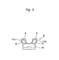
- FIG. 5 is a cross-sectional view of main parts illustrating the main body of the rail member of the shooting sliding device illustrated in FIG. 4 .
- the main body 8 is formed from a hollow building frame portion 10 having a rectangular cross-section, and rail portions 11 a and 11 b that obliquely stand to the outside of the building frame portion 10 from each of both end portions in a width direction of the building frame portion 10 and extend straightly from the stood leading end.
- the rail portions 11 a and 11 b are also hollow similarly to the building frame portion 10 , and are symmetrically disposed with respect to the center in the width direction of the building frame portion 10 .
- the first running surface 4 is formed to be recessed in a concave shape at the leading end portions of the rail portions 11 a and 11 b .
- the first running surface 4 formed on the rail portions 11 a and 11 b is disposed on the same plane.
- the second running surface 5 is an outer surface of the portion that obliquely stands from the building frame portion 10 in the rail portions 11 a and 11 b .
- the second running surface 5 is disposed so as to be tilted with respect to the first running surface 4 , and a tilt angle thereof is 45°.
- the tilt angle of the second running surface 5 with respect to the first running surface 4 is not limited to 45°, and may be an acute angle that is greater than 0° and less than 90°.
- the base 9 has two legs 12 extending so as to be tilted downward toward the outer side in the width direction of the main body 8 .
- An opening degree of the two legs 12 is adjustable.
- an adjuster 13 configured to adjust the horizontal installation of the shooting sliding device 1 is provided, the adjuster 13 has a bolt portion 14 , and the bolt portion 14 can go in and out at the leading end portion of the leg 12 .
- a lock nut 15 is provided at the leading end portion of the leg 12 , the bolt portion 14 of the adjuster 13 is freely rotatable with respect to the lock nut 15 , and the projection length from the leading end portion of the leg 12 can change by the rotation of the adjuster 13 .
- the lock nut 15 is not allowed the rotation of the adjuster 13 by being tightened. When loosening the lock nut 15 , the rotation of the adjuster 13 becomes possible.
- the slider 3 is provided with the main body 16 .
- the main body 16 is formed from a flat attachment surface portion 17 configured to attach the video camera or the camera platform, and a pair of support surface portions 18 a and 18 b extending from both end edges in the width direction of the attachment surface portion 17 .
- the support surface portions 18 a and 18 b are disposed to face each other.
- a male screw 19 to be engaged with the attaching female screw formed on the bottom surface portion of the video camera or the camera platform projects.
- skirt portions 20 a and 20 b extending obliquely outward in the width direction of the main body 16 are provided.
- the initial setting mechanism 7 is incorporated into the skirt portion 20 a of the support surface portion 18 a.
- FIG. 6 is a side view illustrating a slider of the shooting sliding device illustrated in FIG. 4 .
- FIGS. 7A , 7 B, and 7 C are a cross-sectional view taken along a line A-A of the slider illustrated in FIG. 3 , a cross-sectional view taken along a line B-B thereof, and a cross-sectional view taken along a line C-C thereof, respectively.
- the first bearing 6 extends from the attachment surface portion 17 between the support surface portions 18 a and 18 b , is rotatably attached to the ribs disposed in parallel to the support surface portions 18 a and 18 b by the shaft 21 , and is supported between the support surface portions 18 a and 18 b .
- the two first bearings 6 are disposed at both ends in the longitudinal direction of the main body 16 . Accordingly, the slider 3 is provided with total four first bearings 6 .
- the first bearing 6 is placed on the first running surface 4 of the rail member 2 and can run on the first running surface 4 .
- the second bearing 22 is rotatably attached to the skirt portions 20 a and 20 b of the support surface portions 18 a and 18 b by the shaft 23 , and the second bearing 22 is disposed inside the main body 16 .
- two second bearings 22 are disposed at both end portions in the longitudinal direction of the main body 16 , and the slider 3 is provided with total four second bearings 22 .
- the initial setting mechanism 7 is incorporated in the skirt portion 20 a of the slider 3 .
- the initial setting mechanism 7 is provided with an adjusting bolt 24 and a fixing bolt 25 .
- the adjusting bolt 24 can bring the second bearing 22 into contact with the second running surface 5 by screwing to increase the contact pressure thereof. Meanwhile, when loosening the adjusting bolt 24 , it is possible to reduce the contact pressure of the second bearing 22 to the second running surface 5 .
- the contact pressure of the second bearing 22 to the second running surface 5 due to the adjusting bolt 24 is adjusted to the extent that the second bearing 22 can smoothly run on the second running surface 5 .
- the fixing bolt 25 is screwed after adjusting the contact pressure of the second bearing 22 to the second running surface 5 due to the adjusting bolt 24 .
- the state adjusted to the contact pressure suitable for running is maintained by the fixing bolt 25 .
- the adjusting bolt 24 is disposed in parallel to the width direction of the skirt portion 20 a , and is disposed at the center in the longitudinal direction of the skirt portion 20 a .
- the fixing bolts 25 are arranged at a predetermined interval in the longitudinal direction of the skirt portion 20 a around the adjusting bolt 24 . Therefore, total two fixing bolts 25 are provided in the initial setting mechanism 7 .
- FIG. 8 is an exploded perspective view illustrating the slider illustrated in FIG. 6 from one support surface portion side.
- FIG. 9 is an exploded perspective view illustrating the slider illustrated in FIG. 6 from the other support surface portion side.
- the initial setting mechanism 7 is incorporated in the skirt portion 20 a of the slider 3 .
- the skirt portion 20 a extends to the opposite side to the attachment surface portion 17 , and has a fixing portion 60 which is bent so as to be disposed obliquely to the attachment surface portion 17 .
- the front of the fixing portion 60 has a flat surface 61 .
- a notch portion 62 is formed at the center in the longitudinal direction, and a contact pressure adjusting portion 63 having a female screw shape is provided in the notch portion 62 .
- the contact pressure adjusting portion 63 is intended to adjust the contact pressure of the second bearing 22 due to the adjusting bolt 24 .
- a screw portion 64 having a female screw shape is provided on both sides in the longitudinal direction of the fixing portion 60 with the notch portion 62 interposed therebetween.
- the skirt portion 20 a has a main body 65 to which the second bearing 22 is attached, and a projecting portion 66 which protrudes to the side on which the second bearing 22 is attached in the central portion of the main body 65 .
- the width of both ends of the longitudinal direction is enlarged, and the second bearing 22 is rotatably attached to each of both end portions by the shaft 23 .
- elongated holes 67 are formed in the width direction of the main body 65 , and the two elongated holes 67 can overlap the screw portion 64 of the fixing portion 60 .
- the width of the projecting portion 66 that is, the longitudinal length of the main body 65 is within the length of the notch portion 62 of the fixing portion 60 , and in the projecting portion 66 , a bolt insertion holes 68 capable of overlapping the contact pressure adjusting portion 63 of the fixing portion 60 are formed through the front and the back of the projecting portion 66 .
- the back as the flat surface of skirt portion 20 a is arranged to overlap the front of the main body 65 so that the two second bearings 22 are disposed on the outside in the longitudinal direction of the fixing portion 60 , respectively.
- the two elongated holes 67 of the main body 65 each overlap the two screw portions 64 of the fixing portion 60
- the projecting portion 66 is disposed inside the notch portion 62 of the fixing portion 60
- the bolt insertion hole 68 overlaps the contact pressure adjusting portion 63 .
- the adjusting bolt 24 is inserted into the bolt insertion hole 68 from the outside of the front of the projecting portion 66 and is screwed into the contact pressure adjusting portion 63 .
- the two fixing bolts 25 are each inserted into the inside of the two elongated holes 67 from the outside of the front of the main body 65 of the skirt portion 20 a and are screwed into the screw portions 64 .
- the main body 65 of the skirt portion 20 a is fixed to the fixing portion 60 by screwing of the fixing bolts 25 to the screw portions 64 , and the state adjusted to the contact pressure suitable for running of the second bearing 22 is maintained.
- the second bearing 22 is capable of running on the second running surface 5 by the adjusted contact pressure.
- a brake knob 26 is provided in a freely rotationally movable manner. As illustrated in FIG. 7C , the brake knob 26 has a brake shaft 27 , and the male screw 28 is cut on the front portion of the brake shaft 27 .
- the female screw 29 which allows the brake shaft 27 to move forward and backward is formed through the front and back, and the male screw 28 of the brake shaft 27 is screwed into the female screw 29 .
- the leading end portion of the brake shaft 27 comes into contact with and is pressed against the outer surface in the longitudinal direction of the rail portion 11 a of the rail member 2 by rotationally moving the brake knob 26 , and thus, the slider 3 is not able to slide along the rail member 2 . Meanwhile, when rotationally moving the brake knob 26 in the reverse direction to release the pressing force caused by the brake shaft 27 , the slider 3 is able to slide.
- a friction knob 30 is rotatably provided at the center in the longitudinal direction of the support surface portion 18 b disposed to face the support surface portion 18 a .
- the friction knob 30 has a first friction shaft 31 , and the male screw 28 is cut on the front portion of the first friction shaft 31 .
- the female screw 29 that allows the first friction shaft 31 to move forward and backward is formed through the front and back, and the male screw 28 of the first friction shaft 31 is screwed into the female screw 29 .
- a second friction shaft 32 capable of moving forward and backward in the longitudinal direction of the first friction shaft 31 is provided at the leading end portion of the first friction shaft 31 .
- the second friction shaft 32 is housed in a hollow portion 33 formed inside the first friction shaft 31 except for the leading end portion.
- the hollow portion 33 is formed from the leading end portion of the second friction shaft 32 to the friction knob 30 .
- a coil spring 34 is built in the hollow portion 33 , and the coil spring 34 freely expands and contracts between the friction knob 30 and the second friction shaft 32 .
- the leading end portion of the second friction shaft 32 comes into contact with the outer surface in the longitudinal direction of the rail portion 11 b .
- the coil spring 34 built in the hollow portion 33 contracts, and the elastic force is generated.
- the generated elastic force presses the outer surface of the rail portion 11 b via the leading end portion of the second friction shaft 32 , and thus, friction is generated.
- the magnitude of the friction can be adjusted by screwing condition of the first friction shaft 31 caused by the rotation of the friction knob 30 . For example, when increasing the sliding speed of the slider 3 , the friction can become smaller, and when decreasing the sliding speed, the friction can become larger. Furthermore, the occurrence of friction efficiently functions in adjusting the contact pressure of the second bearing 22 to the second running surface 5 due to the adjusting bolt 24 provided in the initial setting mechanism 7 , and facilitates the adjustment of the contact pressure.
- the support surface portion 18 b is provided with a level 35 adjacent to the friction knob 30 .
- the level 35 protrudes toward the outer side of the support surface portion 18 b.
- the shooting sliding device 1 as described above can not only be attached to the tripod 42 , but can be independently installed on the table.
- the rail member 2 two legs of the base 9 provided at both end portions in the longitudinal direction thereof are opened at an appropriate degree of opening legs, and the adjuster 13 located at the leading end portion of the leg 12 is disposed so as to abut against the front of the table.
- the first bearing 6 is mounted on the first running surface 4 , in the state that causes the friction to some extent by the rotation of the friction knob 30 , the brake knob 26 is rotationally moved, and the slider 3 is kept in a non-slidable state.
- the adjuster 13 is rotated so that the rail member 2 is horizontally arranged using the level 35 , and the rail member 2 is fixed by the lock nut 15 after adjust the length thereof, thereby completing the installation of the rail member 2 .
- the brake knob 26 is rotationally moved in the reverse direction, the slider 3 is made free, and thereafter, the second bearing 22 is moved toward and brought into contact with the second running surface 5 by the adjusting bolt 24 provided in the initial setting mechanism 7 , thereby adjusting the contact pressure.
- the fixing bolt 25 provided in the initial setting mechanism 7 is screwed to maintain the adjusted contact pressure. Adjustment and maintenance of the contact pressure between the second bearing 22 and the second running surface 5 as described above may be carried out either before or after attaching the video camera or the camera platform to the attachment surface portion 17 .
- the shooting sliding device 1 is provided with the rail member 2 that has the first running surface 4 and the second running surface 5 disposed so as to be tilted with respect to the first running surface 4 , and the slider 3 that has the first bearing 6 capable of running on the first running surface 4 and the second bearing 22 capable of running on the second running surface 5 .
- the linear slide of the slider 3 along the rail member 2 becomes more stable. Stability of the linear slide becomes obvious by the first bearings 6 and the second bearings 22 , and the total four first and second bearings are each provided.
- the slider 3 since the slider 3 has the initial setting mechanism 7 that moves the second bearing 22 forward and backward with respect to the second running surface 5 to adjust the contact pressure of the second bearing 22 to the second running surface 5 , the adjustment of the slide of the slider becomes easier.
- the adapter 36 for attachment to the tripod 42 is provided at the center of the building frame portion 10 of the rail member 2 .
- the adapter 36 has a first contact surface 37 capable of coming into contact with the building frame portion 10 of the rail member 2 , and a second contact surface 38 capable of coming into contact with the attachment portion 49 provided in the top portion 48 of the tripod 42 .
- the first contact surface 37 is a flat surface 39
- the second contact surface 38 has a curved surface 40
- the second contact surface 38 has a flat surface 41 in a portion that is disposed to face the first contact surface 37 .
- an attaching female screw 52 is embedded at the center of the attachment side of the tripod in the second contact surface 38 .
- the adapter 36 is a relatively thin member, the thickness thereof is suppressed within the height of the leg 12 , and the adapter has no member protruding from the second contact surface 38 , which does not impede the installation of the shooting sliding device 1 onto the table at all.
- female screws are cut at total three locations at the center of the building frame portion 10 of the rail member 2 and at both ends in the longitudinal direction.
- the male screw 53 standing from the first contact surface 37 is provided at the center of the first contact surface 37 of the adapter 36 .
- FIG. 10 is a perspective view illustrating a second exemplary embodiment of the tripod apparatus of the present invention.
- a tripod apparatus 71 the camera platform 43 is attached to the shooting sliding device 1 of the tripod apparatus 70 illustrated in FIG. 1 .
- a female screw (not illustrated) to be screwed to the male screw 19 provided in the attachment surface portion 17 of the main body 16 of the slider 3 is provided, and the camera platform 43 is attached and fixed to the slider 3 , by screwing the male screw 19 into the female screw.
- the attachment of the camera platform 43 has also become easier. Furthermore, since the tripod apparatus 71 is combined with the camera platform 43 , tilting and panning as well as the slide of the video camera also becomes possible, and a variety of shooting corresponding to the movement of the shooting target and the image as planned becomes possible.
- the tightening handle 44 illustrated in FIG. 2 can be shared with one used when directly attaching the camera platform 43 to the tripod 42 without attaching the shooting sliding device 1 .
- the shooting sliding device 1 can not only be horizontally disposed, but can be disposed so as to be tilted in a desired direction.
- the tripod apparatus of the present invention is not limited to the above-described embodiments. Various modifications can be made to the shape and the structure of the tripod, the shooting sliding device, and the tightening handle.
Applications Claiming Priority (2)
| Application Number | Priority Date | Filing Date | Title |
|---|---|---|---|
| JP2014-030346 | 2014-02-20 | ||
| JP2014030346A JP5564629B1 (ja) | 2014-02-20 | 2014-02-20 | 三脚装置 |
Publications (2)
| Publication Number | Publication Date |
|---|---|
| US20150233521A1 US20150233521A1 (en) | 2015-08-20 |
| US9243737B2 true US9243737B2 (en) | 2016-01-26 |
Family
ID=51417112
Family Applications (1)
| Application Number | Title | Priority Date | Filing Date |
|---|---|---|---|
| US14/328,134 Expired - Fee Related US9243737B2 (en) | 2014-02-20 | 2014-07-10 | Tripod apparatus |
Country Status (3)
| Country | Link |
|---|---|
| US (1) | US9243737B2 (ja) |
| JP (1) | JP5564629B1 (ja) |
| TW (1) | TWI530638B (ja) |
Cited By (17)
| Publication number | Priority date | Publication date | Assignee | Title |
|---|---|---|---|---|
| US9395031B1 (en) * | 2015-10-14 | 2016-07-19 | Gopro, Inc. | Camera mount |
| US10208889B2 (en) * | 2017-05-29 | 2019-02-19 | Tcg Partners, Llc—Intellectual Property Series | Collapsible three legged platform |
| USD841721S1 (en) | 2015-10-14 | 2019-02-26 | Gopro, Inc. | Camera mount |
| US20190317384A1 (en) * | 2018-04-11 | 2019-10-17 | Denisov Egor | Track System |
| US10474011B2 (en) | 2014-03-14 | 2019-11-12 | Really Right Stuff, Llc | Plate for camera equipment |
| US20200150514A1 (en) * | 2018-11-08 | 2020-05-14 | Shenzhen Youbaise Technology Co., Ltd. | Extended structure for use with a tripod |
| USD894256S1 (en) | 2018-08-31 | 2020-08-25 | Gopro, Inc. | Camera mount |
| USD905786S1 (en) | 2018-08-31 | 2020-12-22 | Gopro, Inc. | Camera mount |
| USD908165S1 (en) | 2018-12-31 | 2021-01-19 | David Craig Holland | Three-headed camera system |
| US20210033244A1 (en) * | 2019-07-30 | 2021-02-04 | Fourth Arrow, LLC | Mount for tree stand |
| US10928711B2 (en) | 2018-08-07 | 2021-02-23 | Gopro, Inc. | Camera and camera mount |
| USD928863S1 (en) | 2019-09-17 | 2021-08-24 | Gopro, Inc. | Camera light |
| US11429012B2 (en) | 2018-12-31 | 2022-08-30 | David Craig Holland | Audiovisual apparatus for simultaneous acquisition and management of coverage on production sets |
| US20230099957A1 (en) * | 2020-07-16 | 2023-03-30 | Zhongshan Dashan Photographic Equipment Co., Ltd. | Electrically controlled sliding apparatus for photographic equipment and locking assembly thereof |
| USD991318S1 (en) | 2020-08-14 | 2023-07-04 | Gopro, Inc. | Camera |
| USD997232S1 (en) | 2019-09-17 | 2023-08-29 | Gopro, Inc. | Camera |
| USD1023115S1 (en) | 2023-04-25 | 2024-04-16 | Gopro, Inc. | Camera mount |
Families Citing this family (7)
| Publication number | Priority date | Publication date | Assignee | Title |
|---|---|---|---|---|
| KR101650537B1 (ko) * | 2015-12-07 | 2016-09-23 | 주식회사 케이디앵글 | 슬라이더 조립체 |
| CN105782654A (zh) * | 2016-05-26 | 2016-07-20 | 李兴好 | 一种用于摄影机的新型云台 |
| CN108105548A (zh) * | 2018-01-31 | 2018-06-01 | 华北理工大学 | 一种移动拍摄云台 |
| US11474418B2 (en) * | 2020-03-11 | 2022-10-18 | Tilta Inc. | Camera mount system |
| CN111457221B (zh) * | 2020-04-03 | 2021-06-25 | 商丘师范学院 | 一种室内设计测绘装置 |
| CN113124274B (zh) * | 2021-04-23 | 2022-05-31 | 吉林师范大学 | 一种地理遥感测绘旋转装置 |
| KR102494935B1 (ko) * | 2022-06-14 | 2023-02-06 | 심플라온 주식회사 | 촬영장치의 팬틸트 구동장치용 틸트 보조 장치 및 이를 포함하는 촬영장치의 팬틸트 구동장치 |
Citations (17)
| Publication number | Priority date | Publication date | Assignee | Title |
|---|---|---|---|---|
| US3737130A (en) * | 1970-06-25 | 1973-06-05 | Slick Tripod Co Ltd | Hydraulically operated tripod head |
| US4952953A (en) * | 1989-06-28 | 1990-08-28 | Johan Ridderstolpe | Camera mounting arrangement |
| US6234690B1 (en) * | 1998-08-20 | 2001-05-22 | Frank Lemieux | Camera quick-release device |
| US6352228B1 (en) * | 1998-08-29 | 2002-03-05 | FLM GmbH Foto-, Licht-und Messtechnisches Zubehör | Tripod head |
| JP2005024442A (ja) | 2003-07-04 | 2005-01-27 | Meidensha Corp | ステレオ画像撮影装置 |
| US20070084979A1 (en) * | 2005-08-10 | 2007-04-19 | Sachtler Gmbh & Co. Kg | Camera tripod head |
| US20070090238A1 (en) * | 2005-10-20 | 2007-04-26 | Sdgi Holdings, Inc. | Bottom loading multi-axial screw assembly |
| US20090257741A1 (en) * | 2008-04-10 | 2009-10-15 | Camera Motion Research, Llc | Stabilizer Device for Optical Equipment |
| US20090315288A1 (en) * | 2008-06-23 | 2009-12-24 | Charles Hernandez | Dolly and track system |
| US7789356B1 (en) * | 2006-11-14 | 2010-09-07 | Jones Steven P | Stand assembly for an optical device |
| US7878123B2 (en) * | 2007-04-13 | 2011-02-01 | Jason Jackson | Single rail film dolly and slider |
| US7891888B2 (en) * | 2008-10-07 | 2011-02-22 | Dennis Wood | Camera slider system |
| US8021060B2 (en) * | 2007-06-11 | 2011-09-20 | Gitzo S.A. | Adjustable support head for optical or video/photographic equipment |
| US8534934B1 (en) * | 2012-06-14 | 2013-09-17 | Peter L. Carney | Camera stabilization device and method of use |
| US8721199B1 (en) * | 2013-06-07 | 2014-05-13 | Rhino Camera Gear, LLC | Slide-able mount for an image device |
| US20140161434A1 (en) * | 2012-12-06 | 2014-06-12 | Kadir Koymen | Slider support member |
| US8807496B2 (en) * | 2011-12-09 | 2014-08-19 | Kessler Crane, Inc. | Camera mount |
Family Cites Families (1)
| Publication number | Priority date | Publication date | Assignee | Title |
|---|---|---|---|---|
| JPS62179498U (ja) * | 1986-05-02 | 1987-11-14 |
-
2014
- 2014-02-20 JP JP2014030346A patent/JP5564629B1/ja not_active Expired - Fee Related
- 2014-06-03 TW TW103119185A patent/TWI530638B/zh not_active IP Right Cessation
- 2014-07-10 US US14/328,134 patent/US9243737B2/en not_active Expired - Fee Related
Patent Citations (17)
| Publication number | Priority date | Publication date | Assignee | Title |
|---|---|---|---|---|
| US3737130A (en) * | 1970-06-25 | 1973-06-05 | Slick Tripod Co Ltd | Hydraulically operated tripod head |
| US4952953A (en) * | 1989-06-28 | 1990-08-28 | Johan Ridderstolpe | Camera mounting arrangement |
| US6234690B1 (en) * | 1998-08-20 | 2001-05-22 | Frank Lemieux | Camera quick-release device |
| US6352228B1 (en) * | 1998-08-29 | 2002-03-05 | FLM GmbH Foto-, Licht-und Messtechnisches Zubehör | Tripod head |
| JP2005024442A (ja) | 2003-07-04 | 2005-01-27 | Meidensha Corp | ステレオ画像撮影装置 |
| US20070084979A1 (en) * | 2005-08-10 | 2007-04-19 | Sachtler Gmbh & Co. Kg | Camera tripod head |
| US20070090238A1 (en) * | 2005-10-20 | 2007-04-26 | Sdgi Holdings, Inc. | Bottom loading multi-axial screw assembly |
| US7789356B1 (en) * | 2006-11-14 | 2010-09-07 | Jones Steven P | Stand assembly for an optical device |
| US7878123B2 (en) * | 2007-04-13 | 2011-02-01 | Jason Jackson | Single rail film dolly and slider |
| US8021060B2 (en) * | 2007-06-11 | 2011-09-20 | Gitzo S.A. | Adjustable support head for optical or video/photographic equipment |
| US20090257741A1 (en) * | 2008-04-10 | 2009-10-15 | Camera Motion Research, Llc | Stabilizer Device for Optical Equipment |
| US20090315288A1 (en) * | 2008-06-23 | 2009-12-24 | Charles Hernandez | Dolly and track system |
| US7891888B2 (en) * | 2008-10-07 | 2011-02-22 | Dennis Wood | Camera slider system |
| US8807496B2 (en) * | 2011-12-09 | 2014-08-19 | Kessler Crane, Inc. | Camera mount |
| US8534934B1 (en) * | 2012-06-14 | 2013-09-17 | Peter L. Carney | Camera stabilization device and method of use |
| US20140161434A1 (en) * | 2012-12-06 | 2014-06-12 | Kadir Koymen | Slider support member |
| US8721199B1 (en) * | 2013-06-07 | 2014-05-13 | Rhino Camera Gear, LLC | Slide-able mount for an image device |
Cited By (35)
| Publication number | Priority date | Publication date | Assignee | Title |
|---|---|---|---|---|
| US11619866B2 (en) | 2014-03-14 | 2023-04-04 | Really Right Stuff, Llc | Plate for camera equipment |
| US10474011B2 (en) | 2014-03-14 | 2019-11-12 | Really Right Stuff, Llc | Plate for camera equipment |
| US11796897B2 (en) | 2014-03-14 | 2023-10-24 | Really Right Stuff, Llc | Plate for camera equipment |
| US11347137B2 (en) | 2014-03-14 | 2022-05-31 | Really Right Stuff, Llc | Plate for camera equipment |
| US11487191B2 (en) | 2014-03-14 | 2022-11-01 | Really Right Stuff, Llc | Plate for camera equipment |
| US20190133375A1 (en) * | 2014-10-23 | 2019-05-09 | TCG Partners LLC - Intellectual Property Series | Collapsible Three Legged Platform |
| US10791873B2 (en) * | 2014-10-23 | 2020-10-06 | Tcg Partners, Llc—Intellectual Property Series | Collapsible three legged platform |
| USD897415S1 (en) | 2015-10-14 | 2020-09-29 | Gopro, Inc. | Camera mount |
| US9772542B2 (en) | 2015-10-14 | 2017-09-26 | Gopro, Inc. | Camera mount |
| US10539858B2 (en) | 2015-10-14 | 2020-01-21 | Gopro, Inc. | Camera mount |
| US11029584B2 (en) | 2015-10-14 | 2021-06-08 | Gopro, Inc. | Camera mount |
| USD986946S1 (en) | 2015-10-14 | 2023-05-23 | Gopro, Inc. | Camera mount |
| USD841721S1 (en) | 2015-10-14 | 2019-02-26 | Gopro, Inc. | Camera mount |
| US9395031B1 (en) * | 2015-10-14 | 2016-07-19 | Gopro, Inc. | Camera mount |
| US10208889B2 (en) * | 2017-05-29 | 2019-02-19 | Tcg Partners, Llc—Intellectual Property Series | Collapsible three legged platform |
| US20190317384A1 (en) * | 2018-04-11 | 2019-10-17 | Denisov Egor | Track System |
| US10901303B2 (en) * | 2018-04-11 | 2021-01-26 | Denisov Egor | Track system |
| US10928711B2 (en) | 2018-08-07 | 2021-02-23 | Gopro, Inc. | Camera and camera mount |
| US11662651B2 (en) | 2018-08-07 | 2023-05-30 | Gopro, Inc. | Camera and camera mount |
| USD989165S1 (en) | 2018-08-31 | 2023-06-13 | Gopro, Inc. | Camera mount |
| USD905786S1 (en) | 2018-08-31 | 2020-12-22 | Gopro, Inc. | Camera mount |
| USD894256S1 (en) | 2018-08-31 | 2020-08-25 | Gopro, Inc. | Camera mount |
| US20200150514A1 (en) * | 2018-11-08 | 2020-05-14 | Shenzhen Youbaise Technology Co., Ltd. | Extended structure for use with a tripod |
| US11429012B2 (en) | 2018-12-31 | 2022-08-30 | David Craig Holland | Audiovisual apparatus for simultaneous acquisition and management of coverage on production sets |
| USD908165S1 (en) | 2018-12-31 | 2021-01-19 | David Craig Holland | Three-headed camera system |
| US20210033244A1 (en) * | 2019-07-30 | 2021-02-04 | Fourth Arrow, LLC | Mount for tree stand |
| USD1003979S1 (en) | 2019-09-17 | 2023-11-07 | Gopro, Inc. | Camera accessory mount |
| USD997232S1 (en) | 2019-09-17 | 2023-08-29 | Gopro, Inc. | Camera |
| USD928863S1 (en) | 2019-09-17 | 2021-08-24 | Gopro, Inc. | Camera light |
| US20230099957A1 (en) * | 2020-07-16 | 2023-03-30 | Zhongshan Dashan Photographic Equipment Co., Ltd. | Electrically controlled sliding apparatus for photographic equipment and locking assembly thereof |
| US11868031B2 (en) * | 2020-07-16 | 2024-01-09 | Zhongshan Dashan Photographic Equipment Co., Ltd. | Electrically controlled sliding apparatus for photographic equipment and locking assembly thereof |
| USD991318S1 (en) | 2020-08-14 | 2023-07-04 | Gopro, Inc. | Camera |
| USD1004676S1 (en) | 2020-08-14 | 2023-11-14 | Gopro, Inc. | Camera |
| USD1023115S1 (en) | 2023-04-25 | 2024-04-16 | Gopro, Inc. | Camera mount |
| USD1024165S1 (en) | 2023-05-17 | 2024-04-23 | Gopro, Inc. | Camera |
Also Published As
| Publication number | Publication date |
|---|---|
| TWI530638B (zh) | 2016-04-21 |
| JP2015155947A (ja) | 2015-08-27 |
| JP5564629B1 (ja) | 2014-07-30 |
| US20150233521A1 (en) | 2015-08-20 |
| TW201533368A (zh) | 2015-09-01 |
Similar Documents
| Publication | Publication Date | Title |
|---|---|---|
| US9243737B2 (en) | Tripod apparatus | |
| JP5568188B1 (ja) | 撮影用スライディング装置 | |
| US10871704B2 (en) | Gimbal | |
| US10533698B2 (en) | Locking device and gimbal having the locking device | |
| US9328998B2 (en) | Quick-detach accessory base mount for an accessory rail | |
| US20210156508A1 (en) | Dual clamping device | |
| KR101423596B1 (ko) | 볼헤드 잠금장치, 조절 장치 및 패널 장치 | |
| US10901303B2 (en) | Track system | |
| US9052573B2 (en) | Video camera motion stabilizing device | |
| JP6194444B2 (ja) | 雲台 | |
| EP3770480A1 (en) | Tripod head structure and gear adjustment mechanism thereof | |
| EP3462075A1 (en) | A connecting device and a gimbal apparatus | |
| US20170293206A1 (en) | Adjustable Support Arm for Use Between Camera and Camera Support | |
| US20070152116A1 (en) | Ball head | |
| US10845679B2 (en) | Quick connection handle for photographic equipment and photographic equipment assembly | |
| US9213222B2 (en) | Control arm for an imaging device | |
| JP2005521844A (ja) | 一般に装置のための、特に光学装置または写真装置などのための支持体 | |
| US20110297809A1 (en) | Projector mount with micro adjustment | |
| CN106337997B (zh) | 一种可调拍摄云台 | |
| KR20070079116A (ko) | 산업 및 삼각대용 다용도 볼 헤드 | |
| KR20080113787A (ko) | 각도 조절장치 | |
| JP3124756U (ja) | カメラ位置決め具 | |
| KR20150139220A (ko) | 삼각대용 볼헤드 | |
| KR200188035Y1 (ko) | 산업 및 삼각대용 다용도 볼헤드 |
Legal Events
| Date | Code | Title | Description |
|---|---|---|---|
| AS | Assignment |
Owner name: HEIWA SEIKI KOGYO CO., LTD., JAPAN Free format text: ASSIGNMENT OF ASSIGNORS INTEREST;ASSIGNOR:HIDA, NOBUYUKI;REEL/FRAME:033289/0950 Effective date: 20140627 |
|
| STCF | Information on status: patent grant |
Free format text: PATENTED CASE |
|
| MAFP | Maintenance fee payment |
Free format text: PAYMENT OF MAINTENANCE FEE, 4TH YEAR, LARGE ENTITY (ORIGINAL EVENT CODE: M1551); ENTITY STATUS OF PATENT OWNER: LARGE ENTITY Year of fee payment: 4 |
|
| FEPP | Fee payment procedure |
Free format text: MAINTENANCE FEE REMINDER MAILED (ORIGINAL EVENT CODE: REM.); ENTITY STATUS OF PATENT OWNER: LARGE ENTITY |
|
| LAPS | Lapse for failure to pay maintenance fees |
Free format text: PATENT EXPIRED FOR FAILURE TO PAY MAINTENANCE FEES (ORIGINAL EVENT CODE: EXP.); ENTITY STATUS OF PATENT OWNER: LARGE ENTITY |
|
| STCH | Information on status: patent discontinuation |
Free format text: PATENT EXPIRED DUE TO NONPAYMENT OF MAINTENANCE FEES UNDER 37 CFR 1.362 |
|
| FP | Lapsed due to failure to pay maintenance fee |
Effective date: 20240126 |