US9227017B2 - Automatic mixing device and delivery system - Google Patents
Automatic mixing device and delivery system Download PDFInfo
- Publication number
- US9227017B2 US9227017B2 US13/529,757 US201213529757A US9227017B2 US 9227017 B2 US9227017 B2 US 9227017B2 US 201213529757 A US201213529757 A US 201213529757A US 9227017 B2 US9227017 B2 US 9227017B2
- Authority
- US
- United States
- Prior art keywords
- mixing
- wet
- medicament
- automatic injection
- assembly
- Prior art date
- Legal status (The legal status is an assumption and is not a legal conclusion. Google has not performed a legal analysis and makes no representation as to the accuracy of the status listed.)
- Active, expires
Links
Images


Classifications
-
- A—HUMAN NECESSITIES
- A61—MEDICAL OR VETERINARY SCIENCE; HYGIENE
- A61M—DEVICES FOR INTRODUCING MEDIA INTO, OR ONTO, THE BODY; DEVICES FOR TRANSDUCING BODY MEDIA OR FOR TAKING MEDIA FROM THE BODY; DEVICES FOR PRODUCING OR ENDING SLEEP OR STUPOR
- A61M5/00—Devices for bringing media into the body in a subcutaneous, intra-vascular or intramuscular way; Accessories therefor, e.g. filling or cleaning devices, arm-rests
- A61M5/178—Syringes
- A61M5/20—Automatic syringes, e.g. with automatically actuated piston rod, with automatic needle injection, filling automatically
- A61M5/2066—Automatic syringes, e.g. with automatically actuated piston rod, with automatic needle injection, filling automatically comprising means for injection of two or more media, e.g. by mixing
-
- A—HUMAN NECESSITIES
- A61—MEDICAL OR VETERINARY SCIENCE; HYGIENE
- A61J—CONTAINERS SPECIALLY ADAPTED FOR MEDICAL OR PHARMACEUTICAL PURPOSES; DEVICES OR METHODS SPECIALLY ADAPTED FOR BRINGING PHARMACEUTICAL PRODUCTS INTO PARTICULAR PHYSICAL OR ADMINISTERING FORMS; DEVICES FOR ADMINISTERING FOOD OR MEDICINES ORALLY; BABY COMFORTERS; DEVICES FOR RECEIVING SPITTLE
- A61J1/00—Containers specially adapted for medical or pharmaceutical purposes
- A61J1/14—Details; Accessories therefor
- A61J1/20—Arrangements for transferring or mixing fluids, e.g. from vial to syringe
- A61J1/2093—Containers having several compartments for products to be mixed
-
- A—HUMAN NECESSITIES
- A61—MEDICAL OR VETERINARY SCIENCE; HYGIENE
- A61M—DEVICES FOR INTRODUCING MEDIA INTO, OR ONTO, THE BODY; DEVICES FOR TRANSDUCING BODY MEDIA OR FOR TAKING MEDIA FROM THE BODY; DEVICES FOR PRODUCING OR ENDING SLEEP OR STUPOR
- A61M5/00—Devices for bringing media into the body in a subcutaneous, intra-vascular or intramuscular way; Accessories therefor, e.g. filling or cleaning devices, arm-rests
- A61M5/178—Syringes
- A61M5/20—Automatic syringes, e.g. with automatically actuated piston rod, with automatic needle injection, filling automatically
- A61M5/2033—Spring-loaded one-shot injectors with or without automatic needle insertion
-
- A—HUMAN NECESSITIES
- A61—MEDICAL OR VETERINARY SCIENCE; HYGIENE
- A61M—DEVICES FOR INTRODUCING MEDIA INTO, OR ONTO, THE BODY; DEVICES FOR TRANSDUCING BODY MEDIA OR FOR TAKING MEDIA FROM THE BODY; DEVICES FOR PRODUCING OR ENDING SLEEP OR STUPOR
- A61M5/00—Devices for bringing media into the body in a subcutaneous, intra-vascular or intramuscular way; Accessories therefor, e.g. filling or cleaning devices, arm-rests
- A61M5/178—Syringes
- A61M5/24—Ampoule syringes, i.e. syringes with needle for use in combination with replaceable ampoules or carpules, e.g. automatic
- A61M5/2448—Ampoule syringes, i.e. syringes with needle for use in combination with replaceable ampoules or carpules, e.g. automatic comprising means for injection of two or more media, e.g. by mixing
-
- B—PERFORMING OPERATIONS; TRANSPORTING
- B65—CONVEYING; PACKING; STORING; HANDLING THIN OR FILAMENTARY MATERIAL
- B65B—MACHINES, APPARATUS OR DEVICES FOR, OR METHODS OF, PACKAGING ARTICLES OR MATERIALS; UNPACKING
- B65B29/00—Packaging of materials presenting special problems
- B65B29/10—Packaging two or more different substances isolated from one another in the package but capable of being mixed without opening the package, e.g. forming packages containing a resin and hardener isolated by a frangible partition
-
- A—HUMAN NECESSITIES
- A61—MEDICAL OR VETERINARY SCIENCE; HYGIENE
- A61M—DEVICES FOR INTRODUCING MEDIA INTO, OR ONTO, THE BODY; DEVICES FOR TRANSDUCING BODY MEDIA OR FOR TAKING MEDIA FROM THE BODY; DEVICES FOR PRODUCING OR ENDING SLEEP OR STUPOR
- A61M5/00—Devices for bringing media into the body in a subcutaneous, intra-vascular or intramuscular way; Accessories therefor, e.g. filling or cleaning devices, arm-rests
- A61M5/178—Syringes
- A61M5/20—Automatic syringes, e.g. with automatically actuated piston rod, with automatic needle injection, filling automatically
- A61M2005/2073—Automatic syringes, e.g. with automatically actuated piston rod, with automatic needle injection, filling automatically preventing premature release, e.g. by making use of a safety lock
-
- F—MECHANICAL ENGINEERING; LIGHTING; HEATING; WEAPONS; BLASTING
- F04—POSITIVE - DISPLACEMENT MACHINES FOR LIQUIDS; PUMPS FOR LIQUIDS OR ELASTIC FLUIDS
- F04C—ROTARY-PISTON, OR OSCILLATING-PISTON, POSITIVE-DISPLACEMENT MACHINES FOR LIQUIDS; ROTARY-PISTON, OR OSCILLATING-PISTON, POSITIVE-DISPLACEMENT PUMPS
- F04C2270/00—Control; Monitoring or safety arrangements
- F04C2270/04—Force
- F04C2270/042—Force radial
- F04C2270/0421—Controlled or regulated
Definitions
- the present embodiments relate generally to auto-injectors and more particularly to wet/dry mixing auto-injectors, prefilled syringes and reconstitution devices.
- a mixing and/or automatic injection device having an interior chamber containing a wet component that may be pH optimized to be mixed with a dry component contained in a mixing assembly.
- the wet component being confined or sealed in the interior chamber by a seal or valve, where upon activation of the seal or valve the wet interior chamber becomes in fluid communication with the mixing assembly and dissolution of the dry component into the wet component occurs.
- the mixing assembly can contain at least one fluidic conduit, for example at least one fluidic channel. In some embodiments, the mixing assembly contains at least one microfluidic channel.
- the mixing assembly is also configured to transfer the dissolved or reconstituted wet and dry components into a needle assembly or other delivery assembly configured to inject or deliver said components into a person or animal.
- FIGS. 1A-I illustrate an embodiment and various configurations of a wet/dry mixing auto-injector.
- FIGS. 2A-F illustrate various embodiments of a mixing assembly.
- FIGS. 3A-G illustrate various microfluidic channel configurations for use in a mixing assembly.
- aspects and embodiments described herein relate generally to the field of auto-injector devices, prefilled syringes and reconstitution devices.
- the following application describes an auto-injector and wet/dry mixing device configured to mix a dry and wet components of a medicament forming a solution to be injected into a person.
- This auto-injector device and mixing device is accomplished by integrating a mixing device assembly having at least one microfluidic channel into an auto-injector device with a pre-loaded charge or energy source such as one embodiment illustrated in FIG. 1A .
- Some of the advantages of the mixing device assembly and auto-injector device embodiments described herein include compact size, mixing consistency, mixing speed, mixing control, eliminating shaking or swirling, increasing portability, filtering particulates. It also enables the use of dry medicaments, which allow for continued potency in broader temperature ranges.
- a medicament may refer to any of a drug, medication, antidote, vaccine, protein, compound or other chemical substance.
- Medicaments may be formed of, or separated into multiple components such as wet and dry components that may be combined, reconstituted, or dissolved into one another to form a solution where the dry component or concentrated solution is soluble, partially soluble, or even non-soluble in the specified diluent and the wet component, solvent or solution, which dissolves or transports the active pharmaceutical dry component. This may be accomplished through solubility, pH, or other physical or chemical means.
- a medicament as described herein includes, but is not limited to, a dry form of epinephrine or adrenaline configured to dissolve into a solvent or solution through solubility, pH, or other physical or chemical means.
- Exposure to certain substances can cause allergic reactions in some individuals. Such allergic reactions can lead to anaphylactic shock. This may also cause reactions such as a sharp drop in blood pressure, hives, and/or severe airway constriction, which may result in a life-threatening condition. Responding rapidly to mitigate the effects from such exposures may decrease chances for patient injury and/or death. For example, in certain situations, an injection of epinephrine (i.e., adrenaline) may provide substantial and/or complete relief from the allergic reaction. In other situations, an injection of an antidote to a toxin may greatly reduce and/or eliminate the harm potentially caused by the toxin exposure. Because emergency medical facilities may not be available when an individual is suffering from an allergic reaction or toxin exposure, some individuals carry a medicament delivery device, such as, an auto-injector, to rapidly self-administer a medicament to mitigate the reaction and/or effects.
- a medicament delivery device such as, an auto-injector
- the epinephrine and/or medicaments stored in auto-injectors as a liquid until ready for use may suffer from certain shelf-life limitations and temperature, light, and oxygen exposure limitations and have a limited lifetime over which they are acceptably effective. Beyond that acceptable lifetime, these medicaments may degrade and lose an unacceptable amount of potency.
- degradation of epinephrine and/or other medicaments may be accelerated when subjected to large temperature excursions, especially when the temperature exceeds its acceptable storage temperature.
- some manufacturers recommend that an epinephrine auto-injector be stored at a controlled room temperature (20° C.-25° C. with allowable temperature excursions as low as 15° C.
- the epinephrine may remain stable for up to 20 months from the date of manufacture, even though the manufacturer suggests the epinephrine and/or auto-injector be replaced after approximately 12 months of patient ownership, at a maximum. Any deviation of the epinephrine and/or auto-injector outside of this recommended temperature range will cause the epinephrine to lose potency possibly rendering the epinephrine ineffective more rapidly.
- This temperature, oxygen, material contact, compound instability, and/or light-induced degradation problem spans many liquid medicaments and markets in addition to epinephrine like Benadryl®, atropine, glucagon, butyrylcholinesterase, phinothiazemes, haloperidol, clozapine, fluphenazine, benzo diazepines, carbamazepines, nytroglycerin well as other small molecule and large molecule compounds.
- Potential markets served by this invention are allergies, psychotics, epilepsy, nerve agent antidotes, hypoglycemia, diabetes, chemical or biological warfare antidotes, migraines, pain killers, traumatic brain injury, dehydration, cardiac care, asthma, scurvy, small pox, or flu.
- Maintaining the mandated storage environment for the medicament auto-injector may present a challenge for individuals not always carrying a temperature-controlled environment or near one. Often, individuals will keep epinephrine-filled auto-injectors in multiple temperature-controlled environments as a precautionary measure. However, an allergic reaction may occur physically distant from the nearest auto-injector. For example, bee stings, are more likely to occur outside than indoors. Food containing peanuts are more likely to be supplied to the individual away from a controlled home environment like at a baseball park. Emergency intervention required after a soldier is exposed to a chemical and/or biological toxin in the field, is also not likely to occur in a temperature-controlled environment. Merely placing an auto-injector in a purse, backpack, car and so forth is likely to encounter temperature excursions/fluctuations, outside of the recommended stabilized temperature range on a hot summer's day.
- One method of increasing the shelf life of medicaments is to freeze dry (lyophilize) and/or spray dry or vacuum dry and put them into dry and/or powdered form. This is, for example, done when shipping vaccines and/or other medicaments to countries where cold chain infrastructure is poorly implemented. Dry medicaments are then reconstituted into liquid form just prior to being dispensed into a syringe and injected into a patient. This helps to ensure that the medicament is fresh and potent.
- FIGS. 1A-F One embodiment of an auto-injector device containing a dry and/or powdered medicament (“dry component”) that is kept separate from the diluents (“wet component”) is illustrated in FIGS. 1A-F .
- dry component a dry and/or powdered medicament
- wet component a dry and/or powdered medicament
- FIGS. 1A-F One embodiment of an auto-injector device containing a dry and/or powdered medicament (“dry component”) that is kept separate from the diluents (“wet component”) is illustrated in FIGS. 1A-F .
- dry component dry and/or powdered medicament
- wet component dry component that is kept separate from the diluents
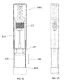
- FIG. 1A A perspective view of an embodiment of a wet/dry mixing auto-injector 100 a in a stored state is illustrated in FIG. 1A .
- a front panel or side is removed to show the internal components of the auto-injector 100 a .
- a housing 102 contains a pre-loaded spring 112 applying a force to mixing assembly 110 , which is held firmly in place by a releasable latch 116 .
- Extending from the mixing assembly 110 is a needle 108 , which is partially contained in needle guide 106 .
- a cap 104 is connected to safety shims 120 and may be separated from housing 102 by pulling cap 104 away from housing 102 .
- Posts 114 are positioned near releasable latches 116 to spread the latches apart, which in turn allow the pre-loaded spring 112 to cause the mixing and needle assembly to move.
- a front view of the auto-injector 100 a in storage mode with a removed front panel or side is illustrated in FIG. 1B .
- FIGS. 1C-D illustrates a wet/dry mixing auto-injector 100 c where the cap and safety shim portion is being removed 126 to expose a gap 122 between the releasable latches 116 and the internal sides of housing 102 , thus allowing for triggering mechanism 124 to be depressed (See FIGS. 1E-F ).
- Triggering mechanism 124 may be attached or push up against releasable latches 116 causing them to spread apart around posts 114 , thus releasing the stored energy in spring 112 to propel forward mixing assembly 110 with needle 108 through the needle guide 106 .
- Stored energy sources may include compressed springs, compressed gas chambers, electric power or other storable energy sources known in the art.
- FIGS. 1E-F illustrates wet/dry mixing auto-injector 100 d where triggering mechanism 124 may be depressed or pushed 128 toward housing 102 .
- triggering mechanism 124 may be depressed or pushed 128 toward housing 102 .
- One such scenario includes a person holding housing 102 in a hand and pressing or jamming triggering mechanism 126 against a leg. Again by pressing the triggering mechanism 124 , releasable latches 116 are spread apart by posts 114 releasing the energy stored in spring 112 to force the mixing assembly 110 forward with needle 106 injecting into the leg.
- FIGS. 1G-H illustrate a the wet/dry mixing auto-injector 100 g (in a triggered or fired state) with the needle 108 and exposed end 109 extended through needle guide 106 outside of housing 102 , which may be injected into a person.
- the mixing assembly in some embodiments is comprised of a collapsible bulb containing a wet component. When the collapsible bulb is pressed against an inner side wall of housing 102 , pressure builds inside the bulb to burst a seal separating the wet component in the bulb from a mixing device containing in part a dry component. Mixing then automatically occurs in the mixing device between the wet and dry components into a solution, which is then forced into needle 108 and into a person.
- FIG. 1I illustrates a configuration of the wet/dry mixing auto-injector 100 i having its cap 104 being reinserted 140 into the housing 102 . This now allows the exposed needle 108 to be covered for safe handling.
- FIGS. 2A-C illustrate various views of a wet/dry mixing assembly 110 comprised of a mixing device 152 , seal 154 , wet component storage cavity 150 contained within collapsible bulb 158 . Also shown in these views is a homogenization zone 156 that allows for the mixed wet and dry components to further homogenize prior to entering the needle 108 .
- This homogenizing zone which helps to remove any concentration gradients that may occur during the mixing process, is not required in all embodiments and may take many forms. For example, in one configuration that is devoid of a homogenizing zone the entrance orifice to the needle may be on the side of the needle, which is directly in fluid communication of the mixing device 152 .
- a force such as a pre-loaded spring may act on the collapsible bulb creating a force on the seal separating the wet component from dry component contained within a portion of the mixing device.
- the seal may burst or open or move or change in some way, allowing the wet and dry components to be mixed in the mixing device.
- a delivery assembly devoid of a needle is configured similarly to deliver the mixed solution into a person or animal. This may be accomplished through an IV that is already inserted, through the mouth, by pressure through the skin and so forth.
- MEMS micro-electrical-mechanical system
- FIGS. 2D-F illustrate various views of a multiple wet/dry component mixing assembly 170 comprised of a mixing device 153 having multiple conduits or channels, seal 154 , wet component storage cavities 150 a - b contained within a collapsible bulb 158 and homogenization zone 156 .
- Mixing assembly 170 allows for two different types of medicaments (or two doses of the same) to be mixed and inserted into a person using a single needle or other delivery system.
- seal 154 spans the orifices of each storage cavity 150 a - b , which are each in fluid communication with a different channel contained within the mixing device 153 . These channels may vary in length and size enabling a time mixing/release of each medicament.
- a first wet component stored in 150 a enters a unique channel(s) that have a pathway shorter than the unique channel(s) the second wet component stored in 150 b are in fluid communication with.
- the first wet component mixes with the first dry component, homogenizes (in this embodiment, but not all embodiments), enters the needle assembly and is injected into a person, where the second wet component takes longer to mix with the second dry component and follows after the first mixed medicament has entered the needle assembly to be injected into the person after.
- This is useful for two medicaments that are not compatible to be stored in the same portions of the mixing assembly and/or reconstituted or mixed together in the same channel.
- Mixing assembly 170 may be used with a single pre-loaded force, multiple pre-loaded forces and a single delivery system.
- Microfluidic devices or systems enable control and manipulation of fluids at very small scales. At sub-centimeter and/or sub-millimeter dimensions, the role of interfaces starts to become dominate and surface tension, fluidic resistance and such begin to control behavior, which may respond differently than macroscopic properties of fluid flow. Mixing can be accomplished with systems similar to the one drawn in FIGS. 3A-B .
- a main flow channel 302 is machined, for example, in glass or polymer with a series of “herringbone” or other type of grooves 304 , which create an environment causing the flow of material through the channel to be chaotic as opposed to laminar. This chaotic flow creates a series of eddy's or vortices inside the channel, which function to stir or mix and dissolve dry components into the wet component forming a solution.
- Embodiment 300 a may be made of two parts, such as machined portion 312 where the main channel 302 and grooves 304 having an alternating pattern (these grooves may also be randomized) are all formed therein.
- 312 may be constructed of machined glass or an injection molded polymer.
- a base 310 that is a flat glass or polymer is then attached to 312 enclosing the main channel 302 .
- the cross-sectional view of embodiment 300 b has the manufactured portion 312 having both the main channel 302 and grooves 304 formed therein, which is attached to a base 310 . Chaotic flow here is illustrated by 306 .
- the flow channel may be constructed to widen and narrow or bulb/bulge along one side, two sides or around the entire cross-section of the channel.
- FIG. 3C illustrates a flow channel having multiple bulbs 314 integrated into the main flow channel 302 , which help to break up laminar flow and cause chaotic flow behavior.
- the bulbs 314 are shown to be on the top and bottom of the channel, but may also be formed around the entire cross-section of main channel 302 .
- FIG. 3D illustrates a micro-channel that gets wider and smaller, which also may be useful in converting laminar flow to chaotic flow within the flow channel.
- the main channel 302 is initially smaller in width and then expands in width to a swell 316 .
- Swell 316 in other configurations may act as a reservoir or well and have larger amounts of dry component stored therein. Again swell 316 may be a larger pocket or open area in which smaller structures may be placed within, the swell and any contained structures therein help cause disruption of flow. Swells or wells may be placed strategically through a micro-channel system to create mixing.
- serpentines Another way of creating chaotic flow and mixing is to introduce bends or turns into the micro-channel(s) of the mixing device such as using a serpentine channel shown in FIGS. 3E-F rather than a straight channel, varying width or herringbone design.
- These serpentines have two functions. First, they enable miniaturization of the plumbing by bending the fluid flow direction so that the channel can double back, thus a longer channel more efficiently utilizes a smaller area. Second, natural flow becomes disrupted every time there is a bend or elbow in the channel, which results in mixing.
- These serpentine meanders can be designed so there are soft turns 320 that snake back and forth (shown in embodiment 300 e ), or they can be designed with sharp 90 degree bends 300 , which is shown in 300 f .
- each of these microfluidic embodiments 300 e - f each is comprised of single channel having an opening 324 , 334 to receive a wet component after the seal has been activated to an open or mixing state and an exit 326 , 336 configured to be in fluid communication with a needle assembly or an in-between homogenization region.
- a straight microfluidic channel configured with parallel walls may be sufficient to mix wet and dry components. Dry components stored inside a portion of the microfluidic channel may act to break up the laminar flow within the channel and create chaotic mixing. When the liquid moves through the channel and begins to push into the dry component contained in a portion therein, the flow front will cause natural turbulence or chaotic flow that focuses the flow towards the center of the channel and then causes the liquid to double back in the reverse direction near the channel wall. In order to make this happen, the channel dimension, which, in one embodiment can be defined by a square cross-section, should be below a certain size.
- one or both sides of the channel cross-section may have a dimension less than 2 mm, or between 1 mm and 2 mm, or less than 1 mm, or between 500 um and 1 mm, or less than 500 um, or between 250 um and 500 um, or less than 250 um, or between 100 um and 250 um, or less than 100 um, or between 50 um and 100 um, or less than 50 um, or between 10 um and 50 um, or less than 10 um, or between 1 um and 10 um, or less than 1 um.
- channels having a channel with a cross-sectional dimension less than 1 um are considered to be nanofluidic and have their respective set of properties for mixing medicaments.
- the dimensions of the grove-like-cuts are defined in a model which is in the public domain and published in Whitesides et al., Science, V295, 2002.
- Channel cross-section shapes include but are not limited to circular, elliptical, square, rectangular, and so forth.
- the single channel serpentine microfluidic configurations for a mixing device shown in FIGS. 3E-F are generally constructed in a planar configuration comprising of a long channel where most of the bends occur in a single plane.
- a non-planar microfluidic channel configuration where the microfluidic channel(s) may be positioned with bends and flow direction in multiple planes is contemplated.
- Another multi-dimensional configuration includes using a microfluidic channel that is not confined in a rigid space, such as a bendable or flexible tube that may be repositioned or move as fluid passes through, which also may assist in the mixing process.
- FIG. 3 illustrates a mixing channel 300 g having an opening 344 leading around a bound into a well or larger interior portion of the channel where internal structures such as posts 350 are contained therein to facilitate chaotic flow and mixing.
- channel 300 g funnels back into an exit/opening 346 .
- the posts may be on the nano-scale in size or even the micro-scale in size.
- Various internal patterns and shapes assist in causing chaotic flow and mixing.
- Some channels may include multiple portions having internal structures.
- mixing may also be accomplished with active assistance from additional forces like electric fields, magnetic fields, acoustics and such.
- a voltage can act on a charged solution or electric-double-layers that form at the interface between the channel sidewall and the fluid itself. This voltage can be used to cause mixing.
- Manufacturing a mixing device may be done in a variety of ways.
- One common way is with SU8 lithography and PDMS.
- SU8 2100 series from Microchem is spun on a wafer and baked at 65 C for 5 min and then at 95 C for 20 min on a hotplate. The substrate is removed from hotplate and allowed to cool.
- Photolithography is done by exposing the SU8 through a mask of the desired pattern at 540 mJ/cm2. The exposed SU8 is then baked at 65 C for 10 min and 95 C for 5 min. Once this is done the wafer is cooled and developed in PGMEA for 10 min. Once the pattern has been revealed, this can be used as a master from which to replicate microfluidic channels in silicone or PDMS.
- PDMS is mixed with a curing agent and then cast on top of the master fabricated in SU8. It is good to silinize the master for up to 3 hours using 1H, 1H, 2H, 2H-Perfluorooctytrichlorosilane before casting the PDMS to ensure good release.
- the PDMS is mixed and cast it is put into a vacuum to remove the bubbles and then placed into a drying oven at 65 C for more than 5 hours. Once drying is finished it can be peeled from the master and bonded to another block of PDMS or glass. This bond may be made by activating both surfaces with an oxygen plasma. It may be necessary to make holes in the PDMS or glass in order to create inlets and outlets for fluid flow.
- microfluidic fabrication can be demonstrated by machining into glass. Again, photolithography can be used to define a pattern and then dry and/or wet etching processes like reactive ion etching or hydrofluoric acid respectively can be used to transfer the pattern into the glass. Ultrasonic machining and direct write using a laser is another way to make these channels in glass substrates. Once the channels are machined into a piece of glass, a complete and sealed glass mixing device can be fabricated by bonding two glass parts together using a process called fusion bonding.
- Another embodiment of the fabrication can be done using injection molded plastics and/or other methods of shaping plastic parts like embossing.
- the plastic mixing devices may be sealed to either glass or other plastics using a variety of techniques including thermal sealing, sonic welding or epoxy.
- the dry component may be stored in a variety of locations inside or outside the mixing device including in chamber(s), pocket(s), a portion of the micro-channel(s).
- the dry component is placed into the mixing device wet and subsequently dried.
- epinephrine or another medicament is dispensed into the device wet, lyophilization or some other controlled drying technique is performed to dry the epinephrine component inside the mixing device where it resides in a more stable state until a wet component enters therein and mixing, dissolution or reconstitution begin.
- the wet component When manufacturing the injection or mixing device the wet component may be inserted into the mixing assembly, but confined or sealed off in a separate region, blister, chamber, vial, collapsible bulb by a seal, valve or other temporary restraining mechanism until it is ready to be activated, mixed with the dry component and used or injected into a person or animal. In this separation state, as mentioned the components are able to have an increased shelf-life and/or temperature exposure range. Upon activation, the mixing of the wet and dry components would take place inside the mixing assembly before injecting or dispensing the drug inside the individual.
- dry component adding techniques may be used in the microfluidic channels, swells, homogenization zones and other areas within the mixing assembly.
- multiple dry components may be inserted or contained in the mixing assembly.
- a first dry component may aid in dissolving with the second dry component after it is dissolved or partially dissolved with the wet component.
- multiple wet chambers, each with a different wet component may incorporated into the automatic injection device.
- Some formulations of wet and dry components include, but are not limited to, one or more therapeutic compounds (e.g., adrenaline) dissolved in an appropriate solvent.
- the solvent is an aqueous solution.
- the aqueous solution can be water alone, or can include one or more buffers, salts, and/or other components.
- the pH and/or salt concentration of the solvent can be optimized for solubilizing the therapeutic compound(s).
- the solvent is or includes an organic solvent (e.g., an alcohol).
- the dry component may also be any dry form of a medicament including the base and any salt forms.
- free base epinephrine as well as any epinephrine salts including: HCl, maleate, malate, fumarate, bitartrate, acid tartrate, hydrogen tartrate, and other salts may be used as the dry component.
- the barrier or seal serves to prevent un-intentional mixing and/or humidity from the surrounding environment from penetrating the dry storage and degrading the medicament.
- a spring and/or mechanical arm and/or pressure and/or some type of flow will push through the barrier and/or break the barrier and/or the barrier will move and/or change in some way to allow the wet liquid component to interact with the dry resulting in the dry component becoming soluble and/or dissolving in the wet component.
- a barrier separating the wet component from the mixing assembly containing an orifice, o-ring, and/or separating barrier made of a material such as, rubber.
- a secondary mechanism may be activated, thus causing the two components to move through the mixing device so that sufficient, complete, uniform, and/or homogeneous mixing takes place.
- the applied force causes the freshly mixed solution through the needle, syringe, and/or other delivery mechanism, which results in the drug entering the body of a human or non-human.
- This configuration may be used where the dry component is stored in a chamber or pocket prior to entering a microfluidic channel or within a portion of the microfluidic channel(s) itself.
- microfluidic pumps based on electro-osmotic flow and or piezoelectric pumps to serve as the mechanism by which the fluid is driven into and/or out of the mixing device and/or needle.
- the blister can either be separate or incorporated into the plastic or glass of the mixing device.
- the blister commonly consists of a round, fluid-containing pocket with one stiff face and a flexible bulged membrane.
- the bulged membrane commonly is formed of a multiple layer laminate that includes an entrained metallic layer to decrease the rate of long-term moisture transport out of the blister. This metallic layer would not be in direct contact with the medicament.
- the stiff face may be solid or contain a membrane designed to allow for the exfiltration of the blister's entrained fluid upon a certain pressure being attained.
- the blister is pressurized and/or collapsed by actuating the blister by electrical and/or mechanical and/or chemical, and/or thermal means.
- This pressure and/or applied force is sufficient to cause the controlled evacuation of the blister and allow the contained fluid to move within the device to where it is used and/or mixed.
- the actuation may be accomplished by the use of a memory metal such as Nitinol to actuate the bulged membrane and generate sufficient pressure to evacuate the blister and move that fluid through subsequent dry drug components and mixing structures.
- Other actuating devices such as linear actuators and motors may be used to actuate the blister.
- the device may be either powered by an electro-chemical storage device such as a capacitor or battery and/or a mechanical storage device such as a compression or torsion spring. If the device is powered by an electro-chemical storage device, additional features may be added such a microcontroller to enable device function, provide feedback to the user, and/or provide feedback to the manufacturer.
- User feedback may be in the form of audio and/or mechanical and/or visual cues and/or electromagnetic signals such as information using Zigbee and/or internet protocols (IP) and/or Bluetooth protocols.
- IP internet protocols
- the design goal of the device would be to make it as similar as possible in design to an existing and well-understood device commonly in use by its users.
- the current devices are based upon unique designs with either minimal or counter-intuitive relationships with the life experiences of their user base.
- An example of this problem in current devices would be the design of an auto-injector to resemble a pen but to require the user to use that pen-like auto-injector in a manner different than what the user associates with a pen.
- Size is an issue when it comes to auto-injectors. More than 50% of the owners of the devices do not carry it with them.
- One aspect of this problem is size.
- a compact auto injector may make it more likely that the users will carry it with them.
- Common epinephrine auto injector case sizes are about 6′′ ⁇ 1.5′′ ⁇ 1′′, making them difficult to carry without a custom carrier or secondary carrying device like a purse and/or backpack and/or other container.
- one auto-injector device embodiment has dimensions of 3′′ ⁇ 1′′ ⁇ 0.5′′. Dimensions of auto-injector/mixing systems may vary, however these systems may be reduced in size as the microfluidic mixing assemblies used therein are smaller in size. The microfluidic channels also reduce the amount of potential waste volume that is not utilized, which also reduces the volume of interior chambers storing wet components.
- an auto-injector device includes placing wet medicament into microfluidic channels of a MEMS device and freeze drying or lyophilizing the medicament into a dry substance. Attached to this MEMS device is a chamber containing a wet substance or diluents configured to interact with the dry medicament in desired proportions and in some cases being pH optimized. Thus having the ability to create a medicament of a desired potency as discussed above.
- the microfluidic channels aide in properly homogenizing the dry and wet components into a desired solution.
- the auto-injector may also include a mechanism either mechanical or electro-mechanical that controls the amount of mixing, thus controlling the dosage of the medicament delivered to a person.
- the dosage amount may be preset on the manufacturing side or controlled manually on the auto-injector. Once the solution is properly mixed in the MEMS device it can then be delivered via a hollow needle or through a needleless system.
- multiple microfluidic channels exist in the mixing assembly, each with a dry component stored therein.
- a separate valve from the seal or valve containing the wet component in an interior chamber is placed to allow the wet component when activated to flow through one or multiple channels, thus increasing or decreasing the dosage desired.
- this separate valve in the mixing assembly may be magnetically controlled and a pharmacist or other manufacturer adds a magnet having a certain polarization which allows the valve to be open or closed, thus the same injection device may be used on multiple persons, with the dosage being externally modified or set.
- Other ways including a more physical setting (opening or closing) of the separate valve. It is within the scope to have more than two dosage settings.
- controllable valves may be open or close each of these wells or reservoirs, thus having a need for only one mixing channel.
- each connected to a mixing assembly and interior chamber for storing a wet component of a medicament are all activated and actuated by a single stored energy source such as a compressed spring.
- a single stored energy source such as a compressed spring.
- the volume of the diluent storage is less than 5 ml, less than 2 ml of fluid, less than 1 ml of fluid and/or less than 0.5 ml of fluid as the actual volume of diluent required may also be less than 5 ml, less than 2 ml, less than 1 ml and in some cases less than 0.5 ml.
- Dry component mass for various medicaments can range upwards of 200 milligrams or more, but may also be less than 0.5 mg, less than 0.3 mg, less than 0.1 mg.
- a wet/wet auto-injector device having a housing containing two interior chambers configured to store wet components that are contained by a sealing component(s) until activated wherein both wet components enter into a mixing assembly, such as those described above comprising at least one channel configured to cause chaotic flow, thus facilitating mixing of the two wet components.
- the wet components are then forced into a delivery system to be delivered into a person.
- the two interior chambers may be two compartments of a single collapsible bulb, two separate collapsible bulbs, or two individual chambers that may or may not be collapsible.
- Another embodiment of the present invention comprises building into the auto injector and/or attached to the auto injector, and/or part of an enclosure that surrounds the auto injector like a case and/or pouch an alert mechanism that notifies or alerts the auto injector user and/or owner of extreme temperature the auto injector has been exposed to or is currently being exposed to.
- This could be done by visual and/or audio and/or vibratory queues and/or electromagnetic-based communication with the user's mobile devices and/or computers and/or computer networks.
- the device could also perform calculations to understand the amount of hot and/or cold being imparted onto and/or into the auto injector over time to estimate how the temperature extremes could impact the shelf life of the device. This could help signal the owner and/or user of the device that the epinephrine and/or medication and/or drug and/or antidote and/or auto injector needs to be replaced.
- a temperature strip that records these temperature excursions over time and activates a small blinking LED and/or “chirp” that goes off, similar to that of a smoke detector when the battery needs to be changed, could warn an individual that the device and/or epinephrine needs to be changed.
Landscapes
- Health & Medical Sciences (AREA)
- Life Sciences & Earth Sciences (AREA)
- Veterinary Medicine (AREA)
- Public Health (AREA)
- General Health & Medical Sciences (AREA)
- Animal Behavior & Ethology (AREA)
- Engineering & Computer Science (AREA)
- Biomedical Technology (AREA)
- Hematology (AREA)
- Heart & Thoracic Surgery (AREA)
- Anesthesiology (AREA)
- Vascular Medicine (AREA)
- Pharmacology & Pharmacy (AREA)
- Mechanical Engineering (AREA)
- Infusion, Injection, And Reservoir Apparatuses (AREA)
- Medical Preparation Storing Or Oral Administration Devices (AREA)
- Medicines That Contain Protein Lipid Enzymes And Other Medicines (AREA)
Priority Applications (1)
| Application Number | Priority Date | Filing Date | Title |
|---|---|---|---|
| US13/529,757 US9227017B2 (en) | 2011-06-21 | 2012-06-21 | Automatic mixing device and delivery system |
Applications Claiming Priority (3)
| Application Number | Priority Date | Filing Date | Title |
|---|---|---|---|
| US201161499676P | 2011-06-21 | 2011-06-21 | |
| US201261597161P | 2012-02-09 | 2012-02-09 | |
| US13/529,757 US9227017B2 (en) | 2011-06-21 | 2012-06-21 | Automatic mixing device and delivery system |
Publications (2)
| Publication Number | Publication Date |
|---|---|
| US20130178823A1 US20130178823A1 (en) | 2013-07-11 |
| US9227017B2 true US9227017B2 (en) | 2016-01-05 |
Family
ID=47423222
Family Applications (1)
| Application Number | Title | Priority Date | Filing Date |
|---|---|---|---|
| US13/529,757 Active 2033-12-04 US9227017B2 (en) | 2011-06-21 | 2012-06-21 | Automatic mixing device and delivery system |
Country Status (9)
| Country | Link |
|---|---|
| US (1) | US9227017B2 (xx) |
| EP (1) | EP2723426B1 (xx) |
| JP (2) | JP6345590B2 (xx) |
| AP (1) | AP2014007377A0 (xx) |
| AU (1) | AU2012272861B2 (xx) |
| CA (1) | CA2843227C (xx) |
| DK (1) | DK2723426T3 (xx) |
| ES (1) | ES2753031T3 (xx) |
| WO (1) | WO2012177948A2 (xx) |
Cited By (1)
| Publication number | Priority date | Publication date | Assignee | Title |
|---|---|---|---|---|
| US10688044B2 (en) | 2018-03-19 | 2020-06-23 | Bryn Pharma, LLC | Epinephrine spray formulations |
Families Citing this family (22)
| Publication number | Priority date | Publication date | Assignee | Title |
|---|---|---|---|---|
| US10350364B2 (en) | 2009-11-11 | 2019-07-16 | Windgap Medical, Inc. | Portable Drug Mixing and Delivery Device and Associated Methods |
| US9173999B2 (en) | 2011-01-26 | 2015-11-03 | Kaleo, Inc. | Devices and methods for delivering medicaments from a multi-chamber container |
| US9522235B2 (en) | 2012-05-22 | 2016-12-20 | Kaleo, Inc. | Devices and methods for delivering medicaments from a multi-chamber container |
| WO2014066731A1 (en) | 2012-10-26 | 2014-05-01 | Massachusetts Institute Of Technology | Rapid reconstitution packages for mixing and delivery of drugs |
| US9907910B2 (en) | 2013-03-15 | 2018-03-06 | Windgap Medical, Inc. | Portable drug mixing and delivery device and associated methods |
| CN105407943B (zh) * | 2013-03-15 | 2019-08-20 | 温德加普医疗股份有限公司 | 便携式药物混合和递送系统及方法 |
| US10569017B2 (en) | 2013-03-15 | 2020-02-25 | Windgap Medical, Inc. | Portable drug mixing and delivery device and associated methods |
| CN113230486A (zh) * | 2013-12-18 | 2021-08-10 | 温德加普医疗股份有限公司 | 药物混合和递送系统及方法 |
| US9119832B2 (en) | 2014-02-05 | 2015-09-01 | The Regents Of The University Of California | Methods of treating mild brain injury |
| JP6525445B2 (ja) * | 2014-08-18 | 2019-06-05 | ウィンドギャップ メディカル, インコーポレイテッド | 携帯型薬剤混合及び送達装置並びに関連の方法 |
| US11116903B2 (en) | 2014-08-18 | 2021-09-14 | Windgap Medical, Inc | Compression seal for use with a liquid component storage vial of an auto-injector |
| JP2017538731A (ja) * | 2014-12-18 | 2017-12-28 | ウィンドギャップ メディカル, インコーポレイテッド | 治療剤を溶解または可溶化するための方法および組成物。 |
| WO2016107789A1 (en) | 2014-12-29 | 2016-07-07 | Novo Nordisk A/S | Drug delivery device with a hydraulic trigger mechanism |
| WO2016151042A1 (en) * | 2015-03-23 | 2016-09-29 | Adan Medical Innovation, S.L. | Controlling products contained in container devices |
| US10695495B2 (en) | 2015-03-24 | 2020-06-30 | Kaleo, Inc. | Devices and methods for delivering a lyophilized medicament |
| EP3268068A1 (en) | 2015-04-15 | 2018-01-17 | Windgap Medical, LLC | Removable actuating cap for use with an auto-injector assembly |
| CA2994300C (en) | 2015-08-13 | 2023-12-05 | Windgap Medical, Inc. | Mixing and injection device with sterility features |
| US20170121385A1 (en) | 2015-10-28 | 2017-05-04 | Oxeia Biopharmaceuticals, Inc. | Methods of treating neurodegenerative conditions |
| EP3398630A1 (en) | 2017-05-03 | 2018-11-07 | Sanofi-Aventis Deutschland GmbH | Auto-injector storage device |
| KR20230125011A (ko) | 2020-12-23 | 2023-08-28 | 톨마 인터내셔날 리미티드 | 혼합 주사기 밸브 어셈블리를 위한 시스템 및 방법 |
| USD1029245S1 (en) | 2022-06-22 | 2024-05-28 | Tolmar International Limited | Syringe connector |
| JP7217873B1 (ja) | 2022-11-07 | 2023-02-06 | アットドウス株式会社 | 注射器及び注射ユニット |
Citations (13)
| Publication number | Priority date | Publication date | Assignee | Title |
|---|---|---|---|---|
| US4874366A (en) * | 1984-12-03 | 1989-10-17 | Baxter Internatiional Inc. | Housing enabling passive mixing of a beneficial agent with a diluent |
| US5354278A (en) * | 1992-04-17 | 1994-10-11 | Science Incorporated | Fluid dispenser |
| US5451214A (en) * | 1993-03-22 | 1995-09-19 | Hajishoreh; Kaveh-Karimi | Syringe apparatus |
| US5531683A (en) * | 1992-08-13 | 1996-07-02 | Science Incorporated | Mixing and delivery syringe assembly |
| US5637087A (en) * | 1995-03-22 | 1997-06-10 | Abbott Laboratories | Prefilled, two-constituent syringe |
| US20020151842A1 (en) * | 2000-11-30 | 2002-10-17 | Gonnelli Robert R. | Injection systems |
| US20030012690A1 (en) * | 2001-05-04 | 2003-01-16 | Taylor Michael A. | Dual chamber dissolution container with passive agitation |
| US6562002B1 (en) * | 1999-02-16 | 2003-05-13 | Prismedical Corporation | Single dose delivery device |
| US6641561B1 (en) * | 2000-10-10 | 2003-11-04 | Meridian Medical Technologies, Inc. | Drug delivery device |
| US6685693B1 (en) * | 2000-08-09 | 2004-02-03 | J. Michael Casso | Method of preparing a syringe for injection |
| US20050000514A1 (en) * | 2001-01-12 | 2005-01-06 | Becton, Dickinson And Company | Medicament microdevice delivery system, cartridge and method of use |
| US20080294100A1 (en) * | 2005-11-21 | 2008-11-27 | Cambridge Biostability Limited | Pharmaceutical Device For the Administration of Substrates to Patients |
| US7678073B2 (en) * | 2006-08-31 | 2010-03-16 | Meridian Medical Technologies, Inc. | Vortex feature for drug delivery system |
Family Cites Families (10)
| Publication number | Priority date | Publication date | Assignee | Title |
|---|---|---|---|---|
| US5397303A (en) * | 1993-08-06 | 1995-03-14 | River Medical, Inc. | Liquid delivery device having a vial attachment or adapter incorporated therein |
| AU2001275393A1 (en) * | 2000-06-08 | 2001-12-17 | Meridian Medical Technologies, Inc. | Wet/dry automatic injector assembly |
| US6953445B2 (en) * | 2000-10-10 | 2005-10-11 | Meridian Medical Technologies, Inc. | Wet/dry automatic injector assembly |
| US6770052B2 (en) * | 2000-10-10 | 2004-08-03 | Meridian Medical Technologies, Inc. | Wet/dry automatic injector assembly |
| EP1709984A3 (en) | 2000-10-10 | 2006-10-18 | Meridian Medical Technologies, Inc. | Wet/dry automatic injector assembly |
| US7621887B2 (en) * | 2000-10-10 | 2009-11-24 | Meridian Medical Technologies, Inc. | Wet/dry automatic injector assembly |
| US6387078B1 (en) * | 2000-12-21 | 2002-05-14 | Gillespie, Iii Richard D. | Automatic mixing and injecting apparatus |
| US8057427B2 (en) | 2007-05-09 | 2011-11-15 | Meridian Medical Technologies, Inc. | Drug delivery system with a small amount of a therapeutic agent |
| GB0821492D0 (en) * | 2008-11-25 | 2008-12-31 | Team Holdings Uk Ltd | Integrated auto-injector cartridge system |
| AR076721A1 (es) * | 2009-06-02 | 2011-06-29 | Sanofi Aventis Deutschland | Modulo medicinal con sistema integral de distribucion de flujo |
-
2012
- 2012-06-21 DK DK12802143T patent/DK2723426T3/da active
- 2012-06-21 AU AU2012272861A patent/AU2012272861B2/en active Active
- 2012-06-21 ES ES12802143T patent/ES2753031T3/es active Active
- 2012-06-21 JP JP2014517191A patent/JP6345590B2/ja active Active
- 2012-06-21 CA CA2843227A patent/CA2843227C/en active Active
- 2012-06-21 EP EP12802143.3A patent/EP2723426B1/en active Active
- 2012-06-21 WO PCT/US2012/043643 patent/WO2012177948A2/en unknown
- 2012-06-21 US US13/529,757 patent/US9227017B2/en active Active
- 2012-06-21 AP AP2014007377A patent/AP2014007377A0/xx unknown
-
2018
- 2018-05-23 JP JP2018098528A patent/JP2018153672A/ja active Pending
Patent Citations (13)
| Publication number | Priority date | Publication date | Assignee | Title |
|---|---|---|---|---|
| US4874366A (en) * | 1984-12-03 | 1989-10-17 | Baxter Internatiional Inc. | Housing enabling passive mixing of a beneficial agent with a diluent |
| US5354278A (en) * | 1992-04-17 | 1994-10-11 | Science Incorporated | Fluid dispenser |
| US5531683A (en) * | 1992-08-13 | 1996-07-02 | Science Incorporated | Mixing and delivery syringe assembly |
| US5451214A (en) * | 1993-03-22 | 1995-09-19 | Hajishoreh; Kaveh-Karimi | Syringe apparatus |
| US5637087A (en) * | 1995-03-22 | 1997-06-10 | Abbott Laboratories | Prefilled, two-constituent syringe |
| US6562002B1 (en) * | 1999-02-16 | 2003-05-13 | Prismedical Corporation | Single dose delivery device |
| US6685693B1 (en) * | 2000-08-09 | 2004-02-03 | J. Michael Casso | Method of preparing a syringe for injection |
| US6641561B1 (en) * | 2000-10-10 | 2003-11-04 | Meridian Medical Technologies, Inc. | Drug delivery device |
| US20020151842A1 (en) * | 2000-11-30 | 2002-10-17 | Gonnelli Robert R. | Injection systems |
| US20050000514A1 (en) * | 2001-01-12 | 2005-01-06 | Becton, Dickinson And Company | Medicament microdevice delivery system, cartridge and method of use |
| US20030012690A1 (en) * | 2001-05-04 | 2003-01-16 | Taylor Michael A. | Dual chamber dissolution container with passive agitation |
| US20080294100A1 (en) * | 2005-11-21 | 2008-11-27 | Cambridge Biostability Limited | Pharmaceutical Device For the Administration of Substrates to Patients |
| US7678073B2 (en) * | 2006-08-31 | 2010-03-16 | Meridian Medical Technologies, Inc. | Vortex feature for drug delivery system |
Cited By (4)
| Publication number | Priority date | Publication date | Assignee | Title |
|---|---|---|---|---|
| US10688044B2 (en) | 2018-03-19 | 2020-06-23 | Bryn Pharma, LLC | Epinephrine spray formulations |
| US10925841B2 (en) | 2018-03-19 | 2021-02-23 | Bryn Pharma, LLC | Epinephrine spray formulations |
| US11000489B2 (en) | 2018-03-19 | 2021-05-11 | Bryn Pharma, LLC | Epinephrine spray formulations |
| US11723884B2 (en) | 2018-03-19 | 2023-08-15 | Bryn Pharma, LLC | Epinephrine spray formulations |
Also Published As
| Publication number | Publication date |
|---|---|
| JP2018153672A (ja) | 2018-10-04 |
| ES2753031T3 (es) | 2020-04-07 |
| DK2723426T3 (da) | 2019-11-04 |
| JP2014523296A (ja) | 2014-09-11 |
| EP2723426B1 (en) | 2019-08-07 |
| AU2012272861B2 (en) | 2017-02-02 |
| AP2014007377A0 (en) | 2014-01-31 |
| AU2012272861A1 (en) | 2014-02-06 |
| EP2723426A4 (en) | 2015-02-18 |
| CA2843227A1 (en) | 2012-12-27 |
| EP2723426A2 (en) | 2014-04-30 |
| WO2012177948A3 (en) | 2013-03-28 |
| US20130178823A1 (en) | 2013-07-11 |
| JP6345590B2 (ja) | 2018-06-20 |
| WO2012177948A2 (en) | 2012-12-27 |
| CA2843227C (en) | 2019-08-13 |
Similar Documents
| Publication | Publication Date | Title |
|---|---|---|
| US9227017B2 (en) | Automatic mixing device and delivery system | |
| US20190167910A1 (en) | Portable drug mixing and delivery system and method | |
| JP2017515603A (ja) | 一方弁を備えた医療用カートリッジ | |
| US20080091139A1 (en) | Methods, devices, and kits for microjet drug delivery | |
| AU2015211045C1 (en) | Moving basal engine for a fluid delivery device | |
| JP2004512869A (ja) | 湿/乾自動注射器アセンブリ | |
| WO2014145959A1 (en) | Portable detachable drug mixing and delivery system and method | |
| JP2020524024A (ja) | 液圧式薬物送達デバイスのための時間遅延機構 | |
| US8257736B2 (en) | Drug-transfer device, drug-delivery system incorporating the same, methods of fabricating the same, and methods of enabling administration of a drug | |
| JP2002513318A (ja) | ソリッド・ステート流体供給システム | |
| US8317749B2 (en) | Drug-transfer device, drug-delivery system incorporating the same, methods of fabricating the same, and methods of enabling administration of a drug | |
| EP3785792A1 (en) | A cartridge for mixing a liquid intended for intracorporeal use | |
| Liu et al. | Acoustically Excited Micro Mass Transport for Remotely Dose-Controlable Drug Releasing | |
| US8313456B2 (en) | Drug-transfer device, drug-delivery system incorporating the same, methods of fabricating the same, and methods of enabling administration of a drug |
Legal Events
| Date | Code | Title | Description |
|---|---|---|---|
| AS | Assignment |
Owner name: WINDGAP MEDICAL, INC., MASSACHUSETTS Free format text: ASSIGNMENT OF ASSIGNORS INTEREST;ASSIGNORS:NAVARRO, RALPH;BUCHINE, BRENT A;STEPANIAN, CHRISTOPHER J;AND OTHERS;SIGNING DATES FROM 20130617 TO 20130618;REEL/FRAME:030637/0099 |
|
| STCF | Information on status: patent grant |
Free format text: PATENTED CASE |
|
| MAFP | Maintenance fee payment |
Free format text: PAYMENT OF MAINTENANCE FEE, 4TH YR, SMALL ENTITY (ORIGINAL EVENT CODE: M2551); ENTITY STATUS OF PATENT OWNER: SMALL ENTITY Year of fee payment: 4 |
|
| MAFP | Maintenance fee payment |
Free format text: PAYMENT OF MAINTENANCE FEE, 8TH YR, SMALL ENTITY (ORIGINAL EVENT CODE: M2552); ENTITY STATUS OF PATENT OWNER: SMALL ENTITY Year of fee payment: 8 |