US9162652B2 - Car wash spray arch - Google Patents
Car wash spray arch Download PDFInfo
- Publication number
- US9162652B2 US9162652B2 US13/847,513 US201313847513A US9162652B2 US 9162652 B2 US9162652 B2 US 9162652B2 US 201313847513 A US201313847513 A US 201313847513A US 9162652 B2 US9162652 B2 US 9162652B2
- Authority
- US
- United States
- Prior art keywords
- frame
- arch
- transit
- spray
- conduits
- Prior art date
- Legal status (The legal status is an assumption and is not a legal conclusion. Google has not performed a legal analysis and makes no representation as to the accuracy of the status listed.)
- Active, expires
Links
Images


Classifications
-
- B—PERFORMING OPERATIONS; TRANSPORTING
- B60—VEHICLES IN GENERAL
- B60S—SERVICING, CLEANING, REPAIRING, SUPPORTING, LIFTING, OR MANOEUVRING OF VEHICLES, NOT OTHERWISE PROVIDED FOR
- B60S3/00—Vehicle cleaning apparatus not integral with vehicles
- B60S3/04—Vehicle cleaning apparatus not integral with vehicles for exteriors of land vehicles
Definitions
- This application discloses a car wash spray arch by which spray nozzles aimed at the exterior surfaces of vehicles passing through the arch can be reoriented to direct fluids at the vehicles from different angles during a single washing operation.
- a car wash spray features disclosed herein provides spray nozzles for wash and/or rinse fluids that can be reoriented as to spray direction in the course of a wash operation.
- the specific embodiment disclosed herein accomplishes this function in several ways to provide features which can be used or incorporated into a spray system collectively or individually.
- the first of these features is the provision of supply pipes or conduits carrying spray nozzles, which pipes or conduits can be reciprocally swiveled or rotated about their respective longitudinal axes so as to vary the angle at which the various nozzles mounted on the conduits direct fluids toward an adjacent vehicle during relative movement between the vehicle and the conduit.
- the spray system can, by way of example, include two, spaced-apart side conduits which are more or less vertically arranged, and a top structure that may also be a conduit arranged more or less horizontally.
- the side and top structures/conduits may be interconnected to form an arch and to allow for a single fluid input to both side and top conduits.
- the conduits also form an arch through which vehicles may pass in the case of a conveyor washer.
- the conduits may be mounted to a frame in such a way as to allow them to be positioned at a first angle about their respective longitudinal axes during the approach of a vehicle and then rotated to a second angle as the vehicle continues through the spray pattern and moves past it.
- the nozzles may alternatively be programmed to swivel back and forth repeatedly during a wash.
- the change in angle may vary, but a ⁇ 30° direction change is preferred.
- the side and top conduits are metal pipes interconnected by means of flexible couplings at the upper left and right corners of the arch so they can be twisted or swiveled in unison to change nozzle direction.
- the twisting reorientation of the spray conduits can be a two-position “flip” system, but can also be structured and programmed to provide three or more discrete positions or, if preferred, a smooth, continuous reciprocating change in position between the opposite end positions.
- the term “twist” refers to rotation of a conduit or supply pipe about its own longitudinal axis and does not infer a helical distortion of the conduit or pipe material.
- a spray arch having side and top nozzle conduits changes shape during a wash operation.
- this function is produced by a relatively simple motor-driven crank arrangement connected between a fixed support frame and the top (horizontal) arch conduit to simulate the back and forth rocking motion that would be produced by, for example, a ten or twelve foot pendulum arm used to suspend the upper conduit from a high pivot point.
- the nozzle conduits may be advantageously carried by elements connected together to form a “transit frame” as explained herein.
- the side conduits experience a reciprocating reorientation; i.e., the side conduits sway back and forth and move up and down as the top conduit rocks.
- the overall effect is an oscillatory or reciprocating movement of all of the spray nozzles in both the top and side conduits to continuously change the overall shape of the transit frame from a left-leaning rhomboid to a right-leaning rhomboid and back again, with a generally upright rectangular shape between the left and right leaning shapes.
- This shape-changing movement can be combined with the conduit twisting action described above. Alternatively, it can be used by itself.
- the structure comprises a fixed arch-shaped support frame adapted to be permanently mounted in a car wash building or area.
- the fixed frame comprises uprights which are parallel and spaced apart on opposite sides of a path of vehicle travel so as to accommodate the passage of vehicles therebetween.
- the uprights are mechanically interconnected to a cross-beam structure which is high enough off of the floor to permit vehicles to pass thereunder.
- the fixed frame can be made up of multiple beams, typically hollow aluminum box beams, so as to provide a strong and attractive support structure tolerant of the environment which is typical of vehicle washing operations.
- the transit frame described above is mounted to and generally within the fixed frame.
- the transit frame comprises the combination of left and right upright members and a cross-arm connected between the upright members.
- the movable transit frame elements are necessarily interconnected to one another at the upper corners in such a way so as to permit the frame to change shape as described above; e.g., pivotal connections are provided.
- the top frame member rocks back and forth under the control of a crank arrangement which is anchored to the fixed frame along the top arm thereof. Any other fixed support can be used for this purpose but the support frame provides a convenient location.
- Cam-shaped slides are mounted at the corners of the fixed frame and receive rollers connected the top left and right corners of the movable transit frame members so as to program the motion which gives rise to the changing shape and position of the transit frame as the crank moves the top arm back and forth; i.e., the top frame member of the transit frame not only moves left and right but also experiences a rocking motion in which the left and right corners alternately move up and down through several inches of travel.
- the spray conduits and associated nozzles are carried by the transit frame.
- the conduits and the transit frame are essentially a single unit.
- mechanical brackets are used as stand-offs along the length of both the top and side arms of the transit frame so that the spray conduits can be attached to the transit frame to be carried along with it during its reciprocating travel cycle.
- the power actuator which produces the twisting motion is anchored to the top arm of the transit frame and the power piston is connected to the top conduit in the spray conduit setup by way of a crank arm to produce the desired twisting motion.
- the rocking motion of the transit frame is produced by a motor-driven crank assembly mounted to the fixed frame.
- a spray arch as described above can be implemented in a number of different ways including a static frame embodiment which incorporates only the twisting motion, and a transit frame embodiment which exhibits the rocking motion described above, both with and without the twisting motion, also described above.
- the transit frame may be enclosed within an aesthetically pleasing cover structure which can be illuminated by LED lighting systems, as hereinafter shown and described in greater detail.
- FIG. 1 is a rear view of an automobile passing through a spray arch according to the present disclosure with the transit frame and spray arms in a first orientation;
- FIG. 2 is a view similar to FIG. 1 but with the transit frame and spray arms in a centered position;
- FIG. 3 is a view similar to FIGS. 1 and 2 but with the transit frame moved to the far right position;
- FIG. 4 is a perspective view of a corner detail showing how the transit frame is connected to the fixed frame by way of a cam and follower mechanism;
- FIG. 5 is a perspective view of an arch corner similar to that of FIG. 4 but with decorative housings on the transit frame;
- FIG. 6 is a perspective view of a transit frame top member with a two-part tubular housing surrounding the fluid conduit;
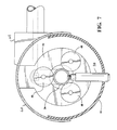
- FIG. 7 is a sectional view through the top member of FIG. 6 showing how the parts of the tubular housing slide relative to one another as the conduit and nozzles change direction.
- a spray arch for washing vehicles V is shown to comprise an arch-shaped, fixed frame 10 which, in this case, is permanently mounted to the floor 12 of the car wash facility and of such size as to permit vehicles V to be washed to pass through and under the fixed frame while being propelled along a path of vehicle travel by, for example, a conventional tunnel car wash conveyor.
- the fixed frame 10 is, for example, provided with wheels and mounted for longitudinal movement so as to permit it to be moved back and forth relative to a stationary vehicle.
- the term “fixed” as it refers to the frame 10 implies only that the frame is fixed in its overall configuration and does not necessarily convey the meaning that it is immovable relative to its environment.
- the fixed frame 10 comprises double parallel upright metal beams 14 , arranged in pairs on each side of the frame.
- These beams 14 may be made of many materials but are preferably hollow aluminum beams.
- the beams can have an oval, square or rectangular cross-section.
- Parallel cross beams 16 are fastened by bolted assembly brackets to complete the arch and provide a rigid structure capable of tolerating the weights and inertial forces created by the additional structure described hereinafter.
- the transit frame 18 comprises left and right side arms 20 which are more or less vertical and a top cross-arm 22 connected at its left and right ends to the tops of the side arms 20 by pivot structures including sets of plastic rollers 24 .
- the rollers 24 are actually cam followers as they are mounted within cam slots 25 formed in slide members 26 which are bolted, welded or otherwise fixed to the upper corners of the fixed frame 10 to define the direction and range of motion through which the structural elements of the transit frame move during a typical operation hereinafter described.
- a rocking motion of the transit frame 18 is produced by a crank system including a motor 28 mounted to the top beams 16 of the fixed frame 10 .
- the motor 28 could be mounted on any fixed support but the top beam of the frame 10 is convenient for this purpose.
- the motor 28 is connected to a two-part crank arrangement 30 which, in turn, is connected at 29 to the top arm 22 of the transit frame 18 so as to cause the top arm 22 of the transit frame, and anything carried by it, to rock back and forth as if it were suspended from an overhead pendulum arm having a fulcrum point approximately 12′ above the center of the top arm 22 of the transit frame 18 .
- the slides 26 accommodate the rocking motion and program or guide the transit frame during its cyclical motion relative to the fixed frame 10 .
- the lower ends of the transit frame arms 20 are provided with pivotal slide structures 44 which allow several inches of vertical movement as well as angular changes. Simple pivotal slides may also be used.
- the side arms 20 of the transit frame rise and fall through a range of about 4-8′′ and sway back and forth relative to the fixed frame 10 during a complete cycle of the rocking motion imparted to the upper arm 22 of the transit frame 18 as shown in FIGS. 1-3 .
- the left arm 20 is in a full upright position and leaning left while the right arm 20 is in a full downward position.
- the resulting geometric figure is left-leaning wherein the top of the geometric figure is non-horizontal.
- the arms 20 both point downwardly.
- the frame arm 22 is level.
- the resulting shape shown in FIG. 2 is that of a regular upright rectangle.
- the frame arm 22 is lower on the left side, the side arm 20 is fully down and leaning right while the right arm 20 is fully upright but also leaning to the right.
- the transit frame 18 carries a spray system consisting of left and right side fluid conduits 32 having generally inwardly aimed spray nozzles 34 and an overhead or top conduit 36 having generally downwardly directed nozzles 38 .
- the top conduit 36 is interconnected for both fluid flow and mechanical integrity with the side conduits 32 by means of flexible couplings 42 shown in FIG. 4 .
- These couplings are hollow rubber tubes so as to carry fluid, reinforced so as to be capable of transmitting torque from a twisting top conduit 36 to a twistable side conduit 32 as hereinafter described.
- All of the conduits 32 , 36 can be metal pipes, plastic pipes or relatively stiff reinforced rubber tubes, metal being preferred because metal facilitates the installation of threaded nozzles 34 using a drilling and tapping operation.
- the conduits 32 and 36 are mounted relative to the side and top beams of the transit frame by means of metal stand-offs 43 having bushings to permit the conduits to be twisted or changed in orientation so as to direct the spray patterns from the nozzles 34 in either of two directions, one being generally toward an approaching vehicle passing through the arch along the floor 12 and the other being generally aimed more toward a receding vehicle as it continues its progress through the arch.
- the transition from one spray nozzle orientation to the other occurs at a predetermined point, such as when the side-mounted rear view mirrors pass the side structures 14 of the arch 10 as sensed by an electric eye or sonic sensor 45 or a touch wand connected to a limit switch or a suitable control system smart enough to know the position and length of a vehicle.
- the orientation change can also occur when the rear tire of the vehicle reaches the side nozzles.
- the top conduit 36 is also mounted to the upper structural members 22 of the transit frame by means of stand-offs 43 also having bushings to permit twisting of the conduit 36 to reorient the nozzles 38 through an angular travel of about 60°; i.e., plus and minus 30° from neutral, so as to be first aimed toward an approaching vehicle and, as the vehicle is about half-way through the arch, switched 60° to an orientation which tends to follow a receding vehicle. In this way, fluids are directed toward the front of an approaching vehicle and toward the rear of a receding vehicle. The change in nozzle direction need not be exactly at the halfway point.
- a sensor 45 detects vehicle position to trigger the switch.
- the twisting motion of the conduits 36 , 32 is produced by an air cylinder actuator 40 which is mounted to the top structural arm 22 of the transit frame 18 and connected to the conduit 36 by way of a crank arm.
- the air cylinder 40 is connected to a suitable high-pressure air supply by flexible plastic conduits in a conventional fashion and triggered by a control system as generally described above.
- the twisting motion which is applied to the conduit 36 is transmitted through the couplings 42 to the side conduits 32 so that all of the conduits 36 , 32 move in unison while at the same time washing and/or rinsing fluids are conveyed through the conduits to the nozzles 34 , 38 to wash a vehicle in the desired fashion.
- the arch provides a timed change in side and top nozzle orientation in two ways: first, the aiming direction of the nozzles 34 relative to the vehicle V changes about 60° as the vehicle passes through the arch 10 ; second, the transit frame 18 sways and changes shape continuously in a parallelogram motion changing not only the orientations of the spray conduits but the distances between the nozzles and the vehicle as well.
- the aesthetics of the unit may be improved by constructing the transit frame to include partially translucent plastic housings 46 which enclose the spray conduits but have openings for the nozzles 34 and 38 .
- brackets 50 carry three spaced rollers 48 that grip the conduits 36 .
- the housings comprise an aluminum half-cylinder 60 mounted by brackets 62 to the transit frame. Slidingly mounted within the fixed half-cylinder 60 is a translucent half-cylinder 46 with longitudinally-spaced openings that allow nozzles 38 to extend therethrough. The circumferential sweep of half-cylinder 46 is about 220°.
- the sleeve-like half-cylinder 46 is carried along, slidingly rotating within the aluminum body provided by half-cylinder 60 .
- LED strips may be mounted within the housings to illuminate them along their lengths in an aesthetically pleasing way, suitable lighting systems being described in the co-pending applications, Ser. Nos. 13/025,466 and 12/707,777, incorporated herein by reference.
Abstract
Description
Claims (11)
Priority Applications (1)
| Application Number | Priority Date | Filing Date | Title |
|---|---|---|---|
| US13/847,513 US9162652B2 (en) | 2012-05-04 | 2013-03-20 | Car wash spray arch |
Applications Claiming Priority (2)
| Application Number | Priority Date | Filing Date | Title |
|---|---|---|---|
| US201261642840P | 2012-05-04 | 2012-05-04 | |
| US13/847,513 US9162652B2 (en) | 2012-05-04 | 2013-03-20 | Car wash spray arch |
Publications (2)
| Publication Number | Publication Date |
|---|---|
| US20130291909A1 US20130291909A1 (en) | 2013-11-07 |
| US9162652B2 true US9162652B2 (en) | 2015-10-20 |
Family
ID=49511612
Family Applications (1)
| Application Number | Title | Priority Date | Filing Date |
|---|---|---|---|
| US13/847,513 Active 2033-08-30 US9162652B2 (en) | 2012-05-04 | 2013-03-20 | Car wash spray arch |
Country Status (1)
| Country | Link |
|---|---|
| US (1) | US9162652B2 (en) |
Cited By (1)
| Publication number | Priority date | Publication date | Assignee | Title |
|---|---|---|---|---|
| US20210346907A1 (en) * | 2017-05-10 | 2021-11-11 | Howco, Inc. | Tire dressing machine and application method |
Families Citing this family (5)
| Publication number | Priority date | Publication date | Assignee | Title |
|---|---|---|---|---|
| CA2886427C (en) | 2014-03-28 | 2022-10-18 | Ryan D. Oliver | Touchless vehicle wash with conveyer system |
| JP2018524548A (en) * | 2015-07-31 | 2018-08-30 | マウリツィオ・ネグリ | Electric vehicle cooling system and manufacturing method thereof |
| CN107350212B (en) * | 2017-08-28 | 2023-03-14 | 中信戴卡股份有限公司 | Intelligence wheel hub belt cleaning device |
| US11590939B2 (en) * | 2020-08-24 | 2023-02-28 | Nti Co., Ltd | Brushless car wash system including a traveling module for washing side surfaces of vehicles |
| US11639157B2 (en) | 2020-08-24 | 2023-05-02 | Nti Co., Ltd | Brushless car wash system including a telescoping unit for washing top and rear surfaces of vehicles |
Citations (4)
| Publication number | Priority date | Publication date | Assignee | Title |
|---|---|---|---|---|
| US651828A (en) * | 1899-11-06 | 1900-06-19 | Alexander W Copland | Mechanical movement. |
| US3701356A (en) * | 1969-06-16 | 1972-10-31 | Daniel C Hanna | Car washing apparatus |
| US4788993A (en) * | 1986-06-23 | 1988-12-06 | Sherman Industries, Incorporated | Vehicle reciprocating spray washing apparatus |
| US20100154843A1 (en) * | 2008-12-23 | 2010-06-24 | Ennis G Thomas | Liquid applicator for cleaning a vehicle |
-
2013
- 2013-03-20 US US13/847,513 patent/US9162652B2/en active Active
Patent Citations (4)
| Publication number | Priority date | Publication date | Assignee | Title |
|---|---|---|---|---|
| US651828A (en) * | 1899-11-06 | 1900-06-19 | Alexander W Copland | Mechanical movement. |
| US3701356A (en) * | 1969-06-16 | 1972-10-31 | Daniel C Hanna | Car washing apparatus |
| US4788993A (en) * | 1986-06-23 | 1988-12-06 | Sherman Industries, Incorporated | Vehicle reciprocating spray washing apparatus |
| US20100154843A1 (en) * | 2008-12-23 | 2010-06-24 | Ennis G Thomas | Liquid applicator for cleaning a vehicle |
Cited By (1)
| Publication number | Priority date | Publication date | Assignee | Title |
|---|---|---|---|---|
| US20210346907A1 (en) * | 2017-05-10 | 2021-11-11 | Howco, Inc. | Tire dressing machine and application method |
Also Published As
| Publication number | Publication date |
|---|---|
| US20130291909A1 (en) | 2013-11-07 |
Similar Documents
| Publication | Publication Date | Title |
|---|---|---|
| US9162652B2 (en) | Car wash spray arch | |
| KR102453624B1 (en) | Photovoltaic panel cleaning robotic device | |
| US9060659B2 (en) | Cleaning vehicle and cantilever system of the cleaning vehicle | |
| US4788993A (en) | Vehicle reciprocating spray washing apparatus | |
| CN105438291A (en) | Robot moving platform with deformable tracks | |
| CN102974491A (en) | Conveying system of automobile side window | |
| US5725003A (en) | Vehicle washing apparatus | |
| CN108554891A (en) | A kind of control arm of washing and disinfection car | |
| CN206528542U (en) | A kind of deformable avoidance robot moving platform | |
| US6394370B1 (en) | Reciprocating wand vehicle wash apparatus | |
| CN204636198U (en) | Reciprocal telescopic formula glass-cleaning robot | |
| US7971594B2 (en) | Pendulum-type wheel washer | |
| CN207291956U (en) | A kind of gantry swing arm automatic car washing mechanism | |
| CN105109463B (en) | Jetting machine spray equipment and cleaning method | |
| KR200383476Y1 (en) | Apparatus to operate swing twist jet in fountain | |
| CN204107927U (en) | A kind of cleaning device | |
| CN202258167U (en) | Large roof light-emitting diode (LED) screen overturning mechanism | |
| CN108104863A (en) | Subway undermines intelligent dust falling system and method in construction | |
| CN106390484B (en) | Fountain egression performance appts in water | |
| CN205095425U (en) | Aquatic dolphin performance device | |
| KR200446141Y1 (en) | 2-shaft driving apparatus of nozzle for fountain | |
| CN203294761U (en) | Medical liquid bottle automatic arranging conveying machine capable of preventing bottle body from falling down | |
| CN103332474A (en) | Medical fluid bottle automatic shaping and arranging conveyor for preventing bottle body from toppling over | |
| CN103303665A (en) | Automatic conveyor for to-be-filled medical liquid bottles | |
| CN2644013Y (en) | Improved dynamic fountain device with peacock screen opening shape |
Legal Events
| Date | Code | Title | Description |
|---|---|---|---|
| AS | Assignment |
Owner name: BELANGER, INC., MICHIGAN Free format text: ASSIGNMENT OF ASSIGNORS INTEREST;ASSIGNORS:BELANGER, MICHAEL J.;TURNER, BARRY S.;TOGNETTI, DAVID L.;AND OTHERS;REEL/FRAME:036206/0356 Effective date: 20130319 |
|
| STCF | Information on status: patent grant |
Free format text: PATENTED CASE |
|
| AS | Assignment |
Owner name: WASHME PROPERTIES, LLC, MICHIGAN Free format text: ASSIGNMENT OF ASSIGNORS INTEREST;ASSIGNOR:BELANGER, INC.;REEL/FRAME:042038/0774 Effective date: 20170307 |
|
| AS | Assignment |
Owner name: PISTON OPW, INC., OHIO Free format text: ASSIGNMENT OF ASSIGNORS INTEREST;ASSIGNOR:BELANGER, INC.;REEL/FRAME:048322/0749 Effective date: 20190125 Owner name: BELANGER, INC., MICHIGAN Free format text: ASSIGNMENT OF ASSIGNORS INTEREST;ASSIGNOR:WASHME PROPERTIES, LLC;REEL/FRAME:049911/0643 Effective date: 20190125 |
|
| MAFP | Maintenance fee payment |
Free format text: PAYMENT OF MAINTENANCE FEE, 4TH YR, SMALL ENTITY (ORIGINAL EVENT CODE: M2551); ENTITY STATUS OF PATENT OWNER: SMALL ENTITY Year of fee payment: 4 |
|
| MAFP | Maintenance fee payment |
Free format text: PAYMENT OF MAINTENANCE FEE, 8TH YR, SMALL ENTITY (ORIGINAL EVENT CODE: M2552); ENTITY STATUS OF PATENT OWNER: SMALL ENTITY Year of fee payment: 8 |