US914101A - Truck-brake. - Google Patents
Truck-brake. Download PDFInfo
- Publication number
- US914101A US914101A US45297108A US1908452971A US914101A US 914101 A US914101 A US 914101A US 45297108 A US45297108 A US 45297108A US 1908452971 A US1908452971 A US 1908452971A US 914101 A US914101 A US 914101A
- Authority
- US
- United States
- Prior art keywords
- brake
- truck
- socket
- ball
- housing
- Prior art date
- Legal status (The legal status is an assumption and is not a legal conclusion. Google has not performed a legal analysis and makes no representation as to the accuracy of the status listed.)
- Expired - Lifetime
Links
- 238000005266 casting Methods 0.000 description 8
- 239000000428 dust Substances 0.000 description 1
- 210000005069 ears Anatomy 0.000 description 1
- 230000000266 injurious effect Effects 0.000 description 1
- XLYOFNOQVPJJNP-UHFFFAOYSA-N water Substances O XLYOFNOQVPJJNP-UHFFFAOYSA-N 0.000 description 1
Images


Classifications
-
- B—PERFORMING OPERATIONS; TRANSPORTING
- B61—RAILWAYS
- B61H—BRAKES OR OTHER RETARDING DEVICES SPECIALLY ADAPTED FOR RAIL VEHICLES; ARRANGEMENT OR DISPOSITION THEREOF IN RAIL VEHICLES
- B61H13/00—Actuating rail vehicle brakes
- B61H13/34—Details
Definitions
- ventio'n reference is to be had to the accomthe housing attached to a brake beams Figs.
- the object of my invention is to simplify and improve the structure of car brakes so that the brakes will obtain more satisfactory resultsthan those heretofore used. This object is accomplished by my invention, one I embodiment of Which is hereinafter set forth.
- Figure -1 is a side elevation of my improved brake, arts of truck being shown by dotted lines.
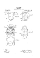
- ig. "2 is an end view of housing
- Fig. 3 is a side elevation of the same.
- Fig. 4 shows a housing in section and the hanger.
- Fig. 5 is a plan View ofthe structure shown in Figs. 2 and 3.
- Fig. 6 is a side elevation of 7 and 8 are end lan views of this housing, the brake beam eing omitted.
- Figs 9, 10, 11, 12, 13 and 14, are detail views showing portions of a socket.
- ig. 16 is a-side elevation of a ball with trunnions ada ted to fitin' the socket above igs. 17 and 18'are side and end elevations, respectively,'0f a portion of, a hanger.
- My improved right lever 2 which is connected to a bra e chain or similar device by 3 and the upper end of the upright lever 2 moves in a guide 4 secured to the truck 5 in any suitable. manner.
- The'lever .2 is fulcrumed at 6 in a crotch 7 secured to the brake beam 8 in any suitable manner, and the lower end of the upright lever 2 is pivoted at 9 to a sleeve 10 which is on a bolt 11 with screw threads of opposite pitch at its otherend and on which is mounted a corresponding sleeve 12 which is pivotally connected to a second upright lever 13 which passes through a crotch v14 which is secured to a brake beam 15 by any suitable means and the upper end of the upright lever .13 has an elongated opening 16 held together by rivets brake 1 consists of an'u castings 38 and 39 through which passes a pivot 17 which may of several holes 18 in v a bracket 19 carried by the truck 5.
- the sleeves 10 and 12 may be considered with the bolt 11 as a turn buckle, as by turning this bolt the sleeves 10 and 12 may be either drawn together or separated, as may be necessary for adjustment.
- the brake beams 8 and 15 also carry suitable brake shoe holders 20 which carry brake shoes 21 in the con-. ventional manner.
- the brake beams 8 and 15 are supported by suitable hangers 22 mounted near each endof Housings 23 are secured to the truck 5 and preferably to the transoms 24 or other suitable means.
- the housings 23 eachconsisting of two castings 25 and 26 are or other suitable means 27 and they are also provided with suitable ears 28 to which bolts 24 are secured. Between the castin s 25 and 26 are the elongated openings 29 t rough which extend the trunnions 30 of the ball 31.
- the hangers 22 are riveted or otherwise secured to trunnions 30 as shown in Fig. 4.
- the housings 23 also carry sockets 32 which sockets are composed of the wedges 33 and top casting 34, and the bottom castings 35. These socket castings are put on to the ball 31 and then the parts of the housings 23- are placed over these castings and then the parts 25 and 26 of the housings are rivetedtogether by the rivets 27 leaving the trunnions 30 of the ball 31 projecting through the openings 29.
- These openings 29 are covered by washer 36, so that be placed in any dust, Water or other injurious matter cannot enter the ball and 'bearin socket joint and a large surface will always be available for said-joint so that wear is reduced to a minimum.
- the wear is taken up automatically by the wed es 33 which have coiled springs 4.3 which also press against the housings.
- the Wedge 33 has a groove 44 and ,the socket 34'has a tongue 45 so that these parts will be held in proper relation.
- the ball and socket joint for the upper end of the hanger The lower end of the hanger supports the brake beam with the same identical ball 31 and trunnions 30 and sockets 32, but the housing 32 is different.
- the lower housings 37 are divided into two and 41 respectively, through which bolts pass to secure them to the brake beam8 or the thereof by bolts with projecting cars 40 brake beam 15.
- the castings 38 and 39 have elongated openings 42 between them through which trunnions 30 are adapted to pass.
- the hangers 22 do not hang vertically, but are splayed towards wheels at their lower ends so that when the brakes are released the wei ht of the shoes, shoe-holders and beams wil be suflicient to make the brake shoes leave the wheels without the action of any spring if such an action should be desired.
- hanger composed of a pair of links connected ing said socket, said housing being adapted to be secured to a truck and means supporting said housing and links for'preventing dirt from entering between said ball and socket.
- a pair of links connected at each endby a ball and trunnions, a socket on one of said balls and a housing surrounding said socket adapted to be secured to a truck and another socket on the other said ball and a housing surrounding this socket with means for securing the same to a brake beam.
- a housing composed of two castings having an opening between 'them and a three part socket, two parts of said socket being adapted to press against a ball and a third part being provided with springs and adapted to force one of said parts against said'ball.
Landscapes
- Engineering & Computer Science (AREA)
- Mechanical Engineering (AREA)
- Braking Arrangements (AREA)
Description
W. S. ADAMS.
TRUCK BRAKE.
APPLICATION FILED SBPT.14, 190s.
. Patented Mar. 2, 1909.
3 SHEETS-SHEET 1.
| l b 1 l I l W. S. ADAMS.
TRUCK BRAKE.
APPLIOATION FILED SEPT.14, 1908.
914;, 101 V Patented Mar. 2, 1909.
3 SHEETSSHEET 2.
q vi/bwwbao W. S. ADAMS.
TRUCK BRAKE. APPLICATION FILED SEPT 14, 1908.
Patented M21122, 1909.
3 SHEETS-SHEET 3.
" To all whom it may concern:
' referred to.
- which the ollow ingis a specification.
ventio'n reference is to be had to the accomthe housing attached to a brake beams Figs.
WALTER S. ADAMS, OF PHILADELPHIA,
PENNSYLVANIA, ASSIGNOR'TO THE J. G. BRILL COMPANY, OF PHILADELPHIA, PENNSYLVANIA,
TRUCK-BRAKE I Specification of Letters Patent.
Patented March 2, 1 909.
Application filed September 14,1908. Serial No. 452,971.
Be it known that I, WALTER S. ADAMS, citizen of the United States, and a resident of the city and county of Philadelphia, State 3 of Pennsylvania, have invented a new and useful Im rovement in Truck-Brakes, of
The object of my invention is to simplify and improve the structure of car brakes so that the brakes will obtain more satisfactory resultsthan those heretofore used. This object is accomplished by my invention, one I embodiment of Which is hereinafter set forth.
For a more particular description of my inpanying drawings forming a part hereof, in which: 1
Figure -1 is a side elevation of my improved brake, arts of truck being shown by dotted lines. ig. "2 is an end view of housing, Fig. 3 is a side elevation of the same. Fig. 4 shows a housing in section and the hanger. Fig. 5 is a plan View ofthe structure shown in Figs. 2 and 3. Fig. 6 is a side elevation of 7 and 8 are end lan views of this housing, the brake beam eing omitted. Figs 9, 10, 11, 12, 13 and 14, are detail views showing portions of a socket. Fig. 15sh0ws awasher.
ig. 16 is a-side elevation of a ball with trunnions ada ted to fitin' the socket above igs. 17 and 18'are side and end elevations, respectively,'0f a portion of, a hanger.
Throughout the various views of the drawings, similar referencecharacters designate s1m1lar parts.
My improved right lever 2 which is connected to a bra e chain or similar device by 3 and the upper end of the upright lever 2 moves in a guide 4 secured to the truck 5 in any suitable. manner. The'lever .2 is fulcrumed at 6 in a crotch 7 secured to the brake beam 8 in any suitable manner, and the lower end of the upright lever 2 is pivoted at 9 to a sleeve 10 which is on a bolt 11 with screw threads of opposite pitch at its otherend and on which is mounted a corresponding sleeve 12 which is pivotally connected to a second upright lever 13 which passes through a crotch v14 which is secured to a brake beam 15 by any suitable means and the upper end of the upright lever .13 has an elongated opening 16 held together by rivets brake 1 consists of an'u castings 38 and 39 through which passes a pivot 17 which may of several holes 18 in v a bracket 19 carried by the truck 5. The sleeves 10 and 12 may be considered with the bolt 11 as a turn buckle, as by turning this bolt the sleeves 10 and 12 may be either drawn together or separated, as may be necessary for adjustment. The brake beams 8 and 15 also carry suitable brake shoe holders 20 which carry brake shoes 21 in the con-. ventional manner. The brake beams 8 and 15 are supported by suitable hangers 22 mounted near each endof Housings 23 are secured to the truck 5 and preferably to the transoms 24 or other suitable means. The housings 23 eachconsisting of two castings 25 and 26 are or other suitable means 27 and they are also provided with suitable ears 28 to which bolts 24 are secured. Between the castin s 25 and 26 are the elongated openings 29 t rough which extend the trunnions 30 of the ball 31. The hangers 22 are riveted or otherwise secured to trunnions 30 as shown in Fig. 4. The housings 23 also carry sockets 32 which sockets are composed of the wedges 33 and top casting 34, and the bottom castings 35. These socket castings are put on to the ball 31 and then the parts of the housings 23- are placed over these castings and then the parts 25 and 26 of the housings are rivetedtogether by the rivets 27 leaving the trunnions 30 of the ball 31 projecting through the openings 29. These openings 29 are covered by washer 36, so that be placed in any dust, Water or other injurious matter cannot enter the ball and 'bearin socket joint and a large surface will always be available for said-joint so that wear is reduced to a minimum. The wear is taken up automatically by the wed es 33 which have coiled springs 4.3 which also press against the housings. The Wedge 33 has a groove 44 and ,the socket 34'has a tongue 45 so that these parts will be held in proper relation. -In the preceding paragraph has been described the ball and socket joint for the upper end of the hanger. The lower end of the hanger supports the brake beam with the same identical ball 31 and trunnions 30 and sockets 32, but the housing 32 is different.
The lower housings 37 are divided into two and 41 respectively, through which bolts pass to secure them to the brake beam8 or the thereof by bolts with projecting cars 40 brake beam 15. The castings 38 and 39 have elongated openings 42 between them through which trunnions 30 are adapted to pass.
As shown in Fig. 1 the hangers 22 do not hang vertically, but are splayed towards wheels at their lower ends so that when the brakes are released the wei ht of the shoes, shoe-holders and beams wil be suflicient to make the brake shoes leave the wheels without the action of any spring if such an action should be desired.
As my improved brake is used in the conventional manner, it is not necessary to describe its action in detail. It is suflicient to say that the ball and socket connections of the hangers to the housings permit the brake beams to have a limited universal movement 'so that they will always adjust themselves to any small inequalities andonable the brake shoes to rub firm and true against the wheels.- The structure is also such that the ball and socket oints will be kept absolutely free from dirt or other matter that would tend to corrode or injure them.
While I have shown and described one embodiment of my invention, it is obvious that it is not restricted thereto, but that it is broad enough to cover all structures that come within the scope of the annexed claims.
Having thus described my invention, what I claim is:
1. In a device of the class described, a
hanger composed of a pair of links connected ing said socket, said housing being adapted to be secured to a truck and means supporting said housing and links for'preventing dirt from entering between said ball and socket.
3. In a device of the class described, a pair of links connected at each endby a ball and trunnions, a socket on one of said balls and a housing surrounding said socket adapted to be secured to a truck and another socket on the other said ball and a housing surrounding this socket with means for securing the same to a brake beam.
4. In a device of the class described, a housing composed of two castings having an opening between 'them and a three part socket, two parts of said socket being adapted to press against a ball and a third part being provided with springs and adapted to force one of said parts against said'ball.
Signed at Philadelphia, Pa. the 9th day of September, 1908.
WALTER S. ADAMS.
Witnesses:
HARRY F.:MoK1LL1P, HENRY O. ESLING.
Priority Applications (1)
| Application Number | Priority Date | Filing Date | Title |
|---|---|---|---|
| US45297108A US914101A (en) | 1908-09-14 | 1908-09-14 | Truck-brake. |
Applications Claiming Priority (1)
| Application Number | Priority Date | Filing Date | Title |
|---|---|---|---|
| US45297108A US914101A (en) | 1908-09-14 | 1908-09-14 | Truck-brake. |
Publications (1)
| Publication Number | Publication Date |
|---|---|
| US914101A true US914101A (en) | 1909-03-02 |
Family
ID=2982537
Family Applications (1)
| Application Number | Title | Priority Date | Filing Date |
|---|---|---|---|
| US45297108A Expired - Lifetime US914101A (en) | 1908-09-14 | 1908-09-14 | Truck-brake. |
Country Status (1)
| Country | Link |
|---|---|
| US (1) | US914101A (en) |
-
1908
- 1908-09-14 US US45297108A patent/US914101A/en not_active Expired - Lifetime
Similar Documents
| Publication | Publication Date | Title |
|---|---|---|
| US1191136A (en) | Wheeled support for railroad-vehicles. | |
| US914101A (en) | Truck-brake. | |
| US491664A (en) | roberts | |
| US1426506A (en) | Brake-beam hanger | |
| US424677A (en) | Brake for vehicles | |
| US378477A (en) | Officeo | |
| US1421697A (en) | Brake release spring mechanism for tram and the like cars | |
| US2821147A (en) | Railway truck bolster mounting | |
| US1150741A (en) | Swing-link bearing for trucks. | |
| US1163046A (en) | Brake-rigging safety appliance. | |
| US1733705A (en) | Articulated car | |
| US764670A (en) | Brake for railway-cars. | |
| US1888176A (en) | Railway truck | |
| US849193A (en) | Swing-motion truck. | |
| US708477A (en) | Emergency-brake. | |
| US725344A (en) | Truck. | |
| US963459A (en) | Roller side bearing. | |
| US1377704A (en) | A cobpobation of new jebsey | |
| US1535230A (en) | Car truck | |
| US561873A (en) | dudley | |
| US926920A (en) | Brake. | |
| US788082A (en) | Side bearing for railway rolling-stock. | |
| US452919A (en) | Car-truck | |
| US919671A (en) | Brake. | |
| US539977A (en) | Car-truck |