US910941A - Machine for slotting nuts. - Google Patents
Machine for slotting nuts. Download PDFInfo
- Publication number
- US910941A US910941A US39716007A US1907397160A US910941A US 910941 A US910941 A US 910941A US 39716007 A US39716007 A US 39716007A US 1907397160 A US1907397160 A US 1907397160A US 910941 A US910941 A US 910941A
- Authority
- US
- United States
- Prior art keywords
- nut
- nuts
- machine
- slotting
- punch
- Prior art date
- Legal status (The legal status is an assumption and is not a legal conclusion. Google has not performed a legal analysis and makes no representation as to the accuracy of the status listed.)
- Expired - Lifetime
Links
- 239000011435 rock Substances 0.000 description 8
- 238000004080 punching Methods 0.000 description 4
- 238000010276 construction Methods 0.000 description 2
- 238000005520 cutting process Methods 0.000 description 2
- 239000000463 material Substances 0.000 description 2
- 239000002184 metal Substances 0.000 description 2
- 102000004726 Connectin Human genes 0.000 description 1
- 108010002947 Connectin Proteins 0.000 description 1
- 101100340610 Mus musculus Igdcc3 gene Proteins 0.000 description 1
- 235000014787 Vitis vinifera Nutrition 0.000 description 1
- 240000006365 Vitis vinifera Species 0.000 description 1
- 238000004519 manufacturing process Methods 0.000 description 1
- 239000007769 metal material Substances 0.000 description 1
- 230000000630 rising effect Effects 0.000 description 1
- 239000002699 waste material Substances 0.000 description 1
Images


Classifications
-
- B—PERFORMING OPERATIONS; TRANSPORTING
- B21—MECHANICAL METAL-WORKING WITHOUT ESSENTIALLY REMOVING MATERIAL; PUNCHING METAL
- B21D—WORKING OR PROCESSING OF SHEET METAL OR METAL TUBES, RODS OR PROFILES WITHOUT ESSENTIALLY REMOVING MATERIAL; PUNCHING METAL
- B21D28/00—Shaping by press-cutting; Perforating
- B21D28/02—Punching blanks or articles with or without obtaining scrap; Notching
- B21D28/12—Punching using rotatable carriers
-
- B—PERFORMING OPERATIONS; TRANSPORTING
- B23—MACHINE TOOLS; METAL-WORKING NOT OTHERWISE PROVIDED FOR
- B23Q—DETAILS, COMPONENTS, OR ACCESSORIES FOR MACHINE TOOLS, e.g. ARRANGEMENTS FOR COPYING OR CONTROLLING; MACHINE TOOLS IN GENERAL CHARACTERISED BY THE CONSTRUCTION OF PARTICULAR DETAILS OR COMPONENTS; COMBINATIONS OR ASSOCIATIONS OF METAL-WORKING MACHINES, NOT DIRECTED TO A PARTICULAR RESULT
- B23Q7/00—Arrangements for handling work specially combined with or arranged in, or specially adapted for use in connection with, machine tools, e.g. for conveying, loading, positioning, discharging, sorting
- B23Q7/02—Arrangements for handling work specially combined with or arranged in, or specially adapted for use in connection with, machine tools, e.g. for conveying, loading, positioning, discharging, sorting by means of drums or rotating tables or discs
-
- Y—GENERAL TAGGING OF NEW TECHNOLOGICAL DEVELOPMENTS; GENERAL TAGGING OF CROSS-SECTIONAL TECHNOLOGIES SPANNING OVER SEVERAL SECTIONS OF THE IPC; TECHNICAL SUBJECTS COVERED BY FORMER USPC CROSS-REFERENCE ART COLLECTIONS [XRACs] AND DIGESTS
- Y10—TECHNICAL SUBJECTS COVERED BY FORMER USPC
- Y10T—TECHNICAL SUBJECTS COVERED BY FORMER US CLASSIFICATION
- Y10T29/00—Metal working
- Y10T29/51—Plural diverse manufacturing apparatus including means for metal shaping or assembling
- Y10T29/519—Turret
Definitions
- Witne sses Wagner 0 7 v By ttbrney A. L. MOWRY.
- FIG. 2B is a diagrammatic representation of FIG. 2B.
- This invention relates to improvements in machines i or slotting nuts particularly ad apt able for the manufacture of lock nuts in which a lockin pin operates in a slot pro vided in the sic e of the nut, and the objects of mv invention are to provide a machine in which the opreation 0i slotting may be carried out continuously and automatically, whereby the nuts may be produced with great rapidity at an exceedingly low cost.
- a further object of the invention is to provide means for lessening thewwear on the unches used in the slottin operation where.- v their life may' be extent ed and the cost of roduotion reduced.
- a further object still is to rovide means for checking the operation 0? the machine whereby, it the punches should fail to register with the nuts to be punched, the operation of the machine may be automaticall sus ended.
- nembodiment of my invention for attaining these objects consists essentially of a reciprocating punch block having a plurality of punches therein, and teeth on each punchbeing adapted to take a cut'of successivel3 increased depth, dies cooperating with the unches', a nut car rying ring having a plum ity of not carrying pockets, at bolster plate supporting the not carrying rin and having a slot therein through whic the completed nuts are adapt ed to drop, reversed ratchet wheels formed on the-ring, pawls cooperating therewith, means for actuating the intermittent movement to the ring, a lever having an end adapted to ride on the ring and extend successively in the pockets therein, means operated by the raising of the said lever for throwin the punch'out of operation, a grinding w ieel, and means for bringing the same in contact with each nut to re move the scale from the surface of the nut where the slotis to be cut.
- .19 isa plan view of the bearing I shows a detail of the the connecting pawls to impart an.
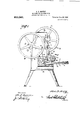
- Figure 1 shows. a front elevation of the machine.
- Fig. 2 'showsa side elevation.
- Fig. B shows an enlarged de tail of the top of the punch block.
- Fig. 4 shows an enlar ed detail of the side of the punch block; *ig, 5 is an enlarged detail, partially in section, illustratin the piston valve controlling the flow of in ricating oil.
- Fig. 6 is a plan view of the disk on-t'he crank shaft used for operating one of the pawls.
- Fig. 7 is a detail of a pin i .the side of said disk.
- Fig. 8 shows a detail of the bell and plate adapted to form thelconnecting means etween the disk and the operating bell .crank.
- Fig. 9 is a plan view of t 1e die holder.
- Fig. 10' shows a side view of the same.
- Fig. 11 shows a top view of one of the dies.
- Fig. 12 shows a sectional view through the same Fig. 13 shows versed position.
- Fig. 14 is a pawl-operating mechanism.
- Fig. .15 is a plan view of the same.
- Fig. 16 is a detail of one of the awls.
- Fig. 17 is a detail of a tappet use to intermittently oplerate the pawl.
- Fig. 9 is a plan view of t 1e die holder.
- Fig. 10' shows a side view of the same.
- Fig. 11 shows a top view of one of the dies.
- FIG. 18 is a top view of e bolster plate supporting the nut carrying .letail of the ring.
- Fig. transverse sectional viewthrough the 20 is a side view.
- Fig. 21 is a plates inserted on the inner side of the neck ring.
- Fig. 22 shows in detail the means for reventing the operation of the machine s'hou d the punches failto register with the nuts.
- Fig. 23 shows an elevation of the nut stripper.
- Fig. 24 shows a plan view of the same.
- Fig. 25 bearing bracket 'for the Fig. 26 shows a detail of lever between the grinding which the same is same.
- Fig. 27 shows a front view of the punch.
- Fig. 28 shows a side view of the same.
- Fig. 29 is a sectiona detail view showing stripper plate in assembled relation with other parts.
- A is the rl'lain frame of th punch which can be of any suitahlr ons1 Motion and which supports the u per bravura B in which are bearings a and for the crank shaft C.
- This a side view of the die in its 1* 1 crank shaft, as usual, has a car c thereon which meshes with a pinion on the main shaft D on which the driving ulle e is secured.
- E is a ram )erater iy tie crank shaft on the lower our of which is a punch block F sup orting a plurality of punches f.
- a die holder shown in detail in Figs. 9vand 10 and which is supported in position beneath the unches by means of a bolster plate H whic 1s bolted or otherwise secured to the main frame.
- the connection between the die holder and the bolster plate is pref erably of aremovable character andin the so embodiment illustrated is formed by a dovetailed recess 1' inthe bolster plate, into which the die holder extends.
- the die holder are a pluralityof a ertures k within which the dies are secure ,beindgl held therein by means of set screws exten 'ng through holes 5.
- the bolster p'late H has also a plurality of apertures m therein beneath theapertures k of slightly smaller diameter whereby they will support the die itself but permit the punch to go throughand clear itself of the material cut.
- a nut stri per I shown in detail in Figs. 23 and 24 and which, revents the nut rising with the punches.
- his nut stripperextends quite close to the nut ring and in the embodiment illustrated comprises a plate n having a pluralit of apertures o therein through which t e punches extend and also havin so integral therewith standards 12 and g wluc are secured to the upper frame B.
- the nuts are presented to the operation of the unches b means of a nut-carrying ring J (shown in dhtail in Fig. '15) which is retatably supported on bolster plates H which is, for that p urpose, of the circular shape shown. 'Ihe lateral movement. of thering is prevented b the bearing ring K wluch is secure by b0 ts s to lugs r on the bolster plate.
- the nut ring is intermittent] rotated to bring each of the nuts successlvely into position beneath the punches by a suitable mechanism, that I ave shown consisting of two reverse ratchet wheels K and L formed integral with the nut carrying ring and on which operate the feeding-pawl v and the stop-pawl w.
- a suitable mechanism that I ave shown consisting of two reverse ratchet wheels K and L formed integral with the nut carrying ring and on which operate the feeding-pawl v and the stop-pawl w.
- These pawls may be operated by any' suitable mechanism, the essential feature being that the stop-pawl locks the ring while the punchin o eration is being carried out.
- both pawls are operated from a rock shaft M sup orted from the 'frame by bearings a: and 'y aving at one end thereof a crank 2 connected to the crank shaft b the means illustrated in Figs. 6, 7, 8 an 14.
- These means comprise a disk 3 secured to the crank shaft and having thereon a pin 4 which extends through a slot 5 and a bell crank lever 6 which is pivoted on the shaft 7 supgorted in a bearing 8 secured to the bracket
- the opposite arm ofthe bell crank of the lever 6 is provided with a slot 9 in which operates a pin 10'secured to a connectin link 11' the opposite end of which has a in 12 which extends through the slot 13 m'the crank 21.
- the hell'crank is oscillated which oscillates the crank z through the connecting link 11.
- the connecting link 11 is made of light metallic material whereby it will possess a certain amount of flexibility for a purpose hereinafter described.
- the feed- .pawl 'v is directly operated lby the crank 14 secured'on the rock shaft M and pivoted to the pawl.
- the stopwl w is normall held a in engaged position y a tension spring 15 the opposite end of which is connected to the.
- the crank disk 3 has a pluralit of holes 50 in the periphery thereof, into w ich bars may be insertedto-rotate the crank shaft by hand.
- I provide the mechanism illus 120 trated in detail in Fig. 22, and which consists of a lever N pivoted at 1% to the trams and having the opposite end 19 downwardly and horizontally curved'and ada ted to extend ceived after the same have been emptied.
- This lever has connected to it, intermediate of its length, a link bar 20 the opposite end of which is connected to the lever 21 intermediate of its length, one end of said lever being pivoted at 22 to the frame and the opposite end 23 being adapted in its uppermost position to engage the clutch pin 24, which when rotated, throws the clutch out of operation.
- the mechanism for doing is well-known in the art and ap lied to practically all forms of similar punc es and so need not be described herein in detail.
- the end of the lever N is adapted to. alternately extend into and ride over the pockets and when the 'ring is in position for punching, the end of the lever will be extending into the pockets.
- the lever N will be in its raised position, raising the lever 21 in such a position that it will operate the clutch pin.
- I provide a hand lever O pivoted at 25 to the frame and having intermediate ofits lengthen operating rod 26 pivoted thereto which extends through the bearing 27 secured to the frame and has the opposite end thereof abutting the underside of the lever 21.
- This consists essentially of a grinding wheel 28 of suitable material supported on the shaft 29 journaled in a bearing 31 which is vertically slidable in a slot 32 in the bracket 36 secured to the frame, being held therein by a pin 37 having an enlarged end.
- the grinding Wheel is raised and lowered in vertical position by means of an arm 37, having a slot 39 therein into which the pin on the bearing 31 extends, the upper end of the arm 37 being turned horizontally and secured to an abutment 40 secured to the reciprocating punch block 7.
- the grinding wheel comes in contact with the nut inthe feed ring J and remains there until the ram travels two-thirds of the upper stroke thus allowing the wheel to remove the scale from the exact spot on the nut where the slot is to be cut. itself is rotated in any suitable manner, preferably as shown, from a pulley 41 secured to the end of the shaft to which the driving belt will be secured.
- the form of punch used in my machine is shown in Figs. 27 and 28 and consists of a cylindrical body 42 having an outwardlv protruding tooth 43 on one side thereof whic may be formed integral therewith but is preferably separable and secured in a dove tailed recess in the side of the body portion, where- 'b when Worn out it may be removed. and relaced without destroying the bodv portion.
- the punch has a central hole 44 for the in- Moduction of oil and the tooth has a portion cut away to form. a recess'45 with which the said oil" assageways communicate.
- the die used inrny machine is shown The grinding wheel detail in Fi 's.
- the recess 48 communicates with a laterally extending recess 49 through which the oil flows and carries-the waste cuttings.
- each nut will be first moved into position beneath the iirst punch and operated on thereby. This first punch is arranged to take. a cut which will remove the metal fromthe nut down to the depth of the, thread. It will then be connected to the remaining four punches which will take cuts of successively increased depth until the final punch cuts the exact shape of hole desired in the nut. As soon as the nut comes opposite the a erture u in the bolster plate it Wlll drop theret rough into a suitable receptacle.
- a nut slotting machine the combination with the main frame and main shaft therein, a nut carrier, two ratchet Wheels formed thereon, pawls engaging the ratchet wheels, a rock shaft, connecting means between the rock shaft and the pawls whereby onepawl actuates one ratchet Wheel and the other pawl operates as a stop with the opposite ratchet wheel, a crank on the main shaft, a crank on the rock shaft, an intermediate crank, and connecting means between the intermediate crank and the cranks on the rock shaft and the main shaft.
- the combination ith the reciprocatable punch block and the nut carrier, of a grinding wheel, a shaft secured thereto, a bearing for the shaft, a bracket having a slot therein, a pin secured to the bearing and extendin through a slot in the bracket, a pin on the hearing, an arm having a slot therein through which the pin extends and having the opposite end thereof connected to the punch block.
- nut carrier is registered with the punches and means operated b r the raising of the lever for throwing the riving mechanism out of '6.
- a punch driving mechanism a clutch for throwing the same in and out of gear
- a clutch. pin controlling the same, a nut carrier having pockets therein adapted to register with the punches, means for intermittently rotating the nut carrier a pivoted arm having one end adapted to extend into the pockets, means qperated by the raising of the arm out of the pockets for actuating the clutch pin to throw the clutch out of gear.
- a clutch pin controllin the same, a nut carrier having a plurality 0 pockets therein adapted to register with the punches, and means for intermittently rotating the nut carrier, of a pivoted arm having one end adapted to extend into the pocketsjineans operated by the raisin of the arm out of the pockets for actuating t e clutch pin to throw the clutch out of gear, and a separate pivoted hand-lever for actuating the clutch pin.
Landscapes
- Engineering & Computer Science (AREA)
- Mechanical Engineering (AREA)
- Press Drives And Press Lines (AREA)
Description
A..L. MOWRY.
MACHINE FOB SLOTTING NUTS. .u rnloulon FILED 00112. 1001.
910,941; Patentd Jan. 26, 1909:;
B BHEBT5-BHEET 1.
A. L. MOWRY. MACHINE FOR SLOTTING NUTS.
APPLICATION FILED 001212. 1907.
Patented Jan.26,1909.
8 SHEETS-SHEET 2 HIKE;
Wflnesses:
At orney A. L. MQWRY. MACHINE FOR SLOTTING NUTS.
APPLICATION FILED 001212, 1907.
Patented Jan. 26, 1909.
8 SHEETS-SHEET 3.
wltnesses:
Attorney A. L. MOWRY. MACHINE FOR SLOTTING NUTS. APPLICATION FILED OUT. 12. 1907.
910,941. Patented Jan. 26, 1909;
a SHEETS-SHEET 4.
Witnesses: In ntor,
{gig By Mam Attorney A. L. MOWRY. MACHINE FOR SLOTTING NUTS. APPLICATION FILED 001212, 1907.
910,941. Patented m. 26, 1909.
8 SHEETS-SHEET 5.
M f I Attorney A. L. MOWRY.
MACHINE FOR SLOTTING' NUTS. APPLIUATION FILED 001212. 1907.
910,941. Patented Jan. 26,1909.
8 SHEETS-SHEET B.
GWQIJW lnve tor,
VM/W
Attorney Witnesses.
A. L. MOWRY.
MACHINE FOB SLOTTING NUTS.
rum-r1021 mum 0012.12. 1901.
91 0,941 Patented Jan 26,1909.
Witne sses: Wagner 0 7 v By ttbrney A. L. MOWRY.
MACHINE FOR SLOT'IING NUTS. APPLICATION FILED 00112, 1907.
910,941 Patented Jan. 26, 1909.
3 SHEETS-SHEET 8.
FIG. 2B.
RE! E9 INVE'NTQR. WIT SS .A.L.MOWRYI "UNITED STATES PATENT OFFICE.
ALBERT LAWRENCE MOWRY, OF ST. JOHN, NEW BRUNSWICK, CANADA, ASSIGNOR TO HARRY RICHARDS MGLELLAN, OF ST. JOHN, CANADA.
MACHINE FOB SLOTTING NUTS.
To all whom it may concern:
Be it known that I, ALBERT LAWRENCE MownY, of the cit of St. John, in the county of St. John, Province of New Brunswick, Canada, have invented certain new and useful Improvements in Machines for Blotting "Nuts, of which the following is a specification. This invention relates to improvements in machines i or slotting nuts particularly ad apt able for the manufacture of lock nuts in which a lockin pin operates in a slot pro vided in the sic e of the nut, and the objects of mv invention are to provide a machine in which the opreation 0i slotting may be carried out continuously and automatically, whereby the nuts may be produced with great rapidity at an exceedingly low cost.
A further object of the invention is to provide means for lessening thewwear on the unches used in the slottin operation where.- v their life may' be extent ed and the cost of roduotion reduced.
A further object still is to rovide means for checking the operation 0? the machine whereby, it the punches should fail to register with the nuts to be punched, the operation of the machine may be automaticall sus ended.
nembodiment of my invention for attaining these objects is illustrated herein and consists essentially of a reciprocating punch block having a plurality of punches therein, and teeth on each punchbeing adapted to take a cut'of successivel3 increased depth, dies cooperating with the unches', a nut car rying ring having a plum ity of not carrying pockets, at bolster plate supporting the not carrying rin and having a slot therein through whic the completed nuts are adapt ed to drop, reversed ratchet wheels formed on the-ring, pawls cooperating therewith, means for actuating the intermittent movement to the ring, a lever having an end adapted to ride on the ring and extend successively in the pockets therein, means operated by the raising of the said lever for throwin the punch'out of operation, a grinding w ieel, and means for bringing the same in contact with each nut to re move the scale from the surface of the nut where the slotis to be cut. p
The detail of this construction together with others necessary to the attainment of Specification of Letters Patent. Application filed October 12, 1907.
.19 isa plan view of the bearing I shows a detail of the the connecting pawls to impart an.
Patented Ian. 26, 1909.
Serial N02 897,160.
the invention are hereinafter set forth in the accom anying specifications and drawings.
In t e drawings, Figure 1 shows. a front elevation of the machine. Fig. 2 'showsa side elevation. Fig. Bshows an enlarged de tail of the top of the punch block. Fig. 4 shows an enlar ed detail of the side of the punch block; *ig, 5 is an enlarged detail, partially in section, illustratin the piston valve controlling the flow of in ricating oil. Fig. 6 is a plan view of the disk on-t'he crank shaft used for operating one of the pawls. Fig. 7 is a detail of a pin i .the side of said disk. Fig. 8 shows a detail of the bell and plate adapted to form thelconnecting means etween the disk and the operating bell .crank. Fig. 9 is a plan view of t 1e die holder. Fig. 10'shows a side view of the same. Fig. 11 shows a top view of one of the dies. Fig. 12 shows a sectional view through the same Fig. 13 shows versed position. Fig. 14 is a pawl-operating mechanism. Fig. .15 is a plan view of the same. Fig. 16 is a detail of one of the awls. Fig. 17 is a detail of a tappet use to intermittently oplerate the pawl. Fig. 18 is a top view of e bolster plate supporting the nut carrying .letail of the ring. Fig. transverse sectional viewthrough the 20 is a side view. Fig. 21 is a plates inserted on the inner side of the neck ring. Fig. 22 shows in detail the means for reventing the operation of the machine s'hou d the punches failto register with the nuts. Fig. 23 shows an elevation of the nut stripper. Fig. 24 shows a plan view of the same. Fig. 25 bearing bracket 'for the Fig. 26 shows a detail of lever between the grinding which the same is same. Fig.
grinding wheel.
wheel and the punch by raised and lowered. Fig. 27 shows a front view of the punch. Fig. 28 shows a side view of the same. Fig. 29 is a sectiona detail view showing stripper plate in assembled relation with other parts.
In the drawings like letters and figures of reference indicate corresponding parts in each figure.
Referring in particular to Figs. 1 and 2, A is the rl'lain frame of th punch which can be of any suitahlr ons1 Motion and which supports the u per bravura B in which are bearings a and for the crank shaft C. This a side view of the die in its 1* 1 crank shaft, as usual, has a car c thereon which meshes with a pinion on the main shaft D on which the driving ulle e is secured. E is a ram )erater iy tie crank shaft on the lower our of which is a punch block F sup orting a plurality of punches f.
The detais of my machine thus far described are common to any of theordinar typti of punches and may be varied if desil'e( lo'lhe det ailsof the punch block itself re shown in Figs. 3, 4, and 5 where it will he seen that the punch block F has a plurality of oil-c'onductmg assageways 9 leading to each punch Where the same may be su -plied with oil whicli enters the back of tlie punch block and is re ulated by a piston valve h which opens and closes the passa eways i which communicate with unch ho es 9 in tbp p unch block. Any 0t er suitable means, however, might be adopted to supply the pim'ohes with the requisite amount of o G is a die holder shown in detail in Figs. 9vand 10 and which is supported in position beneath the unches by means of a bolster plate H whic 1s bolted or otherwise secured to the main frame. The connection between the die holder and the bolster plate is pref erably of aremovable character andin the so embodiment illustrated is formed by a dovetailed recess 1' inthe bolster plate, into which the die holder extends. In the die holder are a pluralityof a ertures k within which the dies are secure ,beindgl held therein by means of set screws exten 'ng through holes 5. provided in, the die plate. The bolster p'late H has also a plurality of apertures m therein beneath theapertures k of slightly smaller diameter whereby they will support the die itself but permit the punch to go throughand clear itself of the material cut. Between the dies and punches extends a nut stri per I, shown in detail in Figs. 23 and 24 and which, revents the nut rising with the punches. his nut stripperextends quite close to the nut ring and in the embodiment illustrated comprises a plate n having a pluralit of apertures o therein through which t e punches extend and also havin so integral therewith standards 12 and g wluc are secured to the upper frame B.
The nuts are presented to the operation of the unches b means of a nut-carrying ring J (shown in dhtail in Fig. '15) which is retatably supported on bolster plates H which is, for that p urpose, of the circular shape shown. 'Ihe lateral movement. of thering is prevented b the bearing ring K wluch is secure by b0 ts s to lugs r on the bolster plate. he nut carrying rin .18 prov ded with aplhralit of aperturest w ichiorm with -p-ate pockets adapted to re the bolsfg: ceive the uts, there beingprovided at one point-'in the bolster (prlate-a slot it through which the nuts may op into asmtable reinto the 'pockets in which t' 0 nuts are receiver when they have been slotted. The nut ring is intermittent] rotated to bring each of the nuts successlvely into position beneath the punches by a suitable mechanism, that I ave shown consisting of two reverse ratchet wheels K and L formed integral with the nut carrying ring and on which operate the feeding-pawl v and the stop-pawl w. These pawls may be operated by any' suitable mechanism, the essential feature being that the stop-pawl locks the ring while the punchin o eration is being carried out. In the em odlment illustrated, both pawls are operated from a rock shaft M sup orted from the 'frame by bearings a: and 'y aving at one end thereof a crank 2 connected to the crank shaft b the means illustrated in Figs. 6, 7, 8 an 14. These means comprise a disk 3 secured to the crank shaft and having thereon a pin 4 which extends through a slot 5 and a bell crank lever 6 which is pivoted on the shaft 7 supgorted in a bearing 8 secured to the bracket The opposite arm ofthe bell crank of the lever 6 is provided with a slot 9 in which operates a pin 10'secured to a connectin link 11' the opposite end of which has a in 12 which extends through the slot 13 m'the crank 21. B this means, as the disk 3 revolves, the hell'crank is oscillated which oscillates the crank z through the connecting link 11. The connecting link 11 is made of light metallic material whereby it will possess a certain amount of flexibility for a purpose hereinafter described. The feed- .pawl 'v is directly operated lby the crank 14 secured'on the rock shaft M and pivoted to the pawl. The stopwl w is normall held a in engaged position y a tension spring 15 the opposite end of which is connected to the.
frame and which is intermittently moved out of engagement by the tappet 16 (Fig. 17) which is adapted, once every revolution, to engage the projecting piece 17 on the pawl 10. he arrangements of the various elements of the mechanism is such thatthe stoppawl is moved out of engagement with its ratchet wheel before the eed-pawl '0 starts to advance the ring. The crank disk 3 has a pluralit of holes 50 in the periphery thereof, into w ich bars may be insertedto-rotate the crank shaft by hand.
To prevent the operation of the machinewhen the nuts do not register with the punches, I provide the mechanism illus 120 trated in detail in Fig. 22, and which consists of a lever N pivoted at 1% to the trams and having the opposite end 19 downwardly and horizontally curved'and ada ted to extend ceived after the same have been emptied. This lever has connected to it, intermediate of its length, a link bar 20 the opposite end of which is connected to the lever 21 intermediate of its length, one end of said lever being pivoted at 22 to the frame and the opposite end 23 being adapted in its uppermost position to engage the clutch pin 24, which when rotated, throws the clutch out of operation. The mechanism for doing is well-known in the art and ap lied to practically all forms of similar punc es and so need not be described herein in detail.
As the nut carrying ring is rotated, the end of the lever N is adapted to. alternately extend into and ride over the pockets and when the 'ring is in position for punching, the end of the lever will be extending into the pockets. Thus,should the nut ring fail to register with the punches, the lever N will be in its raised position, raising the lever 21 in such a position that it will operate the clutch pin. in addition to. providing these automatic means for stopping the machine, I provide a hand lever O pivoted at 25 to the frame and having intermediate ofits lengthen operating rod 26 pivoted thereto which extends through the bearing 27 secured to the frame and has the opposite end thereof abutting the underside of the lever 21.
To minimize the wear on the punches I provide an automatic grinder P to remove:
the scale on that part of the nut in which the slot is to be cut. ,This consists essentially of a grinding wheel 28 of suitable material supported on the shaft 29 journaled in a bearing 31 which is vertically slidable in a slot 32 in the bracket 36 secured to the frame, being held therein by a pin 37 having an enlarged end. The grinding Wheel is raised and lowered in vertical position by means of an arm 37, having a slot 39 therein into which the pin on the bearing 31 extends, the upper end of the arm 37 being turned horizontally and secured to an abutment 40 secured to the reciprocating punch block 7. By this means the grinding wheel comes in contact with the nut inthe feed ring J and remains there until the ram travels two-thirds of the upper stroke thus allowing the wheel to remove the scale from the exact spot on the nut where the slot is to be cut. itself is rotated in any suitable manner, preferably as shown, from a pulley 41 secured to the end of the shaft to which the driving belt will be secured.
The form of punch used in my machine is shown in Figs. 27 and 28 and consists of a cylindrical body 42 having an outwardlv protruding tooth 43 on one side thereof whic may be formed integral therewith but is preferably separable and secured in a dove tailed recess in the side of the body portion, where- 'b when Worn out it may be removed. and relaced without destroying the bodv portion. The punch has a central hole 44 for the in- Moduction of oil and the tooth has a portion cut away to form. a recess'45 with which the said oil" assageways communicate. The die used inrny machine is shown The grinding wheel detail in Fi 's. ll, 12 and 13 and consists of a cylind ical liody portion it provided with a central cylindrical hole 4:7 into which the body of the punch iits having a recess -18 at one side thereof into which thetooth on the side of the punch extends. To provide for the removal of the cuttings by the flow of oil, the recess 48 communicates with a laterally extending recess 49 through which the oil flows and carries-the waste cuttings.
in the operation of the machine, the nuts are placed by hand in the nut ring while it is being intermittently rotated by the pawl and ratchet mechanism hereinbefore described. While the nut passes the grinding wheel P the same remains in contact for two-thirds of the upward stroke of the punch, removing the scale from the exact spot thereon on which the punch will operate. Continuing, each nut will be first moved into position beneath the iirst punch and operated on thereby. This first punch is arranged to take. a cut which will remove the metal fromthe nut down to the depth of the, thread. It will then be connected to the remaining four punches which will take cuts of successively increased depth until the final punch cuts the exact shape of hole desired in the nut. As soon as the nut comes opposite the a erture u in the bolster plate it Wlll drop theret rough into a suitable receptacle.
Should the nuts fail to re ister with the punches, the o eration of the ever N will operate the clutch pin '24, to throw the clutch out of operation. thrown out when the unch block is in its uppermost position an the light connecting rod 11 of flexible metal gives sufiicient play to allow the nut receiving ring to come into position.
The machine has been described herein with great particularityof detail, yet in carrying out the construction of the same, changes -might be made therein Without departing from the spirit of my invention.
\Vhat I claim as my invention is:-
1. In a nut slotting machine, the combination with the main frame and main shaft therein, a nut carrier, two ratchet Wheels formed thereon, pawls engaging the ratchet wheels, a rock shaft, connecting means between the rock shaft and the pawls whereby onepawl actuates one ratchet Wheel and the other pawl operates as a stop with the opposite ratchet wheel, a crank on the main shaft, a crank on the rock shaft, an intermediate crank, and connecting means between the intermediate crank and the cranks on the rock shaft and the main shaft.
2. In a nut slotting machine, the combination with the main frame and main shaft therein, a nut carrier, two ratchet wheels formed on the carrier, pawls engpging the ratchet wheels, an intermediate elcrank slotsin' the arms thereof, one'of said This clutch is normally use being adapted to engage the crank on the main shaft, and a connecting link having a pin engaging the slot in the opposite arm of the crank and having the opposite end thereof in engagement with the crank on the rock shaft and connecting means between the rock shaft and the pawls whereby one pawl actuates one ratchet wheel and the other pawl operates as a stop with the opposite ratchet wheel.
3. In a nut slotting machine, and in combination, means for punching slots in the sides of the holes of the nuts, a continuouslyoperating abrading means, a carrier adapted to transfer the nuts from the abrading means to the punching means, a loose connecting means between the punching means and the abrading means adapted to lower the latter and allow it to remain in contact for a short period with each nut.
4. In a nut slotting machine, the combination ith the reciprocatable punch block and the nut carrier, of a grinding wheel, a shaft secured thereto, a bearing for the shaft, a bracket having a slot therein, a pin secured to the bearing and extendin through a slot in the bracket, a pin on the hearing, an arm having a slot therein through which the pin extends and having the opposite end thereof connected to the punch block.
In a nut slotting machine, the combination with the driving mechanism and intermittently rotating nut carrier havin pockets therein, of a lever having the en adapted to extend into the pockets when the gear.
nut carrier is registered with the punches and means operated b r the raising of the lever for throwing the riving mechanism out of '6. In a nut slotting machine, and in combination, a punch driving mechanism, a clutch for throwing the same in and out of gear, a clutch. pin controlling the same, a nut carrier having pockets therein adapted to register with the punches, means for intermittently rotating the nut carrier a pivoted arm having one end adapted to extend into the pockets, means qperated by the raising of the arm out of the pockets for actuating the clutch pin to throw the clutch out of gear.
'7. In a nut slotting machine, the combination with a punch driving mechanism, and a clutch for throwing the same in and on'tof gear, a clutch pin controllin the same,,a nut carrier having a plurality 0 pockets therein adapted to register with the punches, and means for intermittently rotating the nut carrier, of a pivoted arm having one end adapted to extend into the pocketsjineans operated by the raisin of the arm out of the pockets for actuating t e clutch pin to throw the clutch out of gear, and a separate pivoted hand-lever for actuating the clutch pin.
In witncsswhereof I-have here untoset my hand in the presence of two witnesses.
ALBERT LAWRENGE MOWRY.
Priority Applications (1)
| Application Number | Priority Date | Filing Date | Title |
|---|---|---|---|
| US39716007A US910941A (en) | 1907-10-12 | 1907-10-12 | Machine for slotting nuts. |
Applications Claiming Priority (1)
| Application Number | Priority Date | Filing Date | Title |
|---|---|---|---|
| US39716007A US910941A (en) | 1907-10-12 | 1907-10-12 | Machine for slotting nuts. |
Publications (1)
| Publication Number | Publication Date |
|---|---|
| US910941A true US910941A (en) | 1909-01-26 |
Family
ID=2979379
Family Applications (1)
| Application Number | Title | Priority Date | Filing Date |
|---|---|---|---|
| US39716007A Expired - Lifetime US910941A (en) | 1907-10-12 | 1907-10-12 | Machine for slotting nuts. |
Country Status (1)
| Country | Link |
|---|---|
| US (1) | US910941A (en) |
-
1907
- 1907-10-12 US US39716007A patent/US910941A/en not_active Expired - Lifetime
Similar Documents
| Publication | Publication Date | Title |
|---|---|---|
| US910941A (en) | Machine for slotting nuts. | |
| US430892A (en) | Washer-making machine | |
| US6803A (en) | Double-cylinder spike-machine | |
| US668180A (en) | Bolt-head-trimming machine. | |
| US636916A (en) | Stamping-press. | |
| US182962A (en) | Improvement in rivet-heading machines | |
| US77476A (en) | Ticut | |
| US272332A (en) | Half to edmond armant | |
| US101931A (en) | Improved leather-cutting press | |
| US426656A (en) | Machine for making nut-blanks | |
| US1132490A (en) | Metal-punching machine. | |
| US70293A (en) | John underwood | |
| US304210A (en) | Assigistoe of oiste-half | |
| US106419A (en) | Improvement in machines for making chain-links | |
| US399226A (en) | Machine for forging horseshoe-nails | |
| US174603A (en) | Improvement in machines for finishing horseshoe-nails | |
| US531903A (en) | Machine for making horseshoes | |
| US551872A (en) | Cutting-machine | |
| US94544A (en) | Improved machine for making railroad-spikes | |
| US503879A (en) | Machine for finishing bolt-heads | |
| US307056A (en) | Rivet-heading machine | |
| US126875A (en) | Improvement in the manufacture of cotton-gin saw-teeth | |
| US559500A (en) | Machine for manufacturing nuts | |
| US163303A (en) | Improvement in machines for making washers | |
| US315943A (en) | Machinery for feeding drop-presses |