US9101762B2 - Patient irradiation apparatus having simplified patient access - Google Patents
Patient irradiation apparatus having simplified patient access Download PDFInfo
- Publication number
- US9101762B2 US9101762B2 US13/485,882 US201213485882A US9101762B2 US 9101762 B2 US9101762 B2 US 9101762B2 US 201213485882 A US201213485882 A US 201213485882A US 9101762 B2 US9101762 B2 US 9101762B2
- Authority
- US
- United States
- Prior art keywords
- ray
- patient support
- safety system
- releasable contact
- established
- Prior art date
- Legal status (The legal status is an assumption and is not a legal conclusion. Google has not performed a legal analysis and makes no representation as to the accuracy of the status listed.)
- Active, expires
Links
- 230000001678 irradiating effect Effects 0.000 claims abstract description 3
- 230000007246 mechanism Effects 0.000 claims description 19
- 230000008859 change Effects 0.000 claims description 3
- 230000005855 radiation Effects 0.000 abstract description 5
- 238000002594 fluoroscopy Methods 0.000 description 3
- 230000009194 climbing Effects 0.000 description 2
- 238000006073 displacement reaction Methods 0.000 description 2
- 230000036541 health Effects 0.000 description 2
- 238000000034 method Methods 0.000 description 2
- 230000008569 process Effects 0.000 description 2
- 230000001960 triggered effect Effects 0.000 description 2
- 230000004308 accommodation Effects 0.000 description 1
- 230000004888 barrier function Effects 0.000 description 1
- 230000008901 benefit Effects 0.000 description 1
- 238000002591 computed tomography Methods 0.000 description 1
- 238000011161 development Methods 0.000 description 1
- 230000018109 developmental process Effects 0.000 description 1
- 238000003745 diagnosis Methods 0.000 description 1
- 230000000694 effects Effects 0.000 description 1
- 238000005516 engineering process Methods 0.000 description 1
- 210000003238 esophagus Anatomy 0.000 description 1
- 238000005286 illumination Methods 0.000 description 1
- 238000009607 mammography Methods 0.000 description 1
- 238000004519 manufacturing process Methods 0.000 description 1
- 238000012986 modification Methods 0.000 description 1
- 230000004048 modification Effects 0.000 description 1
- 238000000926 separation method Methods 0.000 description 1
- 230000003068 static effect Effects 0.000 description 1
- 230000009747 swallowing Effects 0.000 description 1
- 238000002560 therapeutic procedure Methods 0.000 description 1
Images


Classifications
-
- A—HUMAN NECESSITIES
- A61—MEDICAL OR VETERINARY SCIENCE; HYGIENE
- A61N—ELECTROTHERAPY; MAGNETOTHERAPY; RADIATION THERAPY; ULTRASOUND THERAPY
- A61N5/00—Radiation therapy
- A61N5/10—X-ray therapy; Gamma-ray therapy; Particle-irradiation therapy
- A61N5/1048—Monitoring, verifying, controlling systems and methods
- A61N5/1049—Monitoring, verifying, controlling systems and methods for verifying the position of the patient with respect to the radiation beam
-
- G—PHYSICS
- G21—NUCLEAR PHYSICS; NUCLEAR ENGINEERING
- G21K—TECHNIQUES FOR HANDLING PARTICLES OR IONISING RADIATION NOT OTHERWISE PROVIDED FOR; IRRADIATION DEVICES; GAMMA RAY OR X-RAY MICROSCOPES
- G21K1/00—Arrangements for handling particles or ionising radiation, e.g. focusing or moderating
- G21K1/02—Arrangements for handling particles or ionising radiation, e.g. focusing or moderating using diaphragms, collimators
- G21K1/04—Arrangements for handling particles or ionising radiation, e.g. focusing or moderating using diaphragms, collimators using variable diaphragms, shutters, choppers
-
- A—HUMAN NECESSITIES
- A61—MEDICAL OR VETERINARY SCIENCE; HYGIENE
- A61B—DIAGNOSIS; SURGERY; IDENTIFICATION
- A61B6/00—Apparatus or devices for radiation diagnosis; Apparatus or devices for radiation diagnosis combined with radiation therapy equipment
- A61B6/04—Positioning of patients; Tiltable beds or the like
- A61B6/0407—Supports, e.g. tables or beds, for the body or parts of the body
Definitions
- the present embodiments relate to an apparatus for irradiating patients with x-ray radiation.
- x-rays may be used for diagnosis and therapy.
- the design and mechanics of x-ray devices may be adjusted for the desired functions. Functions of this type are, for example, the conventional x-ray diagnostics with the recording of individual x-ray images, fluoroscopy, mammography and computed tomography. With fluoroscopy, contrary to conventional x-ray diagnostics, no static individual image is produced. Instead, dynamic processes in the body are made visible by brief snapshots or whole series of individual images such as, for example, swallowing or the movement of the esophagus. In fluoroscopic systems, a distinction may be made between under-couch devices and/or under-couch systems that position the x-ray tube below the patient couch, and over-couch systems, in which the x-ray tube is attached above the couch.
- the present embodiments may obviate one or more of the drawbacks or limitations in the related art. For example, patient access to x-ray apparatuses may be facilitated.
- an apparatus that includes a lowerable patient support and an x-ray apparatus that may be positioned below the patient support is provided in order to irradiate patients with x-rays. Provision is made for the accommodation and/or lowering of at least one part of the x-ray apparatus in the patient support for the purpose of further lowering the patient support.
- This apparatus is an under-couch device, for example.
- the ability to lower part of the x-ray apparatus in the patient support may reduce the minimal patient support height.
- the patient is thus helped with climbing onto the patient support, so that less assistance has to be provided by hospital personnel.
- Any climbing aids provided in conventional devices may be dispensed with.
- the x-ray apparatus is an apparatus for generating x-rays.
- the x-ray apparatus may be formed with an x-ray emitter and an aperture housing. According to one embodiment, part of the aperture housing is accommodated in the patient support when the patient support is being lowered.
- a mechanism that establishes a releasable contact between the patient support and the x-ray apparatus such that the x-ray apparatus is also subject to a vertical change in position of the patient support is provided.
- the releasable contact is disengaged for the lowering of the at least one part of the patient apparatus in the patient support such that the patient support and the x-ray apparatus may be displaced relative to one another.
- Contact may be established in a first phase of the lowering, and the patient support may be lowered together with the x-ray apparatus.
- a maximum value of the possible shared mutual lowering is achieved during the first phase, whereupon the contact is released, and a further lowering of the patient support is connected with a lowering and/or displacement of part of the x-ray apparatus in the patient support.
- the release of the contact between the patient support and the x-ray apparatus may be triggered by a force counteracting the lowering. This force is conveyed, for example, by the x-ray emitter landing on the floor.
- a sensor system may be provided, for example, connecting a light barrier that detects a threshold value for the height of the patient support and triggers a release of the contact.
- the lowering with existing contacts may be braked in a final phase.
- Both the release of contact triggered by a sensor and also the braking may be used to reduce any force effects (e.g., by the floor) when reaching the final position of a first phase of the lowering process in order to prevent damage to the x-ray apparatuses.
- the second phase of lowering includes displacing part of the x-ray apparatus in the patient support.
- the mechanism may be configured to manufacture the contact in a defined relative position of the patient support and the x-ray apparatus. This is realized, for example, by a mechanism that includes a detent and a detent lever. In this embodiment, the detent lever is pressed out of the detent during the course of the release of the contact, and the contact is established by a renewed engagement. The function of reestablishing the contact is meaningful with respect to raising the patient support in order to achieve a recording position for the x-ray recording.
- a safety system may be provided.
- the safety system detects whether the contact is established.
- the x-ray direction is blocked for x-ray recordings by the safety system, provided there is no contact.
- the optimal distances between the x-ray emitter and the patient for an x-ray recording are not present.
- An intentional triggering of an x-ray recording may be explicitly prevented.
- the raising or lowering of the x-ray emitter may be realized by a motor that is arranged laterally to the aperture housing, for example. “Laterally” may be an area of the entire plane at right angles to the beam direction (e.g., an arrangement behind the aperture housing).
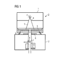
- FIG. 1 shows a conventional x-ray apparatus
- FIG. 2 shows one embodiment of an under-couch device in two different positions
- FIG. 3 shows one embodiment of an x-ray apparatus having an engaging mechanism
- FIG. 4 illustrates the functionality of one embodiment of the x-ray apparatus with an engaging mechanism
- FIG. 5 shows a front view of one embodiment of an under-couch device
- FIG. 6 shows a side view of one embodiment of an under-couch device
- FIG. 7 shows a first example of the positioning of a motor in one embodiment of an apparatus
- FIG. 8 shows a second example of the positioning of a motor
- FIG. 9 shows a front view of one embodiment of an under-couch device
- FIG. 10 shows one embodiment of an x-ray apparatus
- FIG. 11 shows a side view of one embodiment of an under-couch device.
- FIG. 1 shows an apparatus 3 for generating x-rays.
- the apparatus 3 includes an x-ray emitter 1 and an aperture housing 2 .
- the x-ray emitter 1 from which focus F x-rays emanate, includes a rough pre-aperture 5 and a beam window 4 .
- a pre-aperture 6 provided with the slots and elements 7 and 8 for determining a position of the focus F and an actual main aperture 10 for forming a useful x-ray beam bundle are integrated into the aperture housing 2 .
- a scattered radiation seal 9 also exists between the x-ray emitter 1 and the aperture housing 2 .
- the x-ray apparatus 3 radiates upwards (e.g., a position is rotated by 180 degrees with respect to FIG. 1 ).
- the x-ray apparatus 3 exhibits an expansion in the beam direction.
- the aperture structure is responsible for a minimum distance of the focus F from a patient being provided during operation. In conventional under-couch devices, this distance limits the possible lowering depth of the patient support and/or patient couch. As a result, access for the patient is made more difficult.
- the patient may climb onto a couch with a couch height of approximately 80 to 90 cm. This is difficult for many patients with respect to the size and/or state of health of the patient. To remedy this difficulty, present embodiments are explained in more detail below with the aid of FIG. 2 .
- FIG. 2 shows one embodiment of an under-couch device 20 in two different positions.
- a position, in which recordings take place, is shown on the left side.
- the x-ray emitter 1 is a certain distance from the floor and is arranged for fluoroscopy with respect to the patient support 11 .
- the patient support 11 is lowered as shown in the image to the right.
- the x-ray emitter 2 is lowered to the floor.
- the x-ray apparatus includes an area 19 that is accommodated when lowering the patient support 11 in a lower region 111 of the patient support 11 .
- the patient support 11 may therefore be lowered further than with conventional systems by about the thickness D of the lower area 111 .
- the patient support 11 is thus more easily accessible.
- FIG. 3 shows a mechanism used for the partial lowering of the x-ray apparatus.
- the x-ray tube 1 and the aperture housing 2 form an x-ray apparatus that may be lowered for the patient to climb on.
- An engaging lever 13 , a detent 12 (e.g., with an opening of approximately 30 mm) and a linear guide 14 are shown in FIG. 3 .
- the engaging lever 13 , the detent 12 , and the linear guide 14 are moved together with the x-ray apparatus 3 .
- the engaging lever 13 includes a ball bearing attached below.
- the engaging lever 13 has a diameter of 30 mm, for example.
- the latching lever 13 is also provided with a spring support 23 and is moveably mounted (e.g., pivotable about axis 24 ) so that the spring support 23 presses the lever 13 into the detent 12 in an engaged position.
- the detent 12 is a stationary component with respect to the patient support 11 .
- the mechanism is described with the aid of FIG. 4 .
- the x-ray apparatus with the engaging mechanism 21 is visible in the center of FIG. 4 . If the emitter is in the engaged position, the x-ray apparatus is in a normal working position. As indicated above right with respect to the entire system 20 , the patient support is moved downwards for patient access (e.g., arrow 22 ). The emitter 1 rests on the floor when the couch moves downwards.
- the downward movement provides that the force of the spring on the detent lever 13 is no longer adequate, and the lever is pressed out of the detent 12 .
- a ball bearing (not shown) that enables the leverage movement.
- the unit including emitter 1 , engaging lever 12 , linear guide 14 and spring support may therefore be moved upwards guided by the linear guide 14 . If the table is moved upwards again after positioning the patient, the emitter unit reengages on account of the dead weight. No displacement of the emitter outside of a zero degree position arises.
- FIG. 5 provides information relating to the space available and/or traveling distance.
- FIG. 5 shows the emitter 1 in the engaged position (e.g., extended to a maximum).
- Reference character 17 indicates the maximum upward travelling distance. The maximum upward travelling distance ends just below the detector loader 15 , which may traverse the couch from A to B.
- FIG. 6 shows a side view of the overall system, in which protection from x-ray radiation 18 is provided.
- FIG. 7 and FIG. 8 indicate possible positions for the motor-driven drive of the tubes.
- This drive is designated with reference character 19 .
- Different variants of a motor may be provided (e.g., a space-saving drum motor or a normal electric motor).
- the type of drive may be a spindle drive or a rack drive.
- the arrangement of the motor may be lateral to the aperture (e.g., on the rear ( FIG. 7 ) or adjacent to the aperture ( FIG. 8 ) when viewed from the front).
- FIG. 9 shows the entire system from the front having a possible motor position of the motor 9 .
- FIG. 10 is a front view of the x-ray apparatus
- FIG. 11 is a side view of the entire under-couch system.
- the apparatus is not restricted to the embodiments illustrated.
- other mechanisms than a purely mechanical one may be provided for engagement.
- Developments may include, for example, a sensor system that detects positions of the couch and triggers an unlocking mechanism using a control signal.
- the forces developing in the mechanical embodiment illustrated may, for example, be reduced when coming into contact with the floor.
- a safety system that prevents the x-ray tube from triggering if no unlocking and/or no engagement and thus no recording position of the x-ray emitter exists, may be applied.
Landscapes
- Physics & Mathematics (AREA)
- Engineering & Computer Science (AREA)
- Health & Medical Sciences (AREA)
- Spectroscopy & Molecular Physics (AREA)
- General Engineering & Computer Science (AREA)
- High Energy & Nuclear Physics (AREA)
- Biomedical Technology (AREA)
- Nuclear Medicine, Radiotherapy & Molecular Imaging (AREA)
- Pathology (AREA)
- Radiology & Medical Imaging (AREA)
- Life Sciences & Earth Sciences (AREA)
- Animal Behavior & Ethology (AREA)
- General Health & Medical Sciences (AREA)
- Public Health (AREA)
- Veterinary Medicine (AREA)
- Apparatus For Radiation Diagnosis (AREA)
Applications Claiming Priority (3)
| Application Number | Priority Date | Filing Date | Title |
|---|---|---|---|
| DE102011076876 | 2011-06-01 | ||
| DE102011076876.9A DE102011076876B4 (de) | 2011-06-01 | 2011-06-01 | Patientenbestrahlungsvorrichtung mit vereinfachtem Patientenzugang |
| DEDE102011076876.9 | 2011-06-01 |
Publications (2)
| Publication Number | Publication Date |
|---|---|
| US20120307979A1 US20120307979A1 (en) | 2012-12-06 |
| US9101762B2 true US9101762B2 (en) | 2015-08-11 |
Family
ID=47173212
Family Applications (1)
| Application Number | Title | Priority Date | Filing Date |
|---|---|---|---|
| US13/485,882 Active 2034-03-16 US9101762B2 (en) | 2011-06-01 | 2012-05-31 | Patient irradiation apparatus having simplified patient access |
Country Status (3)
| Country | Link |
|---|---|
| US (1) | US9101762B2 (de) |
| CN (1) | CN102805629B (de) |
| DE (1) | DE102011076876B4 (de) |
Citations (10)
| Publication number | Priority date | Publication date | Assignee | Title |
|---|---|---|---|---|
| US4024403A (en) * | 1976-03-19 | 1977-05-17 | General Electric Company | X-ray cardiovascular examination apparatus |
| US4293770A (en) * | 1979-11-29 | 1981-10-06 | General Electric Company | X-Ray table for obtaining longitudinal and lateral oblique cardiovascular views |
| US5416824A (en) * | 1993-05-13 | 1995-05-16 | Siemens Aktiengesellschaft | X-ray diagnostics apparatus |
| US5515415A (en) | 1993-07-27 | 1996-05-07 | Siemens Aktiengesellschaft | Medical apparatus permitting unimpeded patient access to the patient support table |
| WO1998027866A2 (en) | 1996-12-20 | 1998-07-02 | Koninklijke Philips Electronics N.V. | Medical apparatus including a patient table with a compact and rigid elevating mechanism |
| CN2342773Y (zh) | 1998-07-31 | 1999-10-13 | 上海医疗器械厂 | 适用于x射线机诊视床的x射线管组件翻转装置 |
| DE102005020898A1 (de) | 2005-05-04 | 2006-11-23 | Siemens Ag | Verfahren und Röntgeneinrichtung zur Durchleuchtung eines in variablem Abstand zu einer Röntgenquelle platzierbaren Patienten |
| CN1915172A (zh) | 2005-08-18 | 2007-02-21 | Ge医疗系统环球技术有限公司 | 检查床位置测量方法、下垂补偿方法和x射线ct设备 |
| US20090296891A1 (en) * | 2008-05-27 | 2009-12-03 | Franz Beimler | Positioning of an X-Ray Apparatus |
| US20110067179A1 (en) | 2009-09-24 | 2011-03-24 | Tobias Klemm | Patient support apparatus |
-
2011
- 2011-06-01 DE DE102011076876.9A patent/DE102011076876B4/de active Active
-
2012
- 2012-05-31 US US13/485,882 patent/US9101762B2/en active Active
- 2012-05-31 CN CN201210176571.1A patent/CN102805629B/zh active Active
Patent Citations (15)
| Publication number | Priority date | Publication date | Assignee | Title |
|---|---|---|---|---|
| US4024403A (en) * | 1976-03-19 | 1977-05-17 | General Electric Company | X-ray cardiovascular examination apparatus |
| US4293770A (en) * | 1979-11-29 | 1981-10-06 | General Electric Company | X-Ray table for obtaining longitudinal and lateral oblique cardiovascular views |
| US5416824A (en) * | 1993-05-13 | 1995-05-16 | Siemens Aktiengesellschaft | X-ray diagnostics apparatus |
| US5515415A (en) | 1993-07-27 | 1996-05-07 | Siemens Aktiengesellschaft | Medical apparatus permitting unimpeded patient access to the patient support table |
| WO1998027866A2 (en) | 1996-12-20 | 1998-07-02 | Koninklijke Philips Electronics N.V. | Medical apparatus including a patient table with a compact and rigid elevating mechanism |
| US5953776A (en) | 1996-12-20 | 1999-09-21 | U.S. Philips Corporation | Medical apparatus including a patient table with a compact and rigid elevating mechanism |
| CN2342773Y (zh) | 1998-07-31 | 1999-10-13 | 上海医疗器械厂 | 适用于x射线机诊视床的x射线管组件翻转装置 |
| DE102005020898A1 (de) | 2005-05-04 | 2006-11-23 | Siemens Ag | Verfahren und Röntgeneinrichtung zur Durchleuchtung eines in variablem Abstand zu einer Röntgenquelle platzierbaren Patienten |
| US20060269044A1 (en) | 2005-05-04 | 2006-11-30 | Jens Fehre | Method and x-ray apparatus for exposure of a patient who can be placed at a variable distance relative to an x-ray source |
| US7428295B2 (en) * | 2005-05-04 | 2008-09-23 | Siemens Aktiengesellschaft | Method and x-ray apparatus for exposure of a patient at variable distances relative to an x-ray source |
| CN1915172A (zh) | 2005-08-18 | 2007-02-21 | Ge医疗系统环球技术有限公司 | 检查床位置测量方法、下垂补偿方法和x射线ct设备 |
| US20090296891A1 (en) * | 2008-05-27 | 2009-12-03 | Franz Beimler | Positioning of an X-Ray Apparatus |
| DE102008025242A1 (de) | 2008-05-27 | 2009-12-03 | Siemens Aktiengesellschaft | Röntgenvorrichtung sowie Verfahren zum Verstellen einer Röntgenvorrichtung |
| US7938578B2 (en) | 2008-05-27 | 2011-05-10 | Siemens Aktiengesellschaft | Positioning of an x-ray apparatus |
| US20110067179A1 (en) | 2009-09-24 | 2011-03-24 | Tobias Klemm | Patient support apparatus |
Non-Patent Citations (2)
| Title |
|---|
| German Office Action dated Jan. 26, 2012 for corresponding German Patent Application No. DE 10 2011 076 876.9 with English translation. |
| Not in English-Only search report on p. 5 of 6 of Chinese action considered. Chinese Office Action for Chinese Application No. 201210176571.1, mailed Mar. 31, 2015, with German Translation. |
Also Published As
| Publication number | Publication date |
|---|---|
| DE102011076876B4 (de) | 2018-06-21 |
| CN102805629A (zh) | 2012-12-05 |
| DE102011076876A1 (de) | 2012-12-06 |
| CN102805629B (zh) | 2016-09-07 |
| US20120307979A1 (en) | 2012-12-06 |
Similar Documents
| Publication | Publication Date | Title |
|---|---|---|
| US9282936B2 (en) | Image diagnostic apparatus, X ray computed tomography apparatus, medical bed apparatus, and bed control method | |
| US20130077765A1 (en) | Digital radiography mechanical positioning system | |
| US11471117B2 (en) | Multiposition collimation device and x-ray imaging systems | |
| US9848841B2 (en) | X-ray stitching jig | |
| JPH05237086A (ja) | X線撮影装置 | |
| EP1702566B1 (de) | Armstütze für einen Apparat zur Erzeugung von Röntgenbildern | |
| US10993685B2 (en) | Device for remote fluoroscopy, nearby fluoroscopy and radiology | |
| JP6525768B2 (ja) | 乳房撮影装置 | |
| JP6608117B2 (ja) | マンモグラフィ装置、放射線画像撮影方法、及び放射線画像撮影プログラム | |
| US10463327B2 (en) | X-ray diagnostic apparatus, medical image diagnostic system and control method | |
| US9101762B2 (en) | Patient irradiation apparatus having simplified patient access | |
| JP4084217B2 (ja) | X線ct装置 | |
| JP6540399B2 (ja) | 放射線透視撮影装置 | |
| JP2009247391A (ja) | 医用画像診断装置 | |
| JP4574661B2 (ja) | X線ct装置 | |
| US8944681B2 (en) | Mobile X-ray machine with an anticollision device | |
| JPH0690949A (ja) | X線診断装置 | |
| US20210059621A1 (en) | X-ray image diagnostic apparatus | |
| JP2006197961A (ja) | 着座位置表示システム及びそれを用いた画像診断装置並びにx線ct装置 | |
| JP7354871B2 (ja) | 画像診断装置 | |
| US20240050049A1 (en) | Radiation protection device and radiographic imaging apparatus including the same | |
| EP4331493A1 (de) | Mammographiegerät | |
| WO2023199918A1 (ja) | 頭部画像取得装置及び頭部画像取得方法 | |
| JP2023070936A (ja) | X線コンピュータ断層撮影装置 | |
| JP6929680B2 (ja) | X線ctシステム |
Legal Events
| Date | Code | Title | Description |
|---|---|---|---|
| AS | Assignment |
Owner name: SIEMENS AKTIENGESELLSCHAFT, GERMANY Free format text: ASSIGNMENT OF ASSIGNORS INTEREST;ASSIGNORS:LUKAS, JOERG;WOEHRL, DIETER;REEL/FRAME:028793/0469 Effective date: 20120625 |
|
| FEPP | Fee payment procedure |
Free format text: PAYOR NUMBER ASSIGNED (ORIGINAL EVENT CODE: ASPN); ENTITY STATUS OF PATENT OWNER: LARGE ENTITY |
|
| STCF | Information on status: patent grant |
Free format text: PATENTED CASE |
|
| AS | Assignment |
Owner name: SIEMENS HEALTHCARE GMBH, GERMANY Free format text: ASSIGNMENT OF ASSIGNORS INTEREST;ASSIGNOR:SIEMENS AKTIENGESELLSCHAFT;REEL/FRAME:039271/0561 Effective date: 20160610 |
|
| MAFP | Maintenance fee payment |
Free format text: PAYMENT OF MAINTENANCE FEE, 4TH YEAR, LARGE ENTITY (ORIGINAL EVENT CODE: M1551); ENTITY STATUS OF PATENT OWNER: LARGE ENTITY Year of fee payment: 4 |
|
| MAFP | Maintenance fee payment |
Free format text: PAYMENT OF MAINTENANCE FEE, 8TH YEAR, LARGE ENTITY (ORIGINAL EVENT CODE: M1552); ENTITY STATUS OF PATENT OWNER: LARGE ENTITY Year of fee payment: 8 |
|
| AS | Assignment |
Owner name: SIEMENS HEALTHINEERS AG, GERMANY Free format text: ASSIGNMENT OF ASSIGNORS INTEREST;ASSIGNOR:SIEMENS HEALTHCARE GMBH;REEL/FRAME:066088/0256 Effective date: 20231219 |