US9059887B2 - Receiving device and receiving method for determining doppler frequency from pilot signals using OFDM - Google Patents
Receiving device and receiving method for determining doppler frequency from pilot signals using OFDM Download PDFInfo
- Publication number
- US9059887B2 US9059887B2 US13/870,572 US201313870572A US9059887B2 US 9059887 B2 US9059887 B2 US 9059887B2 US 201313870572 A US201313870572 A US 201313870572A US 9059887 B2 US9059887 B2 US 9059887B2
- Authority
- US
- United States
- Prior art keywords
- doppler frequency
- pilot signals
- fourier transform
- impulse responses
- inverse fourier
- Prior art date
- Legal status (The legal status is an assumption and is not a legal conclusion. Google has not performed a legal analysis and makes no representation as to the accuracy of the status listed.)
- Expired - Fee Related, expires
Links
Images


Classifications
-
- H—ELECTRICITY
- H04—ELECTRIC COMMUNICATION TECHNIQUE
- H04L—TRANSMISSION OF DIGITAL INFORMATION, e.g. TELEGRAPHIC COMMUNICATION
- H04L27/00—Modulated-carrier systems
- H04L27/26—Systems using multi-frequency codes
- H04L27/2601—Multicarrier modulation systems
- H04L27/2647—Arrangements specific to the receiver only
- H04L27/2649—Demodulators
- H04L27/26524—Fast Fourier transform [FFT] or discrete Fourier transform [DFT] demodulators in combination with other circuits for demodulation
- H04L27/26526—Fast Fourier transform [FFT] or discrete Fourier transform [DFT] demodulators in combination with other circuits for demodulation with inverse FFT [IFFT] or inverse DFT [IDFT] demodulators, e.g. standard single-carrier frequency-division multiple access [SC-FDMA] receiver or DFT spread orthogonal frequency division multiplexing [DFT-SOFDM]
-
- H—ELECTRICITY
- H04—ELECTRIC COMMUNICATION TECHNIQUE
- H04L—TRANSMISSION OF DIGITAL INFORMATION, e.g. TELEGRAPHIC COMMUNICATION
- H04L27/00—Modulated-carrier systems
- H04L27/26—Systems using multi-frequency codes
- H04L27/2601—Multicarrier modulation systems
- H04L27/2647—Arrangements specific to the receiver only
- H04L27/2649—Demodulators
- H04L27/265—Fourier transform demodulators, e.g. fast Fourier transform [FFT] or discrete Fourier transform [DFT] demodulators
-
- H—ELECTRICITY
- H04—ELECTRIC COMMUNICATION TECHNIQUE
- H04L—TRANSMISSION OF DIGITAL INFORMATION, e.g. TELEGRAPHIC COMMUNICATION
- H04L25/00—Baseband systems
- H04L25/02—Details ; arrangements for supplying electrical power along data transmission lines
- H04L25/0202—Channel estimation
- H04L25/0222—Estimation of channel variability, e.g. coherence bandwidth, coherence time, fading frequency
-
- H—ELECTRICITY
- H04—ELECTRIC COMMUNICATION TECHNIQUE
- H04L—TRANSMISSION OF DIGITAL INFORMATION, e.g. TELEGRAPHIC COMMUNICATION
- H04L27/00—Modulated-carrier systems
- H04L27/26—Systems using multi-frequency codes
- H04L27/2601—Multicarrier modulation systems
- H04L27/2647—Arrangements specific to the receiver only
- H04L27/2655—Synchronisation arrangements
- H04L27/2657—Carrier synchronisation
-
- H—ELECTRICITY
- H04—ELECTRIC COMMUNICATION TECHNIQUE
- H04L—TRANSMISSION OF DIGITAL INFORMATION, e.g. TELEGRAPHIC COMMUNICATION
- H04L5/00—Arrangements affording multiple use of the transmission path
- H04L5/003—Arrangements for allocating sub-channels of the transmission path
- H04L5/0048—Allocation of pilot signals, i.e. of signals known to the receiver
-
- H—ELECTRICITY
- H04—ELECTRIC COMMUNICATION TECHNIQUE
- H04L—TRANSMISSION OF DIGITAL INFORMATION, e.g. TELEGRAPHIC COMMUNICATION
- H04L27/00—Modulated-carrier systems
- H04L27/26—Systems using multi-frequency codes
- H04L27/2601—Multicarrier modulation systems
- H04L27/2647—Arrangements specific to the receiver only
- H04L27/2655—Synchronisation arrangements
- H04L27/2668—Details of algorithms
- H04L27/2673—Details of algorithms characterised by synchronisation parameters
- H04L27/2675—Pilot or known symbols
-
- H—ELECTRICITY
- H04—ELECTRIC COMMUNICATION TECHNIQUE
- H04L—TRANSMISSION OF DIGITAL INFORMATION, e.g. TELEGRAPHIC COMMUNICATION
- H04L27/00—Modulated-carrier systems
- H04L27/26—Systems using multi-frequency codes
- H04L27/2601—Multicarrier modulation systems
- H04L27/2647—Arrangements specific to the receiver only
- H04L27/2655—Synchronisation arrangements
- H04L27/2689—Link with other circuits, i.e. special connections between synchronisation arrangements and other circuits for achieving synchronisation
- H04L27/2695—Link with other circuits, i.e. special connections between synchronisation arrangements and other circuits for achieving synchronisation with channel estimation, e.g. determination of delay spread, derivative or peak tracking
Definitions
- the present invention relates to a receiving device and a receiving method for receiving OFDM signals.
- a communication system having an OFDM (Orthogonal Frequency Division Multiplexing) frame has been known and it has been adopted in ISDB-T (Integrated Services Digital Broadcasting-Terrestrial) of the Japanese integrated services digital broadcasting terrestrial standard.
- ISDB-T Integrated Services Digital Broadcasting-Terrestrial
- a receiving device moves in a Rayleigh environment in which multiply scattered waves due to a multipath are received, the received frequency varies irregularly due to the Doppler effect. Because of this, fluctuations in received frequency are taken into consideration for a receiving device and in a receiving device for terrestrial digital broadcasting, demodulation processing that has taken into consideration the influence of the Doppler shift, which is a phenomenon in which the carrier frequency shifts at the time of reception while moving, is performed.
- a difference between the frequency of a signal and the frequency of the signal having changed due to the Doppler shift is a Doppler frequency.
- SP scattered Pilot
- the pilot signals are arranged at 12-carrier intervals in the subcarrier (frequency) direction, which is the horizontal axis, and in the symbol (time) direction, the pilot signals are arranged so as to shift every three subcarriers between two successive symbols.
- a known technique hitherto which estimates the Doppler frequency applied to the carrier frequency by reception while moving using pilot signals extracted from a received signal after a Fourier transform.
- the second method it is common to find a phase rotation amount of two pilot signals with the same subcarrier number of the received signals of different symbols and then, to estimate the Doppler frequency therefrom.
- the second method is performed in the OFDM frame configuration, such as that in the terrestrial digital method, a difference in phase between the pilot signal of the current symbol and that of the symbol four symbols ahead thereof is found and the phase rotation amount is found therefrom.
- the second method if the Doppler frequency is large and the phase rotation amount exceeds ⁇ 180 degrees, it is no longer possible to find an accurate phase rotation amount. Because of this, there has been the problem that it is not possible to estimate an accurate Doppler frequency by the second method in the case where the Doppler frequency is large.
- the Doppler frequency is found based on the phase rotation amount of two pilot signals with different subcarrier numbers of the received signals of different symbols.
- impulse responses are found by performing an inverse Fourier transform on the two different pilot signals, respectively.
- peak positions of the impulse responses are found and the phase rotation amount of the two pilot signals at the peak positions is found.
- the amounts of frequency shift of both the pilot signals and the phase correction amounts derived from the delay amount at the peak positions are added.
- the Doppler frequency is estimated from the corrected phase rotation amount.
- the first method it is possible to use pilot signals with different subcarrier numbers, and therefore, it is possible to find a phase rotation amount less than four symbols and to obtain an accurate Doppler frequency even in the case where the Doppler frequency is large compared to that in the second method. Because of this, in the normal case, it is desirable to obtain a Doppler frequency by applying the first method rather than the second method.
- folding occurs at 84- ⁇ sec intervals corresponding to 1/12 of the OFDM symbol length in the impulse response found by an inverse Fourier transform of the pilot signal. Because of this, if a delay wave exists at the position of 84 ⁇ i ⁇ sec (i is an integer) corresponding to the folding, it is no longer possible to accurately find a phase correction amount or to perform phase correction, and therefore, there is the problem that the estimation precision of the Doppler frequency deteriorates.
- a receiving device of OFDM signals which calculates the Doppler frequency with precision and performs demodulation processing with reduced influence of the Doppler shift in the propagation path environment with a multipath, the delay amount of which is large, is realized.
- a receiving device for receiving OFDM signals in which arrangement of pilot signals changes with symbol time includes: an inverse Fourier transform unit configured to calculate an impulse response by performing an inverse Fourier transform on pilot signals included in a received signal, which is the OFDM signal having been received and subjected to a Fourier transform; a first Doppler frequency estimation unit configured to estimate a first Doppler frequency from a phase rotation amount at peak positions between impulse responses of pilot signals of different subcarriers of the impulse responses calculated by the inverse Fourier transform; a second Doppler frequency estimation unit configured to estimate a second Doppler frequency from a phase rotation amount between impulse responses of pilot signals of the same subcarrier of the impulse responses calculated by the inverse Fourier transform; and a Doppler frequency selection unit configured to select one of the first and the second Doppler frequency estimated by the first and the second Doppler frequency estimation unit.
- a receiving method for receiving OFDM signals in which arrangement of pilot signals changes with symbol time includes: calculating an impulse response by performing an inverse Fourier transform on pilot signals included in a received signal, which is the OFDM signal having been received and subjected to a Fourier transform; estimating a first Doppler frequency from a phase rotation amount at peak positions between impulse responses of pilot signals of different subcarriers of the impulse responses calculated by the inverse Fourier transform; estimating a second Doppler frequency from a phase rotation amount between impulse responses of pilot signals of the same subcarrier of the impulse responses calculated by the inverse Fourier transform; and selecting one of the first and the second Doppler frequency.
- FIG. 1 is a block diagram illustrating a general configuration of an OFDM receiving device of a first embodiment
- FIG. 2 is a diagram illustrating a configuration of the Doppler frequency estimation unit in the first embodiment
- FIG. 3 is a diagram illustrating a frame configuration example of an OFDM signal
- FIG. 4 is a diagram illustrating examples of acquired impulse responses in symbols #n, #n- 2 , and #n- 4 ;
- FIG. 5A to FIG. 5C are diagrams explaining a method for deriving a phase rotation amount ⁇ between the symbol #n and the symbol #n- 2 , which is performed by the two-symbol impulse response delay unit and the first phase deviation calculation unit;
- FIG. 6A to FIG. 6D are diagrams explaining a method for calculating a path delay amount in the case where the path delay amount at the peak position in the impulse response exceeds T/12;
- FIGS. 7A to 7E are diagrams explaining details of processing to find a delay amount at the peak position by the peak position specifying unit
- FIG. 8A to FIG. 8C are diagrams explaining calculation processing of the phase rotation amount (phase difference) ⁇ in the first phase deviation calculation unit in the case where the delay amount difference between the main wave and the delay wave is equal to T/12;
- FIG. 9A to FIG. 9C are diagrams explaining a method for deriving the phase rotation amount ⁇ between the symbol #n and the symbol #n- 4 , which is performed by the four-symbol impulse response delay unit and the second phase deviation calculation unit;
- FIG. 10 is a flowchart illustrating the operation of the receiving device of the first embodiment
- FIG. 11 is a diagram illustrating a configuration of the Doppler frequency estimation unit in a receiving device of a second embodiment
- FIGS. 12A to 12D are diagrams explaining a method for deriving the phase rotation amount ⁇ , which is performed by the second Doppler frequency estimation unit in the second embodiment.
- FIG. 1 is a block diagram illustrating a general configuration of an OFDM receiving device of a first embodiment.
- the OFDM receiving device has an antenna 11 , an RF band processing unit 12 , an A/D converter (ADC) 13 , an orthogonal demodulation unit 14 , a fast Fourier transform unit (FFT) 15 , a Doppler frequency estimation unit 16 , a transmission path estimation/equalization unit 17 , and a demodulation processing unit 18 .
- the orthogonal demodulation unit 14 , the fast Fourier transform unit (FFT) 15 , the Doppler frequency estimation unit 16 , the transmission path estimation/equalization unit 17 , and the demodulation processing unit 18 are implemented by, for example, software processing in a computer.
- the antenna 11 receives OFDM signals.
- the RF band processing unit 12 down-converts processing and processing of the RF band, such as orthogonal demodulation, on OFDM signals received by the antenna.
- the ADC 13 converts an analog signal down-converted in the RF band processing unit 12 into a digital signal.
- the orthogonal demodulation unit 14 demodulates a digital signal into a base band signal and generates I and Q signals.
- the FFT 15 generates a frequency signal X (f) by performing Fourier transform processing on the orthogonally demodulated I and Q signals.
- the Doppler frequency estimation unit 16 extracts pilot signals arranged in accordance with the frame configuration from the frequency signal X (f) and estimates a Doppler frequency and a frequency offset value based on the signals.
- the transmission path estimation/equalization unit 17 estimates the propagation path and equalization processing of the received signal X (f) while adaptively switching between estimation and equalization processing based on the Doppler frequency and the frequency offset value estimated by the Doppler frequency estimation unit 16 . Further, the frequency offset value is used to correct a local frequency at the orthogonal demodulation unit 14 in view of that it is generated by a shift in the local oscillation frequency at the orthogonal demodulation unit 14 .
- the demodulation processing unit 18 demaps a code point of an equalized signal, error correction processing, etc.
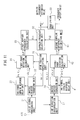
- FIG. 2 is a diagram illustrating a configuration of the Doppler frequency estimation unit 16 in the first embodiment.
- the Doppler frequency estimation unit 16 has a pilot signal recording unit 21 , an inverse Fourier transform unit (IFFT) 22 , a two-symbol impulse response delay unit 23 , a four-symbol impulse response delay unit 24 , a first phase deviation calculation unit 25 , and a second phase deviation calculation unit 26 .
- the Doppler frequency estimation unit 16 further has a time direction interpolation unit 27 , an inverse Fourier transform unit (IFFT) 28 , a peak position specifying unit 29 , a first Doppler frequency calculation unit 30 , a second Doppler frequency calculation unit 31 , a Doppler frequency selection unit 32 , and an averaging circuit 33 .
- IFFT inverse Fourier transform unit
- the two-symbol impulse response delay unit 23 , the first phase deviation calculation unit 25 , the peak position specifying unit 29 , and the first Doppler frequency calculation unit 30 form a first Doppler frequency estimation unit.
- the first Doppler frequency estimation unit includes the time direction interpolation unit 27 and the inverse fast Fourier transform unit (IFFT) 28 .
- the first Doppler frequency estimation unit estimates a first Doppler frequency Fd 1 from the phase rotation amount at the peak positions between the impulse responses of pilot signals of different subcarriers of the impulse responses calculated by an inverse Fourier transform.
- the four-symbol impulse response delay unit 24 , the second phase deviation calculation unit 26 , and the second Doppler frequency calculation unit 31 form a second Doppler frequency estimation unit.
- the second Doppler frequency estimation unit estimates a second Doppler frequency Fd 2 from the phase rotation amount between the impulse responses of pilot signals of the same subcarrier of the impulse responses calculated by an inverse Fourier transform.
- FIG. 3 is a diagram illustrating a frame configuration example of an OFDM signal.
- an OFDM signal has a signal group in the form of a matrix including a plurality of subcarriers with different frequencies and a plurality of symbols at each of successive times. Symbols are arranged in the time direction, and therefore, the time of each symbol is referred to as a symbol time.
- the symbol length (number of symbols ⁇ time) is just an integer multiple of each subcarrier. In a certain symbol, each subcarrier is in a certain phase and if the symbol changes, the phase rotation amount of each subcarrier also changes. In FIG.
- the subcarrier represented by a black circle (Ds) is a subcarrier including a pilot signal and in one symbol, it is inserted into every 12 subcarriers and in the next neighboring symbol, it is inserted into every 12 subcarriers shifted by three subcarriers, and so on.
- the pilot signal recording unit 21 extracts pilot signals of a subcarrier group subjected to a Fourier transform by the FFT 15 .
- the inverse Fourier transform unit 22 performs an inverse Fourier transform on the pilot signals output from the pilot signal recording unit 21 .
- an impulse response is calculated.
- FIG. 4 is a diagram illustrating examples of acquired impulse responses in symbols #n, #n- 2 , and #n- 4 .
- a subcarrier is sometimes abbreviated simply to a carrier.
- the pilot signal is inserted into the same carrier at every four symbols, and therefore, #n and #n- 4 are a pilot signal group configured by the same carrier numbers and #n and #n- 2 are configured by pilot signal groups between which the frequencies are shifted by an amount corresponding to six carriers.
- #n and #n- 4 are a pilot signal group configured by the same carrier numbers
- #n and #n- 2 are configured by pilot signal groups between which the frequencies are shifted by an amount corresponding to six carriers.
- This impulse response indicates the multipath response of the propagation path, and therefore, is also referred to as a delay profile.
- phase rotation is caused due to the influence of fading and the amplitudes and phases of impulse responses between different symbols become different values.
- the phase rotation amount at this time is proportional to the Doppler frequency caused in the carrier wave. Because of this, it is possible to find the Doppler frequency from the phase rotation amount of the impulse response between symbols during a fixed period of time.
- FIG. 5A to FIG. 5C are diagrams explaining a method for deriving a phase rotation amount ⁇ between the symbol #n and the symbol #n- 2 , which is performed by the two-symbol impulse response delay unit 23 and the first phase deviation calculation unit 25 .
- FIG. 5A illustrates an impulse response of the symbol #n- 2
- FIG. 5B illustrates an impulse response of the symbol #n
- FIG. 5C illustrates a phase difference ⁇ due to a difference between positions of the pilot signals and the phase rotation amount ⁇ due to fading, respectively.
- the two-symbol impulse response delay unit 23 delays the impulse response of the symbol #n- 2 found by the inverse Fourier transform unit 22 by an amount corresponding to two symbols and outputs it to the first phase deviation calculation unit 25 .
- the first phase deviation calculation unit 25 receives the impulse response of the symbol #n found by the inverse Fourier transform unit 22 and the impulse response of the symbol #n- 2 delayed by an amount corresponding to two symbols by the two-symbol impulse response delay unit 23 .
- the first phase deviation calculation unit 25 compares the two impulse responses and finds peak phase amounts ⁇ n ⁇ 2 and ⁇ n at peak positions K of power in the impulse responses, respectively, and a phase difference between them.
- the phase difference ⁇ is proportional to the frequency of the pilot signal and the delay amount at a peak position #P of the impulse response. Because of this, the path delay amount at the peak position #P is found and the phase difference ⁇ corresponding thereto is calculated by calculation or using a table, etc.
- An impulse response h (n, ⁇ ) of the pilot signal is the signals at 12-carrier intervals subjected to the inverse Fourier transform, and therefore, the impulse response can be measured only to 1/12 of an OFDM symbol length T.
- FIG. 6A to FIG. 6D are diagrams explaining a method for calculating a path delay amount in the case where the path delay amount at the peak position in the impulse response exceeds T/12.
- FIG. 6A illustrates an OFDM frame
- FIG. 6B illustrates a path delay amount exceeding T/12 in the impulse response
- FIG. 6C illustrates a frame configuration in which the pilot signals are interpolated in the time direction
- FIG. 6D illustrates a measurable range in the case where interpolation is performed.
- a delay wave whose path delay amount at the peak position exceeds T/12 produces a virtual image at a position of folding at T/12 and it is not possible to obtain an accurate delay amount.
- an impulse response h′ (n, ⁇ ) is used, which is derived by interpolating the pilot signals in the time direction and subjecting the carrier group with three-carrier intervals of the pilot signal plus interpolation value to an inverse Fourier transform.
- the time direction interpolation unit 27 performs interpolation in the time (symbol) direction for the OFDM signal from the pilot signal storage unit 21 .
- the inverse Fourier transform unit 28 calculates h′ (n, ⁇ ) by performing an inverse Fourier transform on the interpolated signals.
- This impulse response is obtained by an inverse Fourier transform at three-carrier intervals, and therefore, it is possible to measure the impulse response to 1 ⁇ 3 of the OFDM symbol length T. Then, by matching the two impulse responses, the delay amount at the peak position #P is found. This method is widely known, and therefore, is briefly explained.
- FIGS. 7A to 7E are diagrams explaining details of processing to find a delay amount at the peak position by the peak position specifying unit 29 .
- FIG. 7A illustrates a case where the path delay amount at the peak position #P is ⁇ p and ⁇ p>T/12. As illustrated in FIG. 7B , in this case, folding occurs in the impulse response (n, ⁇ ) and a path is observed at the position where the delay amount is X.
- the path delay amount of the maximum path of the impulse response h (n, ⁇ ) is X
- the first phase deviation calculation unit 25 calculates the phase rotation amount (phase difference) ⁇ by taking into consideration the peak position and the delay amount specified by the peak position specifying unit 29 .
- the first Doppler frequency calculation unit 30 calculates the first Doppler frequency Fd 1 based on the phase rotation amount (phase difference) ⁇ calculated by the first phase deviation calculation unit 25 .
- FIG. 8A to FIG. 8C are diagrams explaining calculation processing of the phase rotation amount (phase difference) ⁇ in the first phase deviation calculation unit 25 in the case where the delay amount difference between the main wave and the delay wave is equal to T/12.
- FIG. 9A to FIG. 9C are diagrams explaining a method for deriving the phase rotation amount ⁇ between the symbol #n and the symbol #n- 4 , which is performed by the four-symbol impulse response delay unit 24 and the second phase deviation calculation unit 26 .
- FIG. 9A illustrates the impulse response of the symbol #n- 4
- FIG. 9B illustrates the impulse response of the symbol #n
- FIG. 9C illustrates the phase rotation amount ⁇ due to fading, respectively.
- the 4-symbol impulse response delay unit 24 delays the impulse response of the symbol #n- 4 found by the inverse Fourier transform unit 22 by an amount corresponding to four symbols and outputs it to the second phase deviation calculation unit 26 .
- the second phase deviation calculation unit 26 receives the impulse response of the symbol #n found by the inverse Fourier transform unit 22 and the impulse response of the symbol #n- 4 delayed by an amount corresponding to four symbols by the 4-symbol impulse response delay unit 24 .
- the second phase deviation calculation unit 26 compares the two impulse responses and finds the peak phase amounts ⁇ n ⁇ 4 and ⁇ n at the peak positions K of power in the impulse responses, respectively, and a phase different therebetween.
- the peak phase difference is the phase rotation amount ⁇ due to fading.
- the second Doppler frequency calculation unit 31 calculates the second Doppler frequency Fd 2 based on the phase rotation amount (phase difference) ⁇ calculated by the second phase deviation calculation unit 26 .
- the second phase deviation calculation unit 26 finds the phase rotation at four-symbol intervals, and therefore, if the Doppler frequency is large, the phase rotation amount exceeds ⁇ 180 degrees. In this case, it is no longer possible for the second phase deviation calculation unit 26 to find the accurate phase rotation amount (phase difference) ⁇ and it is no longer possible for the second Doppler frequency calculation unit 31 to calculate the accurate second Doppler frequency Fd 2 .
- the Doppler frequency estimation unit 16 selects one of the first Doppler frequency Fd 1 calculated by the first Doppler frequency calculation unit 30 and the second Doppler frequency Fd 2 calculated by the second Doppler frequency calculation unit 31 , which is more reliable.
- the first Doppler frequency estimation unit uses the pilot signals with different subcarrier numbers, and therefore, it is possible to find the phase rotation amount less than four symbols and to obtain an accurate Doppler frequency even when the Doppler frequency is large. Consequently, in the present embodiment, in the case where the first Doppler frequency Fd 1 estimated by the first Doppler frequency estimation unit is reliable, the first Doppler frequency Fd 1 is adopted. Then, in the case where the reliability of the first Doppler frequency Fd 1 deteriorates as described above, whether the second Doppler frequency Fd 2 estimated by the second Doppler frequency estimation unit can be relied upon, and if it can be relied upon, the second Doppler frequency Fd 2 is adopted. If the second Doppler frequency Fd 2 is not relied upon, the first Doppler frequency Fd 1 is adopted.
- FIG. 10 is a flowchart illustrating the operation of the receiving device of the first embodiment.
- the first Doppler frequency estimation unit acquires the first Doppler frequency Fd 1 and the second Doppler frequency estimation unit acquires the second Doppler frequency Fd 2 , respectively. Further, the time direction storage unit 27 and the inverse Fourier transform unit 28 acquire the impulse response h′ (n, ⁇ ) from the pilot signals subjected to time interpolation.
- the Doppler frequency selection unit 32 acquires a maximum delay amount ⁇ MAX of the path from the impulse response h′ (n, ⁇ ).
- the Doppler frequency selection unit 32 determines whether the maximum delay amount ⁇ MAX of the path exceeds T/12 and if it exceeds, the procedure proceeds to step S 14 and if not, the procedure proceeds to step S 16 .
- the maximum delay amount ⁇ MAX of the path does not exceed T/12
- the first Doppler frequency Fd 1 can be relied upon, and therefore, the first Doppler frequency Fd 1 is adopted at step S 16 .
- step S 14 whether the second Doppler frequency Fd 2 is equal to or less than a predetermined value is determined and if it is equal to or less than the predetermined value, the procedure proceeds to step S 15 and if not, the procedure proceeds to step S 16 .
- the second Doppler frequency Fd 2 is equal to or less than the predetermined value
- the second Doppler frequency Fd 2 can be relied upon, and therefore, the second Doppler frequency Fd 2 is adopted.
- the first Doppler frequency Fd 1 is adopted at step S 16 .
- the equalization circuit 33 calculates a frequency offset from the Doppler frequency selected by the Doppler frequency selection unit 32 .
- an offset occurs in transition of the received frequency.
- the center frequency of the carrier frequency shifts from fc. If a frequency transition exists, the Doppler frequency that is estimated actually tends to become an estimated value larger than an estimated value fd of the original Doppler frequency. Because of this, the Doppler frequency selected by the Doppler frequency selection unit 32 , from which the frequency offset calculated by the equalization circuit 32 is subtracted, is taken to be the final Doppler frequency estimated value.
- FIG. 11 is a diagram illustrating a configuration of the Doppler frequency estimation unit 16 in a receiving device of a second embodiment.
- the receiving device of the second embodiment differs from the receiving device of the first embodiment only in the Doppler frequency estimation unit 16 and other parts are the same as those of the first embodiment.
- the Doppler frequency estimation unit 16 in the second embodiment differs in that the second Doppler frequency estimation unit differs from that of the first embodiment, and other parts are the same.
- the second Doppler frequency estimation unit in the second embodiment includes a two-symbol impulse response delay unit 41 , a second phase deviation calculation unit 42 , and a second Doppler frequency calculation unit 43 .
- the inverse Fourier transform unit 28 performs an inverse Fourier transform on the carrier signal group output from the time direction interpolation unit 27 and including the pilot signals and the interpolated pilot signals used for interpolation of the pilot signals as illustrated in FIG. 6(C) , and outputs the impulse response h′ (n, ⁇ ).
- the two-symbol impulse response delay unit 41 delays the impulse response h′ (n, ⁇ ) by an amount corresponding to two symbols and outputs a two-symbol delayed impulse response h′ (n- 2 , ⁇ ).
- the second phase deviation calculation unit 42 calculates a phase difference ⁇ 02 between the impulse response h′ (n, ⁇ ) output from the inverse Fourier transform unit 28 and the two-symbol delayed impulse response h′ (n- 2 , ⁇ ) output from the two-symbol impulse response delay unit 41 .
- the second Doppler frequency calculation unit 43 calculates the second Doppler frequency Fd 2 from the phase difference ⁇ 2 as in the first embodiment.
- FIGS. 12A to 12D are diagrams explaining a method for deriving the phase rotation amount ⁇ , which is performed by the second Doppler frequency estimation unit in the second embodiment.
- FIG. 12A illustrates a carrier signal group including pilot signals and interpolated pilot signals used for interpolation of the pilot signals.
- FIG. 12B illustrates the two-symbol delayed impulse response h′ (n- 2 , ⁇ ) and
- FIG. 12C illustrates the impulse response h′ (n, ⁇ ).
- FIG. 12D illustrates the phase rotation amount ⁇ due to fading.
- the interpolation value after interpolation in the time direction is inserted at three-carrier intervals in the carrier direction and it is possible to make use of the same subcarrier regardless of the symbol (time) and phase correction does not need to be performed in the processing to calculate the phase rotation amount ⁇ . Because of this, it is possible to set the intervals of the phase rotation calculation of the impulse response to four symbols or less. In the configuration of FIG. 11 , an example of two-symbol intervals is illustrated, however, other intervals may be accepted.
Abstract
Description
- [Patent Document 1] Japanese Laid Open Patent Document No. 2005-286636
- [Patent Document 2] Japanese Laid Open Patent Document No. 2010-268274
- [Patent Document 3] Japanese Laid Open Patent Document No. 2010-268044
- [Patent Document 4] Japanese Laid Open Patent Document No. 2010-062865
- [Patent Document 5] Japanese Laid Open Patent Document No. 2010-288178
- [Non-Patent Document 1] D. Jitsukawa, et. al.: “Accurate Doppler frequency detection for OFDM”, IEICE, General Conference 2004, B-5-77
Δθ=peak phase difference−Θ=θn−θn−2−Θ.
Claims (6)
Applications Claiming Priority (2)
| Application Number | Priority Date | Filing Date | Title |
|---|---|---|---|
| JP2012-107558 | 2012-05-09 | ||
| JP2012107558A JP5865172B2 (en) | 2012-05-09 | 2012-05-09 | Receiving apparatus and receiving method |
Publications (2)
| Publication Number | Publication Date |
|---|---|
| US20130301759A1 US20130301759A1 (en) | 2013-11-14 |
| US9059887B2 true US9059887B2 (en) | 2015-06-16 |
Family
ID=49548605
Family Applications (1)
| Application Number | Title | Priority Date | Filing Date |
|---|---|---|---|
| US13/870,572 Expired - Fee Related US9059887B2 (en) | 2012-05-09 | 2013-04-25 | Receiving device and receiving method for determining doppler frequency from pilot signals using OFDM |
Country Status (2)
| Country | Link |
|---|---|
| US (1) | US9059887B2 (en) |
| JP (1) | JP5865172B2 (en) |
Families Citing this family (3)
| Publication number | Priority date | Publication date | Assignee | Title |
|---|---|---|---|---|
| JP2015207816A (en) * | 2014-04-17 | 2015-11-19 | 富士通株式会社 | Receiver, reception method, and wireless communication system |
| US11489598B2 (en) * | 2016-04-26 | 2022-11-01 | Rf Dsp Inc | Over-the-air channel state information acquirement for a massive MIMO channel emulator with over-the-air connection |
| EP3264702B1 (en) * | 2016-06-27 | 2019-01-09 | Telefonica, S.A. | A method to generate a wireless waveform for use in a wireless communication system, a wireless communication system and computer program products thereof |
Citations (22)
| Publication number | Priority date | Publication date | Assignee | Title |
|---|---|---|---|---|
| US20040190657A1 (en) * | 2003-02-21 | 2004-09-30 | Hiroyuki Seki | Communications device with doppler frequency estimation functions |
| JP2005286636A (en) | 2004-03-29 | 2005-10-13 | Sanyo Electric Co Ltd | Digital broadcast receiver |
| US20060269016A1 (en) * | 2005-05-27 | 2006-11-30 | Mediaphy Corporation | Adaptive interpolator for channel estimation |
| US20070030798A1 (en) * | 2005-07-15 | 2007-02-08 | Sony Corporation | Doppler frequency calculating apparatus and method and OFDM demodulating apparatus |
| US20080075186A1 (en) * | 2006-09-12 | 2008-03-27 | Sony Corporation | OFDM receiver and OFDM signal receiving method |
| US20080101490A1 (en) * | 2006-09-12 | 2008-05-01 | Sony Corporation | OFDM receiver and OFDM signal receiving method |
| US20080165871A1 (en) * | 2005-03-01 | 2008-07-10 | Akira Kisoda | Ofdm Receiver, Integrated Circuit And Receiving Method |
| US20080192843A1 (en) * | 2007-02-12 | 2008-08-14 | Roy Tenny | Video channel estimation |
| US20090207956A1 (en) * | 2006-08-21 | 2009-08-20 | Tomohiro Kimura | Receiver, integrated circuit, and reception method |
| US20090323789A1 (en) * | 2008-04-28 | 2009-12-31 | Newport Media, Inc. | Doppler Frequency Estimation in Wireless Communication Systems |
| JP2010062865A (en) | 2008-09-03 | 2010-03-18 | Fujitsu Ltd | Demodulator |
| US20100128823A1 (en) * | 2008-11-21 | 2010-05-27 | Semiconductor Technology Academic Research Center | Doppler frequency estimating device, receiving device, recording medium and doppler frequency estimating method |
| JP2010268044A (en) | 2009-05-12 | 2010-11-25 | Fujitsu Ltd | Receiving device |
| JP2010268274A (en) | 2009-05-15 | 2010-11-25 | Fujitsu Ltd | Semiconductor integrated circuit and reception signal processing method |
| JP2010288178A (en) | 2009-06-15 | 2010-12-24 | Fujitsu Ltd | Semiconductor integrated circuit and method of processing received signal |
| US20110064163A1 (en) * | 2009-09-11 | 2011-03-17 | Amlogic Co., Ltd. | Methods and Apparatuses for Channel Estimation of OFDM Systems to Combat Multipath Fading |
| US20110216808A1 (en) * | 2001-10-17 | 2011-09-08 | Nortel Networks Limited | Scattered pilot pattern and channel estimation method for mimo-ofdm systems |
| US8064507B1 (en) * | 2008-11-24 | 2011-11-22 | Qualcomm Atheros, Inc. | System and method for channel estimation |
| US20110310945A1 (en) * | 2009-02-25 | 2011-12-22 | Kyocera Corporation | Radio communication apparatus and radio communication method |
| US20120020427A1 (en) * | 2009-01-16 | 2012-01-26 | Alibis Systems Sàrl | Interpolated channel estimation for mobile ofdm systems |
| US8149905B1 (en) * | 2008-11-24 | 2012-04-03 | Qualcomm Atheros, Inc. | System and method for doppler frequency estimation |
| US20130121392A1 (en) * | 2011-11-15 | 2013-05-16 | Steven C. Thompson | OFDM Receiver With Time Domain Channel Estimation |
Family Cites Families (3)
| Publication number | Priority date | Publication date | Assignee | Title |
|---|---|---|---|---|
| GB2412552A (en) * | 2004-03-26 | 2005-09-28 | Sony Uk Ltd | Receiver |
| JP5344984B2 (en) * | 2009-04-28 | 2013-11-20 | 三菱電機株式会社 | Moving speed detection device and moving speed detection method |
| JP2011223546A (en) * | 2010-03-26 | 2011-11-04 | Fujitsu Ltd | Reception device |
-
2012
- 2012-05-09 JP JP2012107558A patent/JP5865172B2/en not_active Expired - Fee Related
-
2013
- 2013-04-25 US US13/870,572 patent/US9059887B2/en not_active Expired - Fee Related
Patent Citations (22)
| Publication number | Priority date | Publication date | Assignee | Title |
|---|---|---|---|---|
| US20110216808A1 (en) * | 2001-10-17 | 2011-09-08 | Nortel Networks Limited | Scattered pilot pattern and channel estimation method for mimo-ofdm systems |
| US20040190657A1 (en) * | 2003-02-21 | 2004-09-30 | Hiroyuki Seki | Communications device with doppler frequency estimation functions |
| JP2005286636A (en) | 2004-03-29 | 2005-10-13 | Sanyo Electric Co Ltd | Digital broadcast receiver |
| US20080165871A1 (en) * | 2005-03-01 | 2008-07-10 | Akira Kisoda | Ofdm Receiver, Integrated Circuit And Receiving Method |
| US20060269016A1 (en) * | 2005-05-27 | 2006-11-30 | Mediaphy Corporation | Adaptive interpolator for channel estimation |
| US20070030798A1 (en) * | 2005-07-15 | 2007-02-08 | Sony Corporation | Doppler frequency calculating apparatus and method and OFDM demodulating apparatus |
| US20090207956A1 (en) * | 2006-08-21 | 2009-08-20 | Tomohiro Kimura | Receiver, integrated circuit, and reception method |
| US20080075186A1 (en) * | 2006-09-12 | 2008-03-27 | Sony Corporation | OFDM receiver and OFDM signal receiving method |
| US20080101490A1 (en) * | 2006-09-12 | 2008-05-01 | Sony Corporation | OFDM receiver and OFDM signal receiving method |
| US20080192843A1 (en) * | 2007-02-12 | 2008-08-14 | Roy Tenny | Video channel estimation |
| US20090323789A1 (en) * | 2008-04-28 | 2009-12-31 | Newport Media, Inc. | Doppler Frequency Estimation in Wireless Communication Systems |
| JP2010062865A (en) | 2008-09-03 | 2010-03-18 | Fujitsu Ltd | Demodulator |
| US20100128823A1 (en) * | 2008-11-21 | 2010-05-27 | Semiconductor Technology Academic Research Center | Doppler frequency estimating device, receiving device, recording medium and doppler frequency estimating method |
| US8064507B1 (en) * | 2008-11-24 | 2011-11-22 | Qualcomm Atheros, Inc. | System and method for channel estimation |
| US8149905B1 (en) * | 2008-11-24 | 2012-04-03 | Qualcomm Atheros, Inc. | System and method for doppler frequency estimation |
| US20120020427A1 (en) * | 2009-01-16 | 2012-01-26 | Alibis Systems Sàrl | Interpolated channel estimation for mobile ofdm systems |
| US20110310945A1 (en) * | 2009-02-25 | 2011-12-22 | Kyocera Corporation | Radio communication apparatus and radio communication method |
| JP2010268044A (en) | 2009-05-12 | 2010-11-25 | Fujitsu Ltd | Receiving device |
| JP2010268274A (en) | 2009-05-15 | 2010-11-25 | Fujitsu Ltd | Semiconductor integrated circuit and reception signal processing method |
| JP2010288178A (en) | 2009-06-15 | 2010-12-24 | Fujitsu Ltd | Semiconductor integrated circuit and method of processing received signal |
| US20110064163A1 (en) * | 2009-09-11 | 2011-03-17 | Amlogic Co., Ltd. | Methods and Apparatuses for Channel Estimation of OFDM Systems to Combat Multipath Fading |
| US20130121392A1 (en) * | 2011-11-15 | 2013-05-16 | Steven C. Thompson | OFDM Receiver With Time Domain Channel Estimation |
Non-Patent Citations (4)
| Title |
|---|
| Daisuke Jitsukawa et al., "Accurate Doppler frequency detection for OFDM", Fujitsu Laboratories Ltd., p. 564, 2004. |
| Hayashi, H.; Okamoto, E.; Iwanami, Y., "A fast fading channel estimation scheme for OFDM with sparse and scattered pilot symbols," Intelligent Signal Processing and Communication Systems, 2009. ISPACS 2009. International Symposium on , vol., no., pp. 154,157, Jan. 7-9, 2009. * |
| Lihua Yang; Guangliang Ren; Zhiliang Qiu, "A Novel Doppler Frequency Offset Estimation Method for DVB-T System in HST Environment," Broadcasting, IEEE Transactions on , vol. 58, No. 1, pp. 139,143, Mar. 2012. * |
| Yucek, T.; Tannious, R.M.A.; Arslan, H., "Doppler spread estimation for wireless OFDM systems," Advances in Wired and Wireless Communication, 2005 IEEE/Sarnoff Symposium on , vol., No., pp. 233,236, Apr. 18-19, 2005. * |
Also Published As
| Publication number | Publication date |
|---|---|
| JP2013236253A (en) | 2013-11-21 |
| US20130301759A1 (en) | 2013-11-14 |
| JP5865172B2 (en) | 2016-02-17 |
Similar Documents
| Publication | Publication Date | Title |
|---|---|---|
| US8064328B2 (en) | Channel estimation device | |
| US8891491B2 (en) | Method of processing signals and a signal processor | |
| US9065717B2 (en) | Receiver and synchronization correcting method | |
| EP1780921A1 (en) | Disturbing signal detection device and ofdm reception device using the same | |
| US8837648B2 (en) | OFDM communication reception device | |
| JP4215084B2 (en) | Equalizer and equalization method | |
| US8199845B2 (en) | Up-link SDMA receiver for WiMAX | |
| JP2006140987A (en) | Reception apparatus | |
| KR20070079294A (en) | Symbol timing estimation in ofdma systems | |
| US9059887B2 (en) | Receiving device and receiving method for determining doppler frequency from pilot signals using OFDM | |
| US9774484B2 (en) | Receiver controller | |
| JP5109878B2 (en) | Demodulator | |
| WO2017104139A1 (en) | Propagation path estimation method | |
| JP5319384B2 (en) | Receiver | |
| US8238272B2 (en) | Frequency division multiplex transmission signal receiving apparatus | |
| JP4847850B2 (en) | OFDM receiver | |
| JP5566223B2 (en) | Diversity receiving apparatus and diversity receiving method | |
| JP2004159084A (en) | Ofdm reception device for estimating transmission path | |
| JP5495976B2 (en) | OFDM signal receiver | |
| KR100952935B1 (en) | Channel estimation device, OFDM receiving apparatus comprising the same estimation device and method of estimating channel | |
| KR101060489B1 (en) | An improved channel estimator and channel estimation method using improved lattice interpolation, and an ODF receiver including the device | |
| JP2023103804A (en) | Radio communication device and radio communication method | |
| KR20140106894A (en) | Timing synchronization method and apparatus, and received signal demodulation method and apparatus in orthogonal frequency division multiplexing system |
Legal Events
| Date | Code | Title | Description |
|---|---|---|---|
| AS | Assignment |
Owner name: FUJITSU SEMICONDUCTOR LIMITED, JAPAN Free format text: ASSIGNMENT OF ASSIGNORS INTEREST;ASSIGNORS:UMEDA, MASATAKA;ADACHI, NAOTO;REEL/FRAME:030347/0611 Effective date: 20130214 Owner name: FUJITSU LIMITED, JAPAN Free format text: ASSIGNMENT OF ASSIGNORS INTEREST;ASSIGNORS:UMEDA, MASATAKA;ADACHI, NAOTO;REEL/FRAME:030347/0611 Effective date: 20130214 |
|
| AS | Assignment |
Owner name: SOCIONEXT INC., JAPAN Free format text: ASSIGNMENT OF ASSIGNORS INTEREST;ASSIGNOR:FUJITSU SEMICONDUCTOR LIMITED;REEL/FRAME:035498/0324 Effective date: 20150302 |
|
| STCF | Information on status: patent grant |
Free format text: PATENTED CASE |
|
| FEPP | Fee payment procedure |
Free format text: MAINTENANCE FEE REMINDER MAILED (ORIGINAL EVENT CODE: REM.); ENTITY STATUS OF PATENT OWNER: LARGE ENTITY |
|
| LAPS | Lapse for failure to pay maintenance fees |
Free format text: PATENT EXPIRED FOR FAILURE TO PAY MAINTENANCE FEES (ORIGINAL EVENT CODE: EXP.); ENTITY STATUS OF PATENT OWNER: LARGE ENTITY |
|
| STCH | Information on status: patent discontinuation |
Free format text: PATENT EXPIRED DUE TO NONPAYMENT OF MAINTENANCE FEES UNDER 37 CFR 1.362 |
|
| FP | Lapsed due to failure to pay maintenance fee |
Effective date: 20190616 |