US9034498B2 - Secondary battery - Google Patents
Secondary battery Download PDFInfo
- Publication number
- US9034498B2 US9034498B2 US13/231,858 US201113231858A US9034498B2 US 9034498 B2 US9034498 B2 US 9034498B2 US 201113231858 A US201113231858 A US 201113231858A US 9034498 B2 US9034498 B2 US 9034498B2
- Authority
- US
- United States
- Prior art keywords
- case
- secondary battery
- disposed
- identifying tape
- electrolytic solution
- Prior art date
- Legal status (The legal status is an assumption and is not a legal conclusion. Google has not performed a legal analysis and makes no representation as to the accuracy of the status listed.)
- Expired - Fee Related, expires
Links
- 239000008151 electrolyte solution Substances 0.000 claims abstract description 67
- 239000000463 material Substances 0.000 claims abstract description 62
- 238000002845 discoloration Methods 0.000 claims abstract description 40
- 239000000853 adhesive Substances 0.000 claims abstract description 23
- 230000001070 adhesive effect Effects 0.000 claims abstract description 23
- 238000007789 sealing Methods 0.000 claims description 47
- 239000010410 layer Substances 0.000 claims description 39
- 229910052751 metal Inorganic materials 0.000 claims description 14
- 239000002184 metal Substances 0.000 claims description 14
- 239000000049 pigment Substances 0.000 claims description 5
- 229920000642 polymer Polymers 0.000 claims description 5
- 230000008859 change Effects 0.000 claims description 3
- 239000011247 coating layer Substances 0.000 claims description 3
- HBBGRARXTFLTSG-UHFFFAOYSA-N Lithium ion Chemical compound [Li+] HBBGRARXTFLTSG-UHFFFAOYSA-N 0.000 description 10
- 229910001416 lithium ion Inorganic materials 0.000 description 10
- WHXSMMKQMYFTQS-UHFFFAOYSA-N Lithium Chemical compound [Li] WHXSMMKQMYFTQS-UHFFFAOYSA-N 0.000 description 8
- 239000011888 foil Substances 0.000 description 8
- 229910052744 lithium Inorganic materials 0.000 description 8
- 230000004048 modification Effects 0.000 description 7
- 238000012986 modification Methods 0.000 description 7
- 230000000052 comparative effect Effects 0.000 description 4
- 239000003792 electrolyte Substances 0.000 description 3
- -1 polypropylene Polymers 0.000 description 3
- 229920002126 Acrylic acid copolymer Polymers 0.000 description 2
- OKTJSMMVPCPJKN-UHFFFAOYSA-N Carbon Chemical compound [C] OKTJSMMVPCPJKN-UHFFFAOYSA-N 0.000 description 2
- 239000004743 Polypropylene Substances 0.000 description 2
- 229910052799 carbon Inorganic materials 0.000 description 2
- 239000011244 liquid electrolyte Substances 0.000 description 2
- 230000037361 pathway Effects 0.000 description 2
- 239000005518 polymer electrolyte Substances 0.000 description 2
- 229920001155 polypropylene Polymers 0.000 description 2
- 239000000758 substrate Substances 0.000 description 2
- 239000004677 Nylon Substances 0.000 description 1
- 239000004698 Polyethylene Substances 0.000 description 1
- 229910052782 aluminium Inorganic materials 0.000 description 1
- XAGFODPZIPBFFR-UHFFFAOYSA-N aluminium Chemical compound [Al] XAGFODPZIPBFFR-UHFFFAOYSA-N 0.000 description 1
- QVGXLLKOCUKJST-UHFFFAOYSA-N atomic oxygen Chemical compound [O] QVGXLLKOCUKJST-UHFFFAOYSA-N 0.000 description 1
- 230000004888 barrier function Effects 0.000 description 1
- 230000008901 benefit Effects 0.000 description 1
- 230000005540 biological transmission Effects 0.000 description 1
- OJIJEKBXJYRIBZ-UHFFFAOYSA-N cadmium nickel Chemical compound [Ni].[Cd] OJIJEKBXJYRIBZ-UHFFFAOYSA-N 0.000 description 1
- 230000001413 cellular effect Effects 0.000 description 1
- 229920001577 copolymer Polymers 0.000 description 1
- 230000006378 damage Effects 0.000 description 1
- 230000007547 defect Effects 0.000 description 1
- 238000007599 discharging Methods 0.000 description 1
- 230000005611 electricity Effects 0.000 description 1
- 239000004744 fabric Substances 0.000 description 1
- 229910052739 hydrogen Inorganic materials 0.000 description 1
- 239000001257 hydrogen Substances 0.000 description 1
- 238000009830 intercalation Methods 0.000 description 1
- 235000015110 jellies Nutrition 0.000 description 1
- 239000008274 jelly Substances 0.000 description 1
- 239000002346 layers by function Substances 0.000 description 1
- FUJCRWPEOMXPAD-UHFFFAOYSA-N lithium oxide Chemical compound [Li+].[Li+].[O-2] FUJCRWPEOMXPAD-UHFFFAOYSA-N 0.000 description 1
- 229910001947 lithium oxide Inorganic materials 0.000 description 1
- 238000000034 method Methods 0.000 description 1
- 230000007935 neutral effect Effects 0.000 description 1
- 229920001778 nylon Polymers 0.000 description 1
- 239000003960 organic solvent Substances 0.000 description 1
- 229910052760 oxygen Inorganic materials 0.000 description 1
- 239000001301 oxygen Substances 0.000 description 1
- 230000000149 penetrating effect Effects 0.000 description 1
- 229920000573 polyethylene Polymers 0.000 description 1
- 229920000098 polyolefin Polymers 0.000 description 1
- 229920005672 polyolefin resin Polymers 0.000 description 1
- 238000003825 pressing Methods 0.000 description 1
- 230000008569 process Effects 0.000 description 1
- 239000011241 protective layer Substances 0.000 description 1
- 238000005096 rolling process Methods 0.000 description 1
- 238000003466 welding Methods 0.000 description 1
- 238000004804 winding Methods 0.000 description 1
Images


Classifications
-
- H—ELECTRICITY
- H01—ELECTRIC ELEMENTS
- H01M—PROCESSES OR MEANS, e.g. BATTERIES, FOR THE DIRECT CONVERSION OF CHEMICAL ENERGY INTO ELECTRICAL ENERGY
- H01M10/00—Secondary cells; Manufacture thereof
- H01M10/05—Accumulators with non-aqueous electrolyte
- H01M10/056—Accumulators with non-aqueous electrolyte characterised by the materials used as electrolytes, e.g. mixed inorganic/organic electrolytes
- H01M10/0564—Accumulators with non-aqueous electrolyte characterised by the materials used as electrolytes, e.g. mixed inorganic/organic electrolytes the electrolyte being constituted of organic materials only
- H01M10/0565—Polymeric materials, e.g. gel-type or solid-type
-
- G—PHYSICS
- G09—EDUCATION; CRYPTOGRAPHY; DISPLAY; ADVERTISING; SEALS
- G09F—DISPLAYING; ADVERTISING; SIGNS; LABELS OR NAME-PLATES; SEALS
- G09F3/00—Labels, tag tickets, or similar identification or indication means; Seals; Postage or like stamps
-
- H—ELECTRICITY
- H01—ELECTRIC ELEMENTS
- H01M—PROCESSES OR MEANS, e.g. BATTERIES, FOR THE DIRECT CONVERSION OF CHEMICAL ENERGY INTO ELECTRICAL ENERGY
- H01M10/00—Secondary cells; Manufacture thereof
- H01M10/05—Accumulators with non-aqueous electrolyte
- H01M10/052—Li-accumulators
-
- H—ELECTRICITY
- H01—ELECTRIC ELEMENTS
- H01M—PROCESSES OR MEANS, e.g. BATTERIES, FOR THE DIRECT CONVERSION OF CHEMICAL ENERGY INTO ELECTRICAL ENERGY
- H01M10/00—Secondary cells; Manufacture thereof
- H01M10/05—Accumulators with non-aqueous electrolyte
- H01M10/052—Li-accumulators
- H01M10/0525—Rocking-chair batteries, i.e. batteries with lithium insertion or intercalation in both electrodes; Lithium-ion batteries
-
- H—ELECTRICITY
- H01—ELECTRIC ELEMENTS
- H01M—PROCESSES OR MEANS, e.g. BATTERIES, FOR THE DIRECT CONVERSION OF CHEMICAL ENERGY INTO ELECTRICAL ENERGY
- H01M10/00—Secondary cells; Manufacture thereof
- H01M10/42—Methods or arrangements for servicing or maintenance of secondary cells or secondary half-cells
- H01M10/4228—Leak testing of cells or batteries
-
- H—ELECTRICITY
- H01—ELECTRIC ELEMENTS
- H01M—PROCESSES OR MEANS, e.g. BATTERIES, FOR THE DIRECT CONVERSION OF CHEMICAL ENERGY INTO ELECTRICAL ENERGY
- H01M10/00—Secondary cells; Manufacture thereof
- H01M10/42—Methods or arrangements for servicing or maintenance of secondary cells or secondary half-cells
- H01M10/48—Accumulators combined with arrangements for measuring, testing or indicating the condition of cells, e.g. the level or density of the electrolyte
- H01M10/488—Cells or batteries combined with indicating means for external visualization of the condition, e.g. by change of colour or of light density
-
- H01M2/021—
-
- H01M2/08—
-
- H01M2/1094—
-
- H01M2/367—
-
- H—ELECTRICITY
- H01—ELECTRIC ELEMENTS
- H01M—PROCESSES OR MEANS, e.g. BATTERIES, FOR THE DIRECT CONVERSION OF CHEMICAL ENERGY INTO ELECTRICAL ENERGY
- H01M50/00—Constructional details or processes of manufacture of the non-active parts of electrochemical cells other than fuel cells, e.g. hybrid cells
- H01M50/10—Primary casings; Jackets or wrappings
- H01M50/102—Primary casings; Jackets or wrappings characterised by their shape or physical structure
- H01M50/105—Pouches or flexible bags
-
- H—ELECTRICITY
- H01—ELECTRIC ELEMENTS
- H01M—PROCESSES OR MEANS, e.g. BATTERIES, FOR THE DIRECT CONVERSION OF CHEMICAL ENERGY INTO ELECTRICAL ENERGY
- H01M50/00—Constructional details or processes of manufacture of the non-active parts of electrochemical cells other than fuel cells, e.g. hybrid cells
- H01M50/10—Primary casings; Jackets or wrappings
- H01M50/183—Sealing members
-
- H—ELECTRICITY
- H01—ELECTRIC ELEMENTS
- H01M—PROCESSES OR MEANS, e.g. BATTERIES, FOR THE DIRECT CONVERSION OF CHEMICAL ENERGY INTO ELECTRICAL ENERGY
- H01M50/00—Constructional details or processes of manufacture of the non-active parts of electrochemical cells other than fuel cells, e.g. hybrid cells
- H01M50/20—Mountings; Secondary casings or frames; Racks, modules or packs; Suspension devices; Shock absorbers; Transport or carrying devices; Holders
- H01M50/233—Mountings; Secondary casings or frames; Racks, modules or packs; Suspension devices; Shock absorbers; Transport or carrying devices; Holders characterised by physical properties of casings or racks, e.g. dimensions
- H01M50/24—Mountings; Secondary casings or frames; Racks, modules or packs; Suspension devices; Shock absorbers; Transport or carrying devices; Holders characterised by physical properties of casings or racks, e.g. dimensions adapted for protecting batteries from their environment, e.g. from corrosion
-
- H—ELECTRICITY
- H01—ELECTRIC ELEMENTS
- H01M—PROCESSES OR MEANS, e.g. BATTERIES, FOR THE DIRECT CONVERSION OF CHEMICAL ENERGY INTO ELECTRICAL ENERGY
- H01M50/00—Constructional details or processes of manufacture of the non-active parts of electrochemical cells other than fuel cells, e.g. hybrid cells
- H01M50/50—Current conducting connections for cells or batteries
- H01M50/543—Terminals
- H01M50/547—Terminals characterised by the disposition of the terminals on the cells
- H01M50/55—Terminals characterised by the disposition of the terminals on the cells on the same side of the cell
-
- H—ELECTRICITY
- H01—ELECTRIC ELEMENTS
- H01M—PROCESSES OR MEANS, e.g. BATTERIES, FOR THE DIRECT CONVERSION OF CHEMICAL ENERGY INTO ELECTRICAL ENERGY
- H01M50/00—Constructional details or processes of manufacture of the non-active parts of electrochemical cells other than fuel cells, e.g. hybrid cells
- H01M50/50—Current conducting connections for cells or batteries
- H01M50/543—Terminals
- H01M50/552—Terminals characterised by their shape
- H01M50/553—Terminals adapted for prismatic, pouch or rectangular cells
-
- H—ELECTRICITY
- H01—ELECTRIC ELEMENTS
- H01M—PROCESSES OR MEANS, e.g. BATTERIES, FOR THE DIRECT CONVERSION OF CHEMICAL ENERGY INTO ELECTRICAL ENERGY
- H01M50/00—Constructional details or processes of manufacture of the non-active parts of electrochemical cells other than fuel cells, e.g. hybrid cells
- H01M50/60—Arrangements or processes for filling or topping-up with liquids; Arrangements or processes for draining liquids from casings
- H01M50/668—Means for preventing spilling of liquid or electrolyte, e.g. when the battery is tilted or turned over
-
- H—ELECTRICITY
- H01—ELECTRIC ELEMENTS
- H01M—PROCESSES OR MEANS, e.g. BATTERIES, FOR THE DIRECT CONVERSION OF CHEMICAL ENERGY INTO ELECTRICAL ENERGY
- H01M6/00—Primary cells; Manufacture thereof
- H01M6/50—Methods or arrangements for servicing or maintenance, e.g. for maintaining operating temperature
- H01M6/5083—Testing apparatus
-
- H—ELECTRICITY
- H01—ELECTRIC ELEMENTS
- H01M—PROCESSES OR MEANS, e.g. BATTERIES, FOR THE DIRECT CONVERSION OF CHEMICAL ENERGY INTO ELECTRICAL ENERGY
- H01M10/00—Secondary cells; Manufacture thereof
- H01M10/42—Methods or arrangements for servicing or maintenance of secondary cells or secondary half-cells
-
- H01M2/1258—
-
- H—ELECTRICITY
- H01—ELECTRIC ELEMENTS
- H01M—PROCESSES OR MEANS, e.g. BATTERIES, FOR THE DIRECT CONVERSION OF CHEMICAL ENERGY INTO ELECTRICAL ENERGY
- H01M50/00—Constructional details or processes of manufacture of the non-active parts of electrochemical cells other than fuel cells, e.g. hybrid cells
- H01M50/30—Arrangements for facilitating escape of gases
- H01M50/392—Arrangements for facilitating escape of gases with means for neutralising or absorbing electrolyte; with means for preventing leakage of electrolyte through vent holes
-
- H—ELECTRICITY
- H01—ELECTRIC ELEMENTS
- H01M—PROCESSES OR MEANS, e.g. BATTERIES, FOR THE DIRECT CONVERSION OF CHEMICAL ENERGY INTO ELECTRICAL ENERGY
- H01M6/00—Primary cells; Manufacture thereof
- H01M6/50—Methods or arrangements for servicing or maintenance, e.g. for maintaining operating temperature
-
- Y—GENERAL TAGGING OF NEW TECHNOLOGICAL DEVELOPMENTS; GENERAL TAGGING OF CROSS-SECTIONAL TECHNOLOGIES SPANNING OVER SEVERAL SECTIONS OF THE IPC; TECHNICAL SUBJECTS COVERED BY FORMER USPC CROSS-REFERENCE ART COLLECTIONS [XRACs] AND DIGESTS
- Y02—TECHNOLOGIES OR APPLICATIONS FOR MITIGATION OR ADAPTATION AGAINST CLIMATE CHANGE
- Y02E—REDUCTION OF GREENHOUSE GAS [GHG] EMISSIONS, RELATED TO ENERGY GENERATION, TRANSMISSION OR DISTRIBUTION
- Y02E60/00—Enabling technologies; Technologies with a potential or indirect contribution to GHG emissions mitigation
- Y02E60/10—Energy storage using batteries
-
- Y02E60/122—
-
- Y—GENERAL TAGGING OF NEW TECHNOLOGICAL DEVELOPMENTS; GENERAL TAGGING OF CROSS-SECTIONAL TECHNOLOGIES SPANNING OVER SEVERAL SECTIONS OF THE IPC; TECHNICAL SUBJECTS COVERED BY FORMER USPC CROSS-REFERENCE ART COLLECTIONS [XRACs] AND DIGESTS
- Y02—TECHNOLOGIES OR APPLICATIONS FOR MITIGATION OR ADAPTATION AGAINST CLIMATE CHANGE
- Y02P—CLIMATE CHANGE MITIGATION TECHNOLOGIES IN THE PRODUCTION OR PROCESSING OF GOODS
- Y02P70/00—Climate change mitigation technologies in the production process for final industrial or consumer products
- Y02P70/50—Manufacturing or production processes characterised by the final manufactured product
Definitions
- One or more embodiments of the present invention relate to a secondary battery, and more particularly, to a structure of a secondary battery.
- lithium secondary batteries have been widely used in high-tech electronic devices such as cellular phones, notebook computers, and camcorders.
- lithium secondary batteries have a working voltage that is three times greater than those of nickel-cadmium (Ni—Cd) batteries and nickel-hydrogen (Ni—MH) batteries and are commonly used as power sources of electronic devices.
- Lithium secondary batteries also have a relatively great energy density per unit weight. Thus, much research into lithium secondary batteries has been performed.
- Lithium secondary batteries are classified into liquid electrolyte batteries and polymer electrolyte batteries according to types of electrolytes.
- lithium secondary batteries that contain a liquid electrolyte are called lithium ion batteries
- lithium secondary batteries that contain a polymer electrolyte are called lithium polymer batteries.
- Lithium ion batteries use carbon in a negative electrode, a lithium oxide in a positive electrode, and an organic solvent electrolyte in an electrolytic solution.
- lithium ions reciprocate between a positive electrode and a negative electrode to generate electricity. Since lithium has a low charge and discharge efficiency, lithium ion batteries can be rapidly charged by intercalating lithium ions into a carbon layer having a high reaction rate.
- Lithium ion batteries may be manufactured in various shapes, for example, in a cylindrical shape or a square pillar shape.
- a case may accommodate an electrode assembly and an electrolytic solution. If the electrolyte solution leaks during operation of the lithium ion batteries or during charging and discharging processes, a short circuit may occur or electronic devices around the lithium ion batteries may be contaminated.
- One or more embodiments of the present invention include a secondary battery in which an electrolyte leakage is easily detected.
- a secondary battery includes an electrode assembly; a case for accommodating the electrode assembly and an electrolytic solution; and an identifying tape disposed in the case and that discolors when reacted with the electrolytic solution, wherein the identifying tape includes: a base film; an adhesive material disposed on one surface of the base film; and a discoloration material disposed on one surface of the base film.
- the identifying tape may be disposed to correspond to a sealing portion of the case.
- the adhesive material and the discoloration material may be disposed between the base film and the case.
- the electrolytic solution may be a polymer and the case is a pouch case.
- the case may include a first case and a second case, and the identifying tape may be disposed to correspond to a sealing portion for sealing the first case and the second case.
- the first case and the second case may each include a sealing layer, a metal layer disposed on the sealing portion, and a coating layer disposed on the metal layer, wherein the identifying tape covers at least a side of the metal layer.
- the identifying tape covers at least one portion of the first case and the second case.
- the first case and the second case may each have a quadrangular shape, wherein at least one side of each of the first case and the second case is sealed, and the identifying tape is disposed to correspond to the sealing portion.
- the secondary battery may further include an electrode extending from the electrode assembly, wherein the electrode passes and protrudes from between the first case and the second case, and the identifying tape covers at least one portion of the electrode.
- the first case may accommodate the electrode assembly and one surface of the first case may have an opening, and the second case may close the opening of the first case and seal the electrolytic solution.
- the secondary battery may further include an electrode extending from the electrode assembly, wherein the electrode penetrates the second case and protrudes from the second case, and the identifying tape is disposed to correspond to the electrode.
- the second case may include a safety vent, and the identifying tape may be disposed to correspond to the safety vent.
- the second case may include an electrolytic solution inlet, and the identifying tape may be disposed to correspond to the electrolytic solution inlet.
- the base film may be a transparent layer, the base film may be an insulating layer, the discoloration material may include a litmus pigment, and the identifying tape may include a discoloration material that is disposed on another side of the base film.
- the adhesive material may be transparent.
- a secondary battery according to an embodiment of the present invention includes an identifying tape that easily detects leakage of an electrolytic solution occurring in a sealing portion of the secondary battery.
- FIG. 1 is a schematic exploded perspective view of a secondary battery according to an embodiment of the present invention
- FIG. 2 is a schematic assembled top perspective view of the secondary battery of FIG. 1 ;
- FIG. 3 is a schematic assembled bottom perspective view of the secondary battery of FIG. 1 ;
- FIG. 4 is a top plan view of the secondary battery of FIG. 1 ;
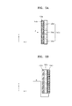
- FIG. 5A is a schematic cross-sectional view taken along a line V-V of FIG. 1 ;
- FIG. 5B shows a comparative embodiment of the secondary battery of FIG. 5A ;
- FIG. 6 shows a modification of the secondary battery of FIG. 5A ;
- FIG. 7 shows another modification of the secondary battery of FIG. 5A ;
- FIG. 8 shows another modification of the secondary battery of FIG. 5A ;
- FIG. 9 is a schematic perspective view of a secondary battery according to another embodiment of the present invention.
- FIG. 10 is a schematic cross-sectional view taken along a line X-X of FIG. 9 .
- FIG. 1 is a schematic exploded perspective view of a secondary battery 100 according to an embodiment of the present invention.
- FIG. 2 is a schematic assembled top perspective view of the secondary battery of FIG. 1 .
- FIG. 3 is a schematic assembled bottom perspective view of the secondary battery of FIG. 1 .
- FIG. 4 is a top plan view of the secondary battery of FIG. 1 .
- the secondary battery 100 may be a polymer type secondary battery.
- the polymer type secondary battery 100 may include an electrode assembly 110 , a case 120 , an electrolytic solution (not shown), and an identifying tape 150 .
- the first case 121 may have a three-layered structure including a metal foil 121 a 1 , and an internal insulating film 121 a 2 or coating layer and an external insulating film 121 a 3 or sealing layer stacked on opposite sides of the metal foil 121 a 1 .
- the structure of the first case 121 is not limited thereto and various functional layers may also be added thereto.
- the second case 122 may also have the same stack structure as the first case 121 .
- the internal insulating film 121 a 2 may be a layer that is to be thermally fused. That is, layers that are to be thermally fused are formed on sides of the first case 121 and the second case 122 that face each other.
- the internal insulating film 121 a 2 includes a polyolefin layer such as a casted polypropylene (CPP) layer.
- the CPP layer may be replaced with a material layer including a polyolefin resin selected from the group consisting of chlorinated polypropylene, polyethylene, an ethylenepropylene copolymer, a polyethylene-acrylic acid copolymer, and a polypropylene-acrylic acid copolymer.
- the metal foil 121 a 1 layer may function as a substrate for maintaining mechanical strength and a barrier layer for preventing transmission of moisture and oxygen.
- the metal foil 121 a 1 may include an aluminum (Al) layer.
- the external insulating film 121 a 3 may function as a substrate and a protective layer.
- the external insulating film 121 a 3 may include, for example, nylon.
- the first case 121 and the second case 122 may be sealed together by a sealing portion 124 .
- the sealing portion 124 may be sides of the internal insulating film 121 a 2 , which is a layer that is to be thermally fused, of each of the first case 121 and the second case 122 .
- the sealing portion 124 may be thermally fused to be sealed.
- the sealing portion 124 may cover the insulating tape 116 , which is for a positive electrode, and the insulating tape 117 , which is for a negative electrode, to seal the first case 121 and the second case 122 .
- the first case 121 and the second case 122 may be sealed by the sealing portion 124 while at least one portion of each of the positive tap 114 and the negative tap 115 protrudes out of the case 120 .
- first case 121 and the second case 122 may be initially connected to each other, and the first case 121 and the second case 122 may be sealed by the other two sides.
- three sides of each of the first case 121 and the second case 122 may be initially connected to each other, and the first case 121 and the second case 122 may be sealed by the remaining one side.
- the leaked electrolytic solution may cause safety problems and pollute an environment around the case 120 .
- the leaked electrolytic solution should be detected at an early stage of the leakage and the leakage should be managed for safety.
- the electrolytic solution may leak through the sealing portion 124 when sealing the case 120 due to defects or insulating resistance destruction. If a relatively small amount of the electrolytic solution leaks, it is difficult to immediately detect the leakage.
- the leaked electrolytic solution may deteriorate the performance of the secondary battery 100 and cause safety problems by corroding components around the secondary battery 100 .
- the identifying tape 150 may be attached to the case 120 .
- the identifying tape 150 may be attached to the case 120 to correspond to the sealing portion 124 , which seals the first case 121 and the second case 122 .
- the identifying tape 150 may have a width sufficient for covering at least a portion of the first case 121 and the second case 122 .
- the first case 121 and the second case 122 each having a quadrangular shape are initially connected to each other on one side, and the other three sides thereof are sealed by the sealing portion 124 . Accordingly, the identifying tape 150 may be disposed on the three sides.
- identifying tapes 150 , 151 , and 152 respectively corresponding to the three sides are separately shown in FIG. 1
- the identifying tapes 150 , 151 , and 152 may be connected to one another by being integrally formed.
- the positive tap 114 and the negative tap 115 may pass and protrude from between the first case 121 and the second case 122 , and the identifying tape 150 may cover at least one portion of the positive tap 114 and/or the negative tap 115 .
- an insulating tape for insulating the sealing portion 124 may be attached thereto.
- the insulating tape may be disposed to cover a side of the metal foil 121 a 1 to prevent the side of the metal foil 121 a 1 from being exposed.
- the identifying tape 150 may also function as the insulating tape. That is, the identifying tape 150 may be disposed to cover at least the side of the metal foil 121 a 1 in order to insulate the metal foil 121 a 1 when the identifying tape 150 is attached to the case 120 .
- the identifying tape 151 may have identifying tape holes 150 h corresponding to the positive tap 114 and the negative tap 115 .
- FIGS. 2 , 3 , and 4 are schematic top perspective, bottom perspective, and top plan views of the case 120 , respectively.
- a first region 150 a 1 of the identifying tape 150 may be attached to a top surface of the first case 121
- a second region 150 a 2 of the identifying tape 150 may be attached to sides of the first case 121 and the second case 122
- a third region 150 a 3 of the identifying tape 150 may be attached to a bottom surface of the second case 122 .
- the identifying tape 150 corresponds to the three sides of the sealing portion 124 , but the present embodiment is not limited thereto. In other words, the identifying tape 150 may be formed on portions of the three sides of the sealing portion 124 or the side on which the sealing portion 124 is not formed.
- FIG. 5A is a schematic cross-sectional view taken along a line V-V of FIG. 1 .
- the identifying tape 150 may include a base film 150 a , an adhesive material 150 b , and a discoloration material 150 c.
- the base film 150 a may be a transparent layer. Since the base film 150 a is transparent, a change in the discoloration material 150 c may be observed through the base film 150 a .
- the base film 150 a may be an insulating layer. Since the base film 150 a is an insulating layer, the identifying tape 150 may function as an insulating tape.
- the adhesive material 150 b may be disposed on one surface of the base film 150 a .
- the adhesive material 150 b may also be transparent.
- the discoloration material 150 c may include a material that reacts with the electrolytic solution and that discolors after it reacts with the electrolytic solution.
- the discoloration material 150 c may include a litmus pigment.
- the discoloration material 150 c may be a piece of litmus paper. Accordingly, the litmus pigment may change color due to the acidity of the leaked electrolytic solution so that a user may detect the leakage of the electrolytic solution.
- the identifying tape 150 is disposed to correspond to the sealing portion 124 to detect even a relatively small amount of the electrolytic solution since there is a high possibility that leakage of the electrolytic solution occurs at the sealing portion 124 .
- FIG. 5B A comparative embodiment of FIG. 5A will be described with reference to FIG. 5B .
- the discoloration material 50 c and the adhesive material 50 b are disposed on opposite sides of the base film 50 a .
- a pathway on which the electrolytic solution leaks is shown by an arrow B.
- the amount of the leaked electrolytic solution should be relatively great to pass the sealing portion 124 and the base film 150 a to contact the discoloration material 150 c for the reaction between the electrolytic solution and the discoloration material 150 c .
- a greater amount of the electrolytic solution is required (to leak) to detect the leakage of the electrolytic solution according to the comparative embodiment shown in FIG. 5B , when compared to the embodiment of FIG. 5A in which the discoloration occurs even when a relatively small amount of the electrolytic solution leaks.
- the comparative embodiment of FIG. 5B is not efficient.
- FIG. 6 shows a modification of the tape of FIG. 5A .
- the adhesive material 150 b and the discoloration material 150 c are disposed on one surface of the base film 150 a .
- the adhesive material 150 b may be used to form a pattern on the base film 150 a .
- layers formed of the adhesive material 150 b may be formed spaced apart from each other, and the discoloration material 150 c may fill the space between the layers formed of the adhesive material 150 b.
- FIG. 7 shows another modification of the tape of FIG. 5A .
- the adhesive material 150 b and the discoloration material 150 c are disposed on one surface of the base film 150 a .
- the discoloration material 150 c may be used to form layers with patterns on the base film 150 a .
- the layers formed of the discoloration material 150 c may be spaced apart from each other to form the patterns, and the adhesive material 150 b may fill the space between the patterns formed of the discoloration material 150 c .
- the discoloration material 150 c is formed on one surface of the base film 150 a to discolor when it contacts with the leaked electrolytic solution.
- a positive current collecting unit 40 a may be attached to a positive electrode uncoated portion of the electrode assembly 10 by welding.
- the positive current collecting unit 40 a may be electrically connected to the electrode terminal 221 , here, a positive terminal, using a lead member 228 as a medium. Accordingly, the positive electrode terminal 221 may be connected to the positive electrode 11 of the electrode assembly 10 via the lead member 228 and the positive current collecting unit 40 a .
- a negative electrode current collecting unit 40 b is electrically connected to the electrode terminal 222 , here, a negative terminal, using another lead member 228 as a medium. Accordingly, the negative electrode terminal 222 may be connected to the negative electrode 12 of the electrode assembly 10 via the lead member 228 and the negative electrode current collecting unit 40 b .
- An insulating member 226 is disposed between the lead member 228 and a case 230 .
- the electrode terminals 221 and 222 include the positive electrode terminal 221 and the negative electrode terminal 222 .
- the positive electrode terminal 221 and the negative electrode terminal 222 are respectively electrically connected to the positive electrode 11 and the negative electrode 12 of the electrode assembly 10 and are exposed outside of the cases 230 and 234 .
- the positive electrode terminal 221 or the negative electrode terminal 222 may be connected to the cases 230 and 234 .
- the cases 230 and 234 may include a first case 234 and a second case 230 .
- An identifying tape 250 may be disposed on a sealing portion that seals the first case 234 and the second case 230 .
- the first case 234 accommodates the electrode assembly 10 , and one surface of the first case 234 has an opening.
- the second case 230 may be a cap plate for closing the opening of the first case 234 to seal the electrolytic solution.
- the identifying tape 250 may be disposed to correspond to a portion for sealing the first case 234 and the second case 230 .
- the second case 230 may be disposed on one surface of the first case 234 .
- the first case 234 may have a square pillar can shape with one surface open, and the second case 230 may seal the opening of the first case 234 .
- the electrode assembly 10 and the electrolytic solution may be placed in the first case 234 via the opening of the first case 234 .
- the second case 230 may cover the first case 234 in such a way that the electrode terminals 221 and 222 protrude from the first and second case 230 and 234 .
- the boundary between the first case 234 and the second case 230 is welded by a laser beam to seal the first case 234 in which the electrode assembly 10 and the electrolytic solution are accommodated.
- the portion welded by the laser beam may be the sealing portion.
- a safety vent 239 having a groove that breaks at a predetermined internal pressure may be formed in the second case 230 .
- An identifying tape 252 may be disposed to correspond to the safety vent 239 . That is, the identifying tape 252 may be disposed to cover at least one portion of the safety vent 239 or along the shape of the safety vent 239 around the safety vent 239 .
- An identifying tape 252 may include the base film 150 a .
- the discoloration material 150 c may be disposed between the base film 150 a and the safety vent 239 .
- An identifying tape 253 may be disposed to correspond to the electrode terminals 221 and 222 penetrating the second case 230 and protruding from the second case 230 .
- the identifying tape 253 may be disposed to cover at least one portion of the electrode terminals 221 and 222 or along the shape of the electrode terminals 221 and 222 around the electrode terminals 221 and 222 .
- the discoloration material 150 c may be disposed between the base film 150 a and the electrode terminals 221 and 222 .
Landscapes
- Chemical & Material Sciences (AREA)
- Chemical Kinetics & Catalysis (AREA)
- Electrochemistry (AREA)
- General Chemical & Material Sciences (AREA)
- Engineering & Computer Science (AREA)
- Manufacturing & Machinery (AREA)
- Physics & Mathematics (AREA)
- General Physics & Mathematics (AREA)
- Condensed Matter Physics & Semiconductors (AREA)
- Dispersion Chemistry (AREA)
- Inorganic Chemistry (AREA)
- Theoretical Computer Science (AREA)
- Materials Engineering (AREA)
- Sealing Battery Cases Or Jackets (AREA)
Abstract
Description
Claims (20)
Applications Claiming Priority (2)
| Application Number | Priority Date | Filing Date | Title |
|---|---|---|---|
| KR10-2010-0127861 | 2010-12-14 | ||
| KR1020100127861A KR101213482B1 (en) | 2010-12-14 | 2010-12-14 | Secondary battery |
Publications (2)
| Publication Number | Publication Date |
|---|---|
| US20120148888A1 US20120148888A1 (en) | 2012-06-14 |
| US9034498B2 true US9034498B2 (en) | 2015-05-19 |
Family
ID=46199700
Family Applications (1)
| Application Number | Title | Priority Date | Filing Date |
|---|---|---|---|
| US13/231,858 Expired - Fee Related US9034498B2 (en) | 2010-12-14 | 2011-09-13 | Secondary battery |
Country Status (2)
| Country | Link |
|---|---|
| US (1) | US9034498B2 (en) |
| KR (1) | KR101213482B1 (en) |
Families Citing this family (18)
| Publication number | Priority date | Publication date | Assignee | Title |
|---|---|---|---|---|
| US20140015535A1 (en) * | 2012-07-12 | 2014-01-16 | Covidien Lp | Devices, systems, and methods for battery cell fault detection |
| US20140154536A1 (en) * | 2012-12-04 | 2014-06-05 | Ford Global Technologies, Llc | Methods and devices for detecting venting of a battery cell |
| KR102084100B1 (en) | 2013-08-22 | 2020-04-14 | 삼성에스디아이 주식회사 | Pouch type rechargeable battery |
| KR101519742B1 (en) * | 2013-11-28 | 2015-05-12 | 율촌화학 주식회사 | Cell pouch having anti-stress impact and stability, and preparing method thereof |
| KR101540857B1 (en) * | 2013-11-28 | 2015-07-31 | 율촌화학 주식회사 | Polymer film for lead tab of secondary battery |
| KR101770699B1 (en) * | 2015-04-15 | 2017-08-23 | 주식회사 엘지화학 | A washer for electrolyte leakage detection and a secondary battery comprising the same |
| US10573856B2 (en) * | 2015-05-14 | 2020-02-25 | GM Global Technology Operations LLC | Barrier layer coatings for battery pouch cell seal |
| CN105304834A (en) * | 2015-10-08 | 2016-02-03 | 浙江超威创元实业有限公司 | Aluminum plastic film capable of detecting battery leakage |
| KR102112670B1 (en) * | 2015-10-28 | 2020-05-19 | 주식회사 엘지화학 | Battery Cell of Venting Structure Using Taping |
| KR101958763B1 (en) * | 2016-06-27 | 2019-03-15 | 주식회사 엘지화학 | Rechargeable battery and the manufacturing method |
| KR20190076698A (en) * | 2017-12-22 | 2019-07-02 | 주식회사 엘지화학 | A washer for a secondary battery, a secondary battery comprising the washer, and method for preparing the washer |
| KR102669975B1 (en) * | 2019-02-21 | 2024-05-29 | 삼성에스디아이 주식회사 | Battery pack |
| KR102356020B1 (en) | 2019-09-30 | 2022-01-27 | 에스케이온 주식회사 | Pouch Case, Pouch Type Secondary Battery And Manufacturing Method Thereof |
| KR102395231B1 (en) * | 2019-10-24 | 2022-05-04 | 주식회사 엘지에너지솔루션 | Battery cell and battery module including the same |
| JP7425970B2 (en) * | 2020-04-27 | 2024-02-01 | Toppanホールディングス株式会社 | Terminal film for power storage devices and power storage devices |
| KR20220010384A (en) * | 2020-07-17 | 2022-01-25 | 주식회사 엘지에너지솔루션 | Button type secondary battery and manufacturing method thereof |
| KR20230115443A (en) | 2022-01-27 | 2023-08-03 | 주식회사 엘지에너지솔루션 | Color-Changing Moisture Detection Sheet, and Lithium Secondary Battery Components Comprising the Same |
| WO2024204834A1 (en) * | 2023-03-29 | 2024-10-03 | 大日本印刷株式会社 | Power storage device and protective member for power storage device |
Citations (9)
| Publication number | Priority date | Publication date | Assignee | Title |
|---|---|---|---|---|
| KR20010058677A (en) | 1999-12-30 | 2001-07-06 | 장용균 | Lithium secondary battery |
| KR20060059714A (en) | 2004-11-29 | 2006-06-02 | 삼성에스디아이 주식회사 | Lithium ion secondary battery |
| US7122276B2 (en) * | 2002-08-20 | 2006-10-17 | Samsung Sdi Co., Ltd. | Pouch type secondary battery with safety vent |
| JP2007265879A (en) | 2006-03-29 | 2007-10-11 | Nec Lamilion Energy Ltd | Film-armored electric device and electric device assembly |
| KR100778407B1 (en) | 2002-02-28 | 2007-11-27 | 삼성에스디아이 주식회사 | Secondary Battery with Indicating Paper |
| US20080292962A1 (en) | 2007-05-21 | 2008-11-27 | Dong-Woo Jung | Pouch-type secondary battery |
| US7618724B2 (en) * | 2004-04-13 | 2009-11-17 | Lg Chem, Ltd. | Electrochemical device comprising electrode lead having protection device |
| KR100927450B1 (en) | 2008-01-10 | 2009-11-19 | 삼성중공업 주식회사 | Leak check tape |
| KR20100053457A (en) | 2008-11-11 | 2010-05-20 | 주식회사 엘지화학 | Nonaqueous electrolyte lithium secondary battery |
-
2010
- 2010-12-14 KR KR1020100127861A patent/KR101213482B1/en not_active IP Right Cessation
-
2011
- 2011-09-13 US US13/231,858 patent/US9034498B2/en not_active Expired - Fee Related
Patent Citations (10)
| Publication number | Priority date | Publication date | Assignee | Title |
|---|---|---|---|---|
| KR20010058677A (en) | 1999-12-30 | 2001-07-06 | 장용균 | Lithium secondary battery |
| KR100778407B1 (en) | 2002-02-28 | 2007-11-27 | 삼성에스디아이 주식회사 | Secondary Battery with Indicating Paper |
| US7122276B2 (en) * | 2002-08-20 | 2006-10-17 | Samsung Sdi Co., Ltd. | Pouch type secondary battery with safety vent |
| US7618724B2 (en) * | 2004-04-13 | 2009-11-17 | Lg Chem, Ltd. | Electrochemical device comprising electrode lead having protection device |
| KR20060059714A (en) | 2004-11-29 | 2006-06-02 | 삼성에스디아이 주식회사 | Lithium ion secondary battery |
| JP2007265879A (en) | 2006-03-29 | 2007-10-11 | Nec Lamilion Energy Ltd | Film-armored electric device and electric device assembly |
| US20080292962A1 (en) | 2007-05-21 | 2008-11-27 | Dong-Woo Jung | Pouch-type secondary battery |
| KR100891383B1 (en) | 2007-05-21 | 2009-04-02 | 삼성에스디아이 주식회사 | Pouch type secondary battery |
| KR100927450B1 (en) | 2008-01-10 | 2009-11-19 | 삼성중공업 주식회사 | Leak check tape |
| KR20100053457A (en) | 2008-11-11 | 2010-05-20 | 주식회사 엘지화학 | Nonaqueous electrolyte lithium secondary battery |
Non-Patent Citations (3)
| Title |
|---|
| Machine Translation of Kim (KR 2001-0058677, published Jul. 2001, pp. 1-8). * |
| Machine Translation of Lee (KR Oct. 2006-0059714, published Jun. 2006, pp. 1-11). * |
| Machine Translation of Seo (KR 2003-0071264, published Feb. 2002, pp. 1-9). * |
Also Published As
| Publication number | Publication date |
|---|---|
| KR101213482B1 (en) | 2012-12-20 |
| KR20120066496A (en) | 2012-06-22 |
| US20120148888A1 (en) | 2012-06-14 |
Similar Documents
| Publication | Publication Date | Title |
|---|---|---|
| US9034498B2 (en) | Secondary battery | |
| US8986871B2 (en) | Electrode assembly and secondary battery having the same | |
| KR100973310B1 (en) | Electrode tab for secondary battery and secondary battery using the same | |
| EP2408039A1 (en) | Secondary battery and method of making a secondary battery | |
| KR100770115B1 (en) | Battery Pack | |
| KR20020077333A (en) | Lithium battery structure incorporating lithium pouch cells | |
| KR101357319B1 (en) | Pouch for secondary battery and pouch-type secondary battery comprising the same | |
| KR101097253B1 (en) | Secondary battery | |
| US8530077B2 (en) | Insulating case for secondary battery and secondary battery having the same | |
| KR20060112743A (en) | Cap assembly and lithium ion secondary battery with the same | |
| KR20120080148A (en) | Lithium polymer secondary battery | |
| CN114175368A (en) | Battery case of secondary battery and method for manufacturing exhaust part | |
| KR102449106B1 (en) | Secondary battery capable of internal and external pressure balancing | |
| KR101305242B1 (en) | Secondary Battery of Novel Structure | |
| KR102486134B1 (en) | Cylindrical-type Battery Comprising Gasket- Washer for High-effective Sealing | |
| KR20060097485A (en) | Assembly method for secondary battery | |
| KR100686857B1 (en) | Can type secondary battery and method of fabricating the same | |
| KR20030037771A (en) | Li-ion polymer battery | |
| US20230133623A1 (en) | Secondary Battery And Method For Repairing The Same | |
| KR20100032064A (en) | Pouch for secondary battery and secondary battery using the same | |
| KR20040107868A (en) | Pouched-type lithium secondary battery | |
| KR20180067178A (en) | Pouch type secondary battery | |
| KR100670516B1 (en) | Secondary battery and the same using method | |
| KR100303842B1 (en) | Li-ion polymer battery | |
| KR20140068550A (en) | Pouch for Secondary Cell, Pouch Type Secondary Cell and Device Comprising the Same Having Long-life Efficiency |
Legal Events
| Date | Code | Title | Description |
|---|---|---|---|
| AS | Assignment |
Owner name: SAMSUNG SDI CO., LTD., KOREA, REPUBLIC OF Free format text: ASSIGNMENT OF ASSIGNORS INTEREST;ASSIGNOR:YUN, YOUNG-KWANG;REEL/FRAME:027065/0017 Effective date: 20110901 |
|
| FEPP | Fee payment procedure |
Free format text: PAYOR NUMBER ASSIGNED (ORIGINAL EVENT CODE: ASPN); ENTITY STATUS OF PATENT OWNER: LARGE ENTITY Free format text: PAYER NUMBER DE-ASSIGNED (ORIGINAL EVENT CODE: RMPN); ENTITY STATUS OF PATENT OWNER: LARGE ENTITY |
|
| STCF | Information on status: patent grant |
Free format text: PATENTED CASE |
|
| FEPP | Fee payment procedure |
Free format text: PAYOR NUMBER ASSIGNED (ORIGINAL EVENT CODE: ASPN); ENTITY STATUS OF PATENT OWNER: LARGE ENTITY |
|
| FEPP | Fee payment procedure |
Free format text: MAINTENANCE FEE REMINDER MAILED (ORIGINAL EVENT CODE: REM.); ENTITY STATUS OF PATENT OWNER: LARGE ENTITY |
|
| LAPS | Lapse for failure to pay maintenance fees |
Free format text: PATENT EXPIRED FOR FAILURE TO PAY MAINTENANCE FEES (ORIGINAL EVENT CODE: EXP.); ENTITY STATUS OF PATENT OWNER: LARGE ENTITY |
|
| STCH | Information on status: patent discontinuation |
Free format text: PATENT EXPIRED DUE TO NONPAYMENT OF MAINTENANCE FEES UNDER 37 CFR 1.362 |
|
| FP | Lapsed due to failure to pay maintenance fee |
Effective date: 20190519 |