EP2408039A1 - Secondary battery and method of making a secondary battery - Google Patents
Secondary battery and method of making a secondary battery Download PDFInfo
- Publication number
- EP2408039A1 EP2408039A1 EP11166792A EP11166792A EP2408039A1 EP 2408039 A1 EP2408039 A1 EP 2408039A1 EP 11166792 A EP11166792 A EP 11166792A EP 11166792 A EP11166792 A EP 11166792A EP 2408039 A1 EP2408039 A1 EP 2408039A1
- Authority
- EP
- European Patent Office
- Prior art keywords
- bonding
- case
- secondary battery
- bonding member
- resin layer
- Prior art date
- Legal status (The legal status is an assumption and is not a legal conclusion. Google has not performed a legal analysis and makes no representation as to the accuracy of the status listed.)
- Withdrawn
Links
- 238000004519 manufacturing process Methods 0.000 title claims description 13
- 239000010410 layer Substances 0.000 claims description 96
- 229920005989 resin Polymers 0.000 claims description 52
- 239000011347 resin Substances 0.000 claims description 52
- 125000006850 spacer group Chemical group 0.000 claims description 30
- 229910052751 metal Inorganic materials 0.000 claims description 26
- 239000002184 metal Substances 0.000 claims description 26
- -1 polypropylene Polymers 0.000 claims description 18
- 238000000034 method Methods 0.000 claims description 14
- 239000004698 Polyethylene Substances 0.000 claims description 6
- 239000004743 Polypropylene Substances 0.000 claims description 6
- 239000012790 adhesive layer Substances 0.000 claims description 6
- 229920000573 polyethylene Polymers 0.000 claims description 6
- 229920001155 polypropylene Polymers 0.000 claims description 6
- 229920002239 polyacrylonitrile Polymers 0.000 claims description 4
- KKEYFWRCBNTPAC-UHFFFAOYSA-L terephthalate(2-) Chemical compound [O-]C(=O)C1=CC=C(C([O-])=O)C=C1 KKEYFWRCBNTPAC-UHFFFAOYSA-L 0.000 claims description 2
- 239000000463 material Substances 0.000 description 14
- PXHVJJICTQNCMI-UHFFFAOYSA-N Nickel Chemical compound [Ni] PXHVJJICTQNCMI-UHFFFAOYSA-N 0.000 description 10
- 239000004411 aluminium Substances 0.000 description 10
- 229910052782 aluminium Inorganic materials 0.000 description 10
- XAGFODPZIPBFFR-UHFFFAOYSA-N aluminium Chemical compound [Al] XAGFODPZIPBFFR-UHFFFAOYSA-N 0.000 description 10
- 239000003792 electrolyte Substances 0.000 description 10
- 239000007773 negative electrode material Substances 0.000 description 9
- 239000007774 positive electrode material Substances 0.000 description 9
- 230000008569 process Effects 0.000 description 9
- SECXISVLQFMRJM-UHFFFAOYSA-N N-Methylpyrrolidone Chemical compound CN1CCCC1=O SECXISVLQFMRJM-UHFFFAOYSA-N 0.000 description 8
- 238000007789 sealing Methods 0.000 description 6
- 239000011230 binding agent Substances 0.000 description 5
- 239000005025 cast polypropylene Substances 0.000 description 5
- 229910052759 nickel Inorganic materials 0.000 description 5
- OKTJSMMVPCPJKN-UHFFFAOYSA-N Carbon Chemical compound [C] OKTJSMMVPCPJKN-UHFFFAOYSA-N 0.000 description 4
- 239000004020 conductor Substances 0.000 description 4
- 239000002002 slurry Substances 0.000 description 4
- 239000002904 solvent Substances 0.000 description 4
- 238000004804 winding Methods 0.000 description 4
- 239000002033 PVDF binder Substances 0.000 description 3
- 229920006284 nylon film Polymers 0.000 description 3
- 229920002981 polyvinylidene fluoride Polymers 0.000 description 3
- 238000003825 pressing Methods 0.000 description 3
- 239000010935 stainless steel Substances 0.000 description 3
- 229910001220 stainless steel Inorganic materials 0.000 description 3
- 239000013589 supplement Substances 0.000 description 3
- 238000003466 welding Methods 0.000 description 3
- 239000004677 Nylon Substances 0.000 description 2
- 239000004952 Polyamide Substances 0.000 description 2
- FDLZQPXZHIFURF-UHFFFAOYSA-N [O-2].[Ti+4].[Li+] Chemical compound [O-2].[Ti+4].[Li+] FDLZQPXZHIFURF-UHFFFAOYSA-N 0.000 description 2
- 150000001875 compounds Chemical class 0.000 description 2
- 229920006351 engineering plastic Polymers 0.000 description 2
- 229910002804 graphite Inorganic materials 0.000 description 2
- 239000010439 graphite Substances 0.000 description 2
- 150000002500 ions Chemical class 0.000 description 2
- 229910000625 lithium cobalt oxide Inorganic materials 0.000 description 2
- BFZPBUKRYWOWDV-UHFFFAOYSA-N lithium;oxido(oxo)cobalt Chemical compound [Li+].[O-][Co]=O BFZPBUKRYWOWDV-UHFFFAOYSA-N 0.000 description 2
- 238000000465 moulding Methods 0.000 description 2
- 229920001778 nylon Polymers 0.000 description 2
- 229920003023 plastic Polymers 0.000 description 2
- 239000004033 plastic Substances 0.000 description 2
- 229920002647 polyamide Polymers 0.000 description 2
- 229920001707 polybutylene terephthalate Polymers 0.000 description 2
- 229920000515 polycarbonate Polymers 0.000 description 2
- 239000004417 polycarbonate Substances 0.000 description 2
- 229920000139 polyethylene terephthalate Polymers 0.000 description 2
- 239000005020 polyethylene terephthalate Substances 0.000 description 2
- 229920000642 polymer Polymers 0.000 description 2
- RYGMFSIKBFXOCR-UHFFFAOYSA-N Copper Chemical compound [Cu] RYGMFSIKBFXOCR-UHFFFAOYSA-N 0.000 description 1
- WHXSMMKQMYFTQS-UHFFFAOYSA-N Lithium Chemical compound [Li] WHXSMMKQMYFTQS-UHFFFAOYSA-N 0.000 description 1
- RTAQQCXQSZGOHL-UHFFFAOYSA-N Titanium Chemical compound [Ti] RTAQQCXQSZGOHL-UHFFFAOYSA-N 0.000 description 1
- 239000006230 acetylene black Substances 0.000 description 1
- 239000004840 adhesive resin Substances 0.000 description 1
- 229920006223 adhesive resin Polymers 0.000 description 1
- 230000008901 benefit Effects 0.000 description 1
- 238000001354 calcination Methods 0.000 description 1
- 229910052799 carbon Inorganic materials 0.000 description 1
- 230000008859 change Effects 0.000 description 1
- 239000012141 concentrate Substances 0.000 description 1
- 229910052802 copper Inorganic materials 0.000 description 1
- 239000010949 copper Substances 0.000 description 1
- 239000010408 film Substances 0.000 description 1
- 238000010438 heat treatment Methods 0.000 description 1
- 229910052744 lithium Inorganic materials 0.000 description 1
- 238000012986 modification Methods 0.000 description 1
- 230000004048 modification Effects 0.000 description 1
- 239000004745 nonwoven fabric Substances 0.000 description 1
- 239000012466 permeate Substances 0.000 description 1
- 239000000126 substance Substances 0.000 description 1
- 229920003002 synthetic resin Polymers 0.000 description 1
- 239000000057 synthetic resin Substances 0.000 description 1
- 239000010409 thin film Substances 0.000 description 1
- XOLBLPGZBRYERU-UHFFFAOYSA-N tin dioxide Chemical compound O=[Sn]=O XOLBLPGZBRYERU-UHFFFAOYSA-N 0.000 description 1
- 229910001887 tin oxide Inorganic materials 0.000 description 1
- 239000010936 titanium Substances 0.000 description 1
- 229910052719 titanium Inorganic materials 0.000 description 1
- 238000002834 transmittance Methods 0.000 description 1
Images


Classifications
-
- H—ELECTRICITY
- H01—ELECTRIC ELEMENTS
- H01M—PROCESSES OR MEANS, e.g. BATTERIES, FOR THE DIRECT CONVERSION OF CHEMICAL ENERGY INTO ELECTRICAL ENERGY
- H01M50/00—Constructional details or processes of manufacture of the non-active parts of electrochemical cells other than fuel cells, e.g. hybrid cells
- H01M50/10—Primary casings; Jackets or wrappings
- H01M50/102—Primary casings; Jackets or wrappings characterised by their shape or physical structure
- H01M50/105—Pouches or flexible bags
-
- H—ELECTRICITY
- H01—ELECTRIC ELEMENTS
- H01M—PROCESSES OR MEANS, e.g. BATTERIES, FOR THE DIRECT CONVERSION OF CHEMICAL ENERGY INTO ELECTRICAL ENERGY
- H01M50/00—Constructional details or processes of manufacture of the non-active parts of electrochemical cells other than fuel cells, e.g. hybrid cells
- H01M50/10—Primary casings; Jackets or wrappings
- H01M50/147—Lids or covers
- H01M50/148—Lids or covers characterised by their shape
-
- H—ELECTRICITY
- H01—ELECTRIC ELEMENTS
- H01M—PROCESSES OR MEANS, e.g. BATTERIES, FOR THE DIRECT CONVERSION OF CHEMICAL ENERGY INTO ELECTRICAL ENERGY
- H01M10/00—Secondary cells; Manufacture thereof
- H01M10/02—Details
-
- H—ELECTRICITY
- H01—ELECTRIC ELEMENTS
- H01M—PROCESSES OR MEANS, e.g. BATTERIES, FOR THE DIRECT CONVERSION OF CHEMICAL ENERGY INTO ELECTRICAL ENERGY
- H01M50/00—Constructional details or processes of manufacture of the non-active parts of electrochemical cells other than fuel cells, e.g. hybrid cells
- H01M50/10—Primary casings; Jackets or wrappings
- H01M50/116—Primary casings; Jackets or wrappings characterised by the material
- H01M50/117—Inorganic material
- H01M50/119—Metals
-
- H—ELECTRICITY
- H01—ELECTRIC ELEMENTS
- H01M—PROCESSES OR MEANS, e.g. BATTERIES, FOR THE DIRECT CONVERSION OF CHEMICAL ENERGY INTO ELECTRICAL ENERGY
- H01M50/00—Constructional details or processes of manufacture of the non-active parts of electrochemical cells other than fuel cells, e.g. hybrid cells
- H01M50/10—Primary casings; Jackets or wrappings
- H01M50/116—Primary casings; Jackets or wrappings characterised by the material
- H01M50/121—Organic material
-
- H—ELECTRICITY
- H01—ELECTRIC ELEMENTS
- H01M—PROCESSES OR MEANS, e.g. BATTERIES, FOR THE DIRECT CONVERSION OF CHEMICAL ENERGY INTO ELECTRICAL ENERGY
- H01M50/00—Constructional details or processes of manufacture of the non-active parts of electrochemical cells other than fuel cells, e.g. hybrid cells
- H01M50/10—Primary casings; Jackets or wrappings
- H01M50/116—Primary casings; Jackets or wrappings characterised by the material
- H01M50/124—Primary casings; Jackets or wrappings characterised by the material having a layered structure
- H01M50/126—Primary casings; Jackets or wrappings characterised by the material having a layered structure comprising three or more layers
- H01M50/129—Primary casings; Jackets or wrappings characterised by the material having a layered structure comprising three or more layers with two or more layers of only organic material
-
- H—ELECTRICITY
- H01—ELECTRIC ELEMENTS
- H01M—PROCESSES OR MEANS, e.g. BATTERIES, FOR THE DIRECT CONVERSION OF CHEMICAL ENERGY INTO ELECTRICAL ENERGY
- H01M50/00—Constructional details or processes of manufacture of the non-active parts of electrochemical cells other than fuel cells, e.g. hybrid cells
- H01M50/10—Primary casings; Jackets or wrappings
- H01M50/131—Primary casings; Jackets or wrappings characterised by physical properties, e.g. gas permeability, size or heat resistance
- H01M50/133—Thickness
-
- H—ELECTRICITY
- H01—ELECTRIC ELEMENTS
- H01M—PROCESSES OR MEANS, e.g. BATTERIES, FOR THE DIRECT CONVERSION OF CHEMICAL ENERGY INTO ELECTRICAL ENERGY
- H01M50/00—Constructional details or processes of manufacture of the non-active parts of electrochemical cells other than fuel cells, e.g. hybrid cells
- H01M50/10—Primary casings; Jackets or wrappings
- H01M50/147—Lids or covers
- H01M50/155—Lids or covers characterised by the material
- H01M50/157—Inorganic material
- H01M50/159—Metals
-
- H—ELECTRICITY
- H01—ELECTRIC ELEMENTS
- H01M—PROCESSES OR MEANS, e.g. BATTERIES, FOR THE DIRECT CONVERSION OF CHEMICAL ENERGY INTO ELECTRICAL ENERGY
- H01M50/00—Constructional details or processes of manufacture of the non-active parts of electrochemical cells other than fuel cells, e.g. hybrid cells
- H01M50/10—Primary casings; Jackets or wrappings
- H01M50/147—Lids or covers
- H01M50/155—Lids or covers characterised by the material
- H01M50/16—Organic material
-
- H—ELECTRICITY
- H01—ELECTRIC ELEMENTS
- H01M—PROCESSES OR MEANS, e.g. BATTERIES, FOR THE DIRECT CONVERSION OF CHEMICAL ENERGY INTO ELECTRICAL ENERGY
- H01M50/00—Constructional details or processes of manufacture of the non-active parts of electrochemical cells other than fuel cells, e.g. hybrid cells
- H01M50/10—Primary casings; Jackets or wrappings
- H01M50/147—Lids or covers
- H01M50/155—Lids or covers characterised by the material
- H01M50/164—Lids or covers characterised by the material having a layered structure
-
- H—ELECTRICITY
- H01—ELECTRIC ELEMENTS
- H01M—PROCESSES OR MEANS, e.g. BATTERIES, FOR THE DIRECT CONVERSION OF CHEMICAL ENERGY INTO ELECTRICAL ENERGY
- H01M50/00—Constructional details or processes of manufacture of the non-active parts of electrochemical cells other than fuel cells, e.g. hybrid cells
- H01M50/10—Primary casings; Jackets or wrappings
- H01M50/172—Arrangements of electric connectors penetrating the casing
- H01M50/174—Arrangements of electric connectors penetrating the casing adapted for the shape of the cells
- H01M50/178—Arrangements of electric connectors penetrating the casing adapted for the shape of the cells for pouch or flexible bag cells
-
- H—ELECTRICITY
- H01—ELECTRIC ELEMENTS
- H01M—PROCESSES OR MEANS, e.g. BATTERIES, FOR THE DIRECT CONVERSION OF CHEMICAL ENERGY INTO ELECTRICAL ENERGY
- H01M50/00—Constructional details or processes of manufacture of the non-active parts of electrochemical cells other than fuel cells, e.g. hybrid cells
- H01M50/50—Current conducting connections for cells or batteries
- H01M50/543—Terminals
- H01M50/547—Terminals characterised by the disposition of the terminals on the cells
- H01M50/55—Terminals characterised by the disposition of the terminals on the cells on the same side of the cell
-
- H—ELECTRICITY
- H01—ELECTRIC ELEMENTS
- H01M—PROCESSES OR MEANS, e.g. BATTERIES, FOR THE DIRECT CONVERSION OF CHEMICAL ENERGY INTO ELECTRICAL ENERGY
- H01M50/00—Constructional details or processes of manufacture of the non-active parts of electrochemical cells other than fuel cells, e.g. hybrid cells
- H01M50/50—Current conducting connections for cells or batteries
- H01M50/543—Terminals
- H01M50/552—Terminals characterised by their shape
- H01M50/553—Terminals adapted for prismatic, pouch or rectangular cells
-
- Y—GENERAL TAGGING OF NEW TECHNOLOGICAL DEVELOPMENTS; GENERAL TAGGING OF CROSS-SECTIONAL TECHNOLOGIES SPANNING OVER SEVERAL SECTIONS OF THE IPC; TECHNICAL SUBJECTS COVERED BY FORMER USPC CROSS-REFERENCE ART COLLECTIONS [XRACs] AND DIGESTS
- Y02—TECHNOLOGIES OR APPLICATIONS FOR MITIGATION OR ADAPTATION AGAINST CLIMATE CHANGE
- Y02E—REDUCTION OF GREENHOUSE GAS [GHG] EMISSIONS, RELATED TO ENERGY GENERATION, TRANSMISSION OR DISTRIBUTION
- Y02E60/00—Enabling technologies; Technologies with a potential or indirect contribution to GHG emissions mitigation
- Y02E60/10—Energy storage using batteries
Definitions
- the invention relates to a secondary battery including an electrode assembly and a pouch-type case, and a method of making the secondary battery.
- an insulating tape is attached to an electrode tab of an electrode assembly to prevent a short-circuit with a pouch-type case.
- the insulating tape attached to the electrode tab may cause leakage of electrolyte by preventing the sealing of the case.
- Embodiments of the invention aim to provide a secondary battery that prevents a short-circuit between an electrode tab and a pouch-type case without using an insulating tape for the electrode tab. Further, the embodiments aim to provide a secondary battery that can prevent leakage of electrolyte.
- the embodiments aim to allow manufacture of a secondary battery having large capacity by variously changing the thickness of an electrode assembly disposed in a pouch-type case.
- a pouch-type secondary battery comprising an electrode assembly having electrode tabs, a case accommodating the electrode assembly, wherein the tabs extend outside the case, the case comprising a housing and a cover and a bonding member disposed around a periphery of the housing for bonding the cover to the housing.
- the electrode tabs may directly contact the bonding member. Insulating tape that may be wound around the electrode tabs in a conventional pouch-type battery to insulate the electrode tabs from the pouch is therefore not required.
- the housing may comprise a flange portion and the bonding member may be formed on the flange portion.
- the battery may be sealed by thermally bonding the cover, the bonding member and the housing together.
- the housing may comprise an inner resin layer, an outer resin layer and a metal layer sandwiched between the inner resin layer and the outer resin layer, wherein the bonding member is formed on the inner resin layer.
- the inner resin layer may include an adhesive layer.
- the bonding member may comprise one or more bonding layers.
- the bonding member may have a thickness between 100 ⁇ m and 200 ⁇ m.
- the bonding member may comprise one or more of polypropylene, polyethylene, polyethelyne terephthalate or polyacrylonitrile.
- the case may comprise a spacer and first and second bonding members on either side of the spacer, wherein the cover is bonded to the first bonding member.
- the secondary battery may further comprise an inner resin layer, an outer resin layer and a metal layer between the inner and outer resin layers, wherein the second bonding member is disposed between the spacer and the inner resin layer.
- the inner resin layer, the metal layer and the outer resin layer may extend to form the cover.
- the spacer may comprise grooves for receiving the electrode tabs, and the first bonding member may be arranged on top of the electrode tabs when the tabs are located in the grooves.
- a method of making a secondary battery comprising providing a case for an electrode assembly having electrode tabs, the case having a cover, disposing a bonding member on a bonding portion of the case, placing the electrode assembly in the case so that electrode tabs extend out of the case and thermally bonding the cover, the bonding member and the bonding portion of the case together.
- the method may further comprise locating the electrode tabs in grooves in a side of the case prior to disposing the bonding member on the bonding portion of the case.
- An insulating tape is not attached to the electrode tabs of the electrode assembly of the secondary battery according to the present invention. Therefore, it is possible to reduce the manufacturing cost, because an insulating tape and a process of attaching the insulating tape are not needed in the secondary battery.
- the secondary battery according to the present invention is a pouch-type secondary battery, in which there is no insulating tape where the case of the secondary battery is bonded. Therefore, it is possible to prevent leakage of electrolyte by improving the bonding ability of the case of the secondary battery.
- the housing portion for the electrode assembly in the case may be formed by the bonding members including a spacer. Therefore, it is possible to reduce the cost for the process, because the process of deep drawing for forming the housing portion in the case is not needed. Further, the size of the housing portion of the electrode assembly is not limited by deep drawing. Accordingly, it is possible to variously change the thickness of the electrode assembly, and particularly, it is advantageous in manufacturing a secondary battery having high capacity.
- a pouch-type secondary battery 100 includes an electrode assembly 10, a pouch-type case 110 accommodating the electrode assembly 10, and a bonding member 150 for sealing the pouch-type case 110.
- the case 110 has a bonding portion 140 where the bonding member 150 for sealing the case 110 is disposed.
- the electrode assembly 10 is formed by winding a first electrode plate, a second electrode plate, and a separator interposed between the electrode plates.
- a first electrode tab 20 is attached to the first electrode plate and a second electrode tab 30 is attached to the second electrode.
- the electrode assembly 10 is electrically connected with the outside by the first and second electrode tabs 20, 30 attached to the electrode plates.
- the first electrode plate is referred to as a negative plate and the second electrode plate is referred to as a positive plate, for the convenience of description.
- the negative plate includes a negative active material layer and an uncoated part.
- the negative active material layer is a portion coated with a negative active material on both sides or one side of a negative collector and the uncoated part is a portion without the negative active material coated in the negative collector.
- the negative current collector is a material having high conductivity and is not specifically limited as long as it does not cause chemical changes.
- the negative current collector may be made of aluminium, nickel, titanium, and calcination carbon.
- the negative active material layer includes a negative active material, which is a layered compound containing lithium, a conductive material improving conductivity, and a binder improving bonding force between the layered compound and the conductive material.
- the negative active material layer is formed by mixing the negative active material, the conductive material, and the binder with a solvent in a slurry and then applying the slurry to the negative collector.
- the solvent may be NMP (N-Methyl-2-Pyrrolidone)
- the negative active material may be lithium cobalt oxide (LiCoO 2 )
- the conductive material may be acetylene black
- the binder may be polyvinylidene fluoride, but they are not limited thereto.
- the positive plate includes a positive active material layer and an uncoated part.
- the positive active material layer is coated with a positive active material on both sides or one side of a positive current collector.
- the positive current collector is a conductive metal plate, and for example, may be made of copper, stainless steel, aluminium, and nickel.
- the positive active material layer is formed by mixing the positive active material and a binder improving bonding force of the positive active material with a solvent in a slurry and then applying the slurry to the positive collector.
- the solvent may be NMP (N-Methyl-2-Pyrrolidone)
- the positive active material may be graphite
- the binder may be polyvinylidene fluoride, but they are not limited thereto.
- the negative plate corresponding to the positive plate may have a smaller area than the positive plate.
- tin oxide (SnO) or lithium titanium oxide (ITO) is used for the positive active material, the negative plate corresponding to the positive plate may have a larger area than the positive plate.
- the separator is interposed between the negative plate and the positive plate.
- the separator functions as an ion path and prevents contact between the negative plate and the positive plate. Therefore, the separator is formed of an insulating thin film having high ion transmittance and mechanical strength.
- the separator may be porous film or non-woven fabric including polyethylene, polypropylene, or polyvinylidene fluoride.
- the electrode assembly 10 is formed by winding the negative plate and the positive plate with the separator interposed therebetween.
- the electrode assembly 10 wound as described above is accommodated with electrolyte in the pouch case 110 and the pouch case 110 is sealed, thereby forming the secondary battery 100.
- the electrode assembly 10 includes a first electrode tab 20 and a second electrode tab 30.
- the electrode tabs 20, 30 are attached to the uncoated parts of the negative plate and the positive plate, respectively.
- the first and second electrode tabs 20, 30 may be made of nickel or aluminium.
- the electrode tabs 20, 30 are attached to the electrode plates by any one or more of ultrasonic welding, resistance welding, and laser welding.
- the first and second electrode tabs 20, 30 are exposed to the outside of the case 110 through the bonding portion 140 of the pouch-type case 110. Therefore, the electrode assembly 10 is electrically connected with the outside by the first and second electrode tabs 20, 30 attached to the electrode plates.
- the pouch-type case 110 accommodating the electrode assembly 10 is composed of a cover 120 and a main body 130.
- the main body 130 of the pouch-type case 110 has a housing portion 130a that is a space for accommodating the electrode assembly 10 and the bonding portion 140 extending outside from the inlet of the housing portion 130a.
- the housing portion 130a may be formed by deep-drawing an integral rectangular laminate sheet.
- the cover 120 is integrally connected with one side of the bonding portion 140.
- the secondary battery 100 is manufactured by disposing the electrode assembly 10 in the housing portion 130a of the main body 130 and then thermal-bonding the bonding portion 140, with the main body 130 and the cover 120 in close contact.
- the laminate sheet of the pouch-type case 110 includes an inner resin layer, a metal layer, and an outer resin layer.
- the metal layer is a thin aluminium layer and the upper and lower sides of the thin aluminium layer are covered with synthetic resin, such as polypropylene or polyethylene.
- the laminate sheet has a stacked structure including the metal layer, the inner resin layer, and the outer resin layer.
- the inner resin layer is made of a heat adhesive resin to seal the case 110. Therefore, the case is sealed by pressing the inner resin layer, particularly heating and pressing the bonding portion.
- an insulating tape is attached to the electrode tabs of the pouch-type secondary battery.
- an insulating tape is not attached to the electrode tabs 20, 30 in the electrode assembly 10 of the secondary battery according to the present invention.
- the insulating tape is provided to prevent contact and short-circuit between the metal layer of the laminate sheet and the electrode tabs 20, 30, when sealing the pouch-type case 110.
- the insulating tape interferes with bonding of the bonding portion 140 and the cover 120 of the pouch-type case 110. Therefore, bonding of the pouch-type case 110 may be incompletely made by the insulating tape, such that a path through which moisture permeates from the outside or the electrolyte leaks from the inside to the outside may be formed.
- this is described in detail.
- the pouch-type case 110 is sealed by thermal bonding, after accommodating the electrode assembly 10 and the electrolyte therein.
- the bonding portion 140 of the pouch-type case 110 and the cover 120 contacting the bonding portion 140 are pressed by a specific jig and heated above predetermined temperature.
- the electrode tabs 20, 30 exposed to the outside through the bonding portion 140 interfere with controlling temperature and pressure required for the thermal bonding of the case 110.
- non-uniform pressure is applied by the thickness of electrode tabs 20, 30 and the insulating tapes attached to the electrode tabs 20, 30. That is, higher temperature and pressure than the thermal bonding are applied to the portions where the electrode tabs 20, 30 are positioned, in the bonding portion 140.
- the insulating tapes attached to the electrode tabs 20, 30 are easily damaged.
- a short-circuit may be caused by contact between the electrode tabs 20, 30 and the metal layer of the pouch-type case 110.
- the insulating tapes are more damaged, when the electrode tabs 20, 30 are not made of the same kind of metal as the metal layer.
- secondary batteries according to the present invention make it possible to improve sealability of the pouch-type case 110 without a short-circuit between the electrode tabs and the case, even without using an insulating tape.
- an insulating tape is not attached to the first and second electrode tabs 20, 30 of the secondary battery 100 according to the present embodiment.
- the case 110 of the secondary battery 100 according to the present embodiment further includes a separate bonding member 150 in the housing portion 130a and the bonding portion 140. The bonding member 150 is only formed the bonding portion that is bonded.
- the case 110 is composed of the inner resin layer 110a, the metal layer 110b, and the outer resin layer 110c.
- the inner resin layer 110a is a layer that is thermal-bonded by heat and pressure applied with the electrode assembly 10 accommodated, and usually made of CPP (cast polypropylene). Further, the inner resin layer 110a may further include an adhesive layer. The adhesive layer supplements small bonding force of the inner resin layer 110 to the metal layer 110b.
- the metal layer is a layer preventing air, moisture etc. from flowing into the battery and usually made of aluminium.
- the outer resin layer protects the battery from the outside, such that it needs high tensile strength and weatherability to the thickness. For example, stretched nylon film may be used for the outer resin layer.
- the bonding member 150 is separately formed and disposed on the inner resin layer 110a, which is the upper surface of the bonding portion 140 of the case 110. That is, the separate bonding member 150 is disposed on the upper surface of the bonding portion 140. Accordingly, the bonding portion 140 that is bonded in the case 110 has a thickness different from the other portions of the case. That is, since the separate bonding member 150 is disposed only on the bonding portion 140, the bonding portion 140 of the case 110 increases in thickness as much as the thickness of the bonding member 150.
- the bonding member 150 may be selectively made of any one or more of polypropylene, polyethylene, polyterephthalate, and polyacrylonitrile.
- the thickness of the bonding member 150 may be 100 ⁇ m to 200 ⁇ m.
- the bonding member 150 is likely to be damaged in the bonding or thermal bonding, when the thickness of the bonding member 150 is smaller than 100 ⁇ m. Therefore, there may be a problem that current flows through the damaged portion of the bonding portion. Further, it may be difficult to seal the case 110, when the thickness of the bonding member 150 is larger than 200 ⁇ m.
- the secondary battery 110 when the secondary battery 110 is manufactured with the pouch-type case 110 including the bonding member 150, a short-circuit does not occur even without attaching an insulating tape to the first and second electrode tabs 20, 30 of the electrode assembly 10. As shown in the figures, the first and second electrodes 20, 30 of the electrode assembly 10 are exposed to the outside through the bonding portion 140 of the case 110. The case 110 is bonded by pressing the bonding portion 140 at high temperature.
- the secondary battery 110 In the thermal bonding, the secondary battery 110 according to the present embodiment, a short-circuit with the case 110 does not occurred even though an insulating tape is not attached to the electrode tabs 20, 30. Further, since the bonding portion 140 of the case 110 is uniformly bonded by the bonding member 150, sealability of the case 110 is improved. As described above, the bonding member 150 is manufactured separately from the pouch-type case 110 and attached to the bonding portion 140.
- a pouch-type secondary battery 200 includes an electrode assembly 10, a pouch-type case 210 accommodating the electrode assembly 10, and bonding members 250 composed of a plurality of layers to seal the pouch-type case 210.
- the case 210 has a bonding portion 240 where the bonding members 250 are disposed.
- the electrode assembly 10 is formed by winding an negative plate, a positive plate, and a separator interposed between the electrode plates.
- a first electrode tab 20 is attached to the negative plate and a second electrode plate 30 is attached to the positive plate.
- the electrode assembly 10 is electrically connected with the outside by the first and second electrode tabs 20, 30 attached to the electrode plates. As described above, an insulating tape is not attached to the electrode tabs 20, 30.
- the configuration and operation of the electrode assembly 10 of the secondary battery 200 according to the present embodiment are the same as those of the electrode assembly 10 shown in FIGS. 1 to 3 , and the detailed description is not provided.
- the pouch-type case 210 accommodating the electrode assembly 10 is composed of a cover 220 and a main body 230.
- the main body 230 of the pouch-type case 210 has a housing portion 230a that is a space for accommodating the electrode assembly 10 and the bonding portion 240 extending outside from the inlet of the housing portion 230a.
- the housing portion 230a may be formed by deep-drawing an integral rectangular laminate sheet.
- the cover 220 is integrally connected with one side of the bonding portion 240.
- the secondary battery 200 is manufactured by disposing the electrode assembly in the housing portion 230a of the main body 230 and then thermal-bonding the bonding portion 240 where the bonding members 250 are disposed, with the main body 230 and the cover 120 in close contact.
- the case 210 is composed of the outer resin layer 210a, the metal layer 210b, and the inner resin layer 210c.
- the inner resin layer 210a is usually made of CPP, but may further include an adhesive layer to supplement bonding force.
- the metal layer 210b is generally made of aluminium and the outer resin layer 210c may be made of stretched nylon film.
- the configuration of the case 210 is the same as that the case 110 shown in FIGS. 1 to 3 , and the detailed description is not provided.
- the case 210 of the secondary battery 200 includes the bonding member 250 composed of a plurality of layers, which is separately manufactured.
- the bonding members 250 are disposed on the upper surface of the bonding portion 240 of the case 210. Further, the bonding members 250 are separately manufactured and disposed on the bonding portion 240, as shown in FIG. 5 . Accordingly, the bonding portion 240 of the case 210 increases in thickness as much as the thickness of the bonding members 250 and the thickness is different from the other portions without the bonding members 250.
- FIG. 6 is a view enlarging the bonding portion 240 and the bonding members 250 disposed on the upper surface of the bonding portion 240.
- the bonding member 250 is composed of a plurality of layers in the present embodiment.
- the bonding members 250 may be divided into first, second, and third bonding members 250a, 250b, 250c.
- the second boding member 250b is disposed between the first and third bonding members 250a, 250c.
- the second bonding member 250b may be made of the same material as the inner resin layer 210a of the case 210, but is not limited thereto.
- the second bonding member 250b may be made of various polymers, in accordance with the design of the secondary battery.
- the second bonding member 250b may be made of CPP.
- the first bonding member 250a is a portion that contacts the first and second electrode tabs 20, 30.
- the first and second electrode tabs 20, 30 are exposed to the outside through the first bonding member 250a.
- the bonding portion 240 is sealed substantially by the first bonding member 250a, when the cover 220 and the main body 230 of the case 210 is thermal-bonded.
- the thickness of the first bonding member 250a may be 100 ⁇ m to 200 ⁇ m.
- the first bonding member 250a is likely to be damaged in the bonding or thermal bonding, when the thickness of the first bonding member 250a is smaller than 100 ⁇ m. Further, it may be difficult to seal the case 210, when the thickness of the first bonding member 250a is larger than 200 ⁇ m.
- the third bonding portion 250c is a portion that directly contacts the bonding portion 240 of the case 210.
- the third bonding member 250c may be made of the same material as the second bonding member 250b described above. Further, the third bonding member 250c may be made of the same material as the first bonding member 250a. The interface between the second bonding member 250b and the third bonding member 250c is removed, when the third bonding member 250c and the second bonding member 250b are made of the same material. Therefore, the bonding member 250 becomes composed of only two layers.
- the third bonding member 250c and the first bonding member 250a are made of the same material, it does not need to discriminate the portion contacting the cover 220 of the case or the portion contacting the main body 230 in the bonding members 250. That is, the upper surface and the lower surface of the bonding members 250 is not discriminated. Therefore, it does not need to distinguish the direction of the bonding member 250 and the process efficiency is increased, when the bonding members 250 are separately manufactured and attached to the case 210.
- the bonding members 250 of the secondary battery 210 according to the present embodiment are shown to be composed of three layers, but as described above, the layers of the bonding member 250 may be less than three. Further, the layers of the bonding members 250 may be more than three. This depends on the kinds of materials of the layers of the bonding members 250.
- the bonding members 250 composed of a plurality of layers are disposed in the bonding portion 240 of the pouch-type case 210 according to the present embodiment. Therefore, the thickness of the bonding member 250 is added to the bonding portion 240 and the depth of the housing portion 230a of the main body 230 correspondingly increases.
- the housing portion 230a of the main body 230 is a space accommodating the electrode assembly 10.
- the depth of the housing portion 230a depends on the thickness of the electrode assembly 10.
- the housing portion 230a may be formed by deep drawing.
- the deep drawing is a method of manufacturing a container without a joint from a flat plate. A circular cylinder, a polygonal cylinder, and other complicated shapes can be achieved by the method.
- the resin layer of the laminate has small durability than the metal layer. Therefore, the depth of the housing portion 230a which can be achieved by deep drawing is limited by the resin layer.
- the depth of the housing portion 230a is increased by the bonding members 250 composed of a plurality of layers. That is, the thickness of the bonding portion 240 with the bonding members 250 is relatively increased as much as the thickness of the bonding members 250, by the thickness of the bonding members 250 themselves, which are composed of a plurality of layers. Accordingly, the housing portion 230a can generally accommodate the electrode assembly 10 having a thickness as much as the depth, which can be achieved by deep drawing, added with the thickness of the bonding members 250.
- a pouch-type secondary battery 300 includes an electrode assembly 10 and a pouch-type case 310 accommodating the electrode assembly 10, the pouch type case comprising a sidewall structure 350, the sidewall structure comprising a spacer 351 between first and second bonding members 350a, 350b.
- the case 310 has a bonding portion 340 where the second bonding member 350b for sealing the case 310 is disposed.
- the electrode assembly 10 is formed by winding a negative plate, a positive plate, and a separator interposed between the electrode plates.
- a first electrode tab 20 is attached to the negative plate and a second electrode plate 30 is attached to the positive plate.
- an insulating tape is not attached to the electrode tabs 20, 30.
- the electrode assembly 10 of the secondary battery 300 according to the present embodiment is the same as the electrode assembly 10 shown in FIGS. 1 to 3 , and the detailed description is not provided.
- the cover 320 is integrally connected with one side of the main body of the pouch-type case 310 accommodating the electrode assembly 10.
- the main body forms a base portion of the case, or can be seen as one part of a one-piece cover on which the sidewall structure is disposed, with the cover 320 extending from the base portion being folded over the sidewall structure 350 to form the case 310.
- the case 310 according to the present embodiment does not undergo deep drawing.
- the spacer 351 and bonding members 350a, b are separately manufactured and provided in the case 310.
- the case 310 is composed of the outer resin layer 310a, the metal layer 210b, and the inner resin layer 210c.
- the inner resin layer 310a is usually made of CPP and may further include an adhesive layer to supplement bonding force.
- the metal layer 310b is generally made of aluminium and the outer resin layer 310c may be made of stretched nylon film.
- a housing portion 330a accommodating the electrode assembly 10 is formed by the sidewall structure 350.
- the sidewall structure 350 having a predetermined thickness is disposed on the upper surface of the bonding portion 340 of the case 310. Therefore, the case 310 has a housing portion 330a that can accommodate the electrode assembly 10.
- the thickness of the housing portion 330a formed as described above depends on the thickness of the sidewall structure 350 disposed on the bonding portion 340.
- the case 310 does not undergo deep drawing, unlike the embodiments described above. Accordingly, since deep drawing is not performed, it is possible to reduce the manufacturing cost of the secondary battery 300. Further, the depth of the housing portion which can be achieved by deep drawing was limited. However, since the housing portion 330a of the case 310 is not formed by deep drawing in the secondary battery 300 according to the present embodiment, the depth of the housing 330a is not limited. It is therefore possible to accommodate the electrode assembly 10 having various thicknesses. Therefore, it has the advantage of manufacturing a secondary battery for accommodating a thick electrode assembly 10, that is, high capacity.
- the configuration of the case 310 is the same as that the case 310 shown in FIGS. 1 to 3 , and the detailed description is not provided.
- the space accommodating the electrode assembly 10 inside the case 310 is formed by the sidewall structure 350, which is now described in detail.
- the sidewall structure 350 is disposed on the upper surface of the bonding portion 340 of the case 310. Further, the components of the sidewall structure 350 are separately manufactured and disposed on the bonding portion 340.
- FIG. 9 is a view enlarging the bonding portion 340 and the sidewall structure 350 disposed on the upper surface of the bonding portion 340.
- the sidewall structure 350 includes the spacer 351. That is, the bonding members 350 are composed of first and second bonding members 350a, 350b, and the spacer 351 disposed between the first and second bonding members 350a, 350b.
- the first bonding member 350a is a portion that contacts the first and second electrode tabs 20, 30.
- the first and second electrode tabs 20, 30 are exposed to the outside through the first bonding member 350a.
- the first bonding member 350a is a portion that is substantially thermal-bonded with the cover 320 of the case 310.
- the first bonding member 350a may be selectively made of any one or more of polypropylene, polyethylene, polyterephthalate, and polyacrylonitrile. Further, it is preferable that the thickness of the first bonding member 350a may be 100 ⁇ m to 200 ⁇ m. The first bonding member 350a is likely to be damaged in the bonding or thermal bonding, when the thickness of the first bonding member 350a is smaller than 100 ⁇ m. Further, the electrolyte may leak due to incomplete sealing of the case 310, when the thickness of the first bonding member 350a is larger than 200 ⁇ m.
- the second bonding member 350b is a portion contacting the inner resin layer 310a of the case 310.
- the interface between the second bonding member 350b and the inner resin layer is unclear, when the second bonding member 350b is made of the same material as the inner resin layer 310a of the case 310.
- the second bonding member 350b may be made of the same material as the first bonding member 350a described above. In this case, it is advantageous to attach the bonding members 350a, b separately manufactured to the case 310. That is, since it does not need to distinguish the upper surface from the lower surface of the bonding members 350, it is possible to reduce errors caused in the related process.
- the bonding members 350a, b it is possible to simplify the process, when attaching the bonding members 350a, b to the case 310. That is, it is possible to dispose the bonding members 350a, b between the cover 320 and the main body of the case and then attach at one time the cover 320, the bonding members 350a, b, and the main body, without separately attaching the bonding members 350 to the case 310 and then attaching the cover 320 to the bonding member 350. Further, it is possible to reduce the manufacturing cost, because there is no need to add a process of attaching the bonding members 350 to the case 310.
- the material of the second bonding member 350b described above is an example and may be various polymers.
- the upper surface of the spacer 351 is covered with the first bonding member 350a and the lower surface is covered with the second bonding member 350b.
- the spacer 351 should not react with the electrolyte such that the electrode assembly 10 is not influenced by external pressure. Therefore, the spacer 351 should have high mechanical strength and anticorrosion.
- the spacer 351 may be formed by molding metal having high strength and good forming performance, or engineering plastic.
- the metal may be aluminium, stainless steel, and nickel, and the plastic may be polycarbonate, nylon, polyamide, polybutylene terephthalate, and polyethylene terephthalate.
- the spacer 351 can be made of a material that maintains a constant space in the case 310 and does not react with the electrolyte therein, such that the material is not limited.
- a pouch-type secondary battery 400 includes an electrode assembly 10, a pouch-type case 410 accommodating the electrode assembly 10, and a sidewall structure 450 to seal the pouch-type case 410.
- the overall configuration of the secondary battery 400 of this embodiment is very similar to that shown in Figures 7 to 9 and corresponding parts have corresponding reference numerals.
- the upper surface of the spacer 451 is covered with the first bonding member 450a and the lower surface is covered with the second bonding member 450b, and sidewall structure 450 is composed of the first and second bonding members 450a, 450b and the spacer 451.
- the housing portion 430a is formed in the case 410 by the spacer 451.
- the spacer 451 maintains the gap between the cover 420 and the base portion of the case 410.
- the spacer 451 may be formed by moulding metal having high strength and good forming performance, or engineering plastic such that the electrode assembly is not influenced by external pressure.
- the metal may be aluminium, stainless steel, and nickel
- the plastic may be polycarbonate, nylon, polyamide, polybutylene terephthalate, and polyethylene terephthalate.
- the spacer 451 can be made of a material that maintains a constant space in the case 410 and does not react with the electrolyte therein, such that the material is not limited.
- the spacer has two steps, or grooves, 451a.
- the two steps 451a are spaced apart from each other and formed on the upper surface of the spacer 451. Accordingly, the steps 451a contact the first bonding member 450a.
- the steps 451a are paths through which the first and second electrode tabs 20, 30 of the electrode assembly 10 pass. Therefore, since the first and second electrode tabs 20, 30 fit within the space formed by the steps 451a, the first bonding member 450a presents a planar surface which provides a good bond with the cover 420. Since the steps 451a can be formed in the process of manufacturing the spacer 451, an additional process is not needed.
- first and second electrode tabs 20, 30 are spaced by the steps 451a, thereby preventing a short-circuit.
- the spacer 451 are the same as the spacer 351 shown in FIGS. 7 to 9 , the detailed description is not provided.
- the spacer 451 is attached to the base portion of the case via the second bonding member 450b.
- the electrode assembly 10 is then placed in position with the electrode tabs in the grooves 451a.
- the first bonding member 450a is then disposed over the top of the electrode tabs before the case is sealed.
Landscapes
- Chemical & Material Sciences (AREA)
- Chemical Kinetics & Catalysis (AREA)
- Electrochemistry (AREA)
- General Chemical & Material Sciences (AREA)
- Inorganic Chemistry (AREA)
- Engineering & Computer Science (AREA)
- Manufacturing & Machinery (AREA)
- Sealing Battery Cases Or Jackets (AREA)
- Connection Of Batteries Or Terminals (AREA)
Abstract
A pouch-type secondary battery comprises an electrode assembly having electrode tabs, a case accommodating the electrode assembly, wherein the tabs extend outside the case, the case comprising a housing and a cover and a bonding member disposed around a periphery of the housing for bonding the cover to the housing. The bonding portion seals the case so that insulating tapes around the electrode tabs are not required.
Description
- The invention relates to a secondary battery including an electrode assembly and a pouch-type case, and a method of making the secondary battery.
- In general, an insulating tape is attached to an electrode tab of an electrode assembly to prevent a short-circuit with a pouch-type case. In this secondary battery, the insulating tape attached to the electrode tab may cause leakage of electrolyte by preventing the sealing of the case.
- Embodiments of the invention aim to provide a secondary battery that prevents a short-circuit between an electrode tab and a pouch-type case without using an insulating tape for the electrode tab. Further, the embodiments aim to provide a secondary battery that can prevent leakage of electrolyte.
- In addition, the embodiments aim to allow manufacture of a secondary battery having large capacity by variously changing the thickness of an electrode assembly disposed in a pouch-type case.
- According to the present invention, there is provided a pouch-type secondary battery comprising an electrode assembly having electrode tabs, a case accommodating the electrode assembly, wherein the tabs extend outside the case, the case comprising a housing and a cover and a bonding member disposed around a periphery of the housing for bonding the cover to the housing.
- The electrode tabs may directly contact the bonding member. Insulating tape that may be wound around the electrode tabs in a conventional pouch-type battery to insulate the electrode tabs from the pouch is therefore not required.
- The housing may comprise a flange portion and the bonding member may be formed on the flange portion.
- The battery may be sealed by thermally bonding the cover, the bonding member and the housing together.
- The housing may comprise an inner resin layer, an outer resin layer and a metal layer sandwiched between the inner resin layer and the outer resin layer, wherein the bonding member is formed on the inner resin layer. The inner resin layer may include an adhesive layer.
- The bonding member may comprise one or more bonding layers. The bonding member may have a thickness between 100µm and 200µm. The bonding member may comprise one or more of polypropylene, polyethylene, polyethelyne terephthalate or polyacrylonitrile.
- In one embodiment, the case may comprise a spacer and first and second bonding members on either side of the spacer, wherein the cover is bonded to the first bonding member. The secondary battery may further comprise an inner resin layer, an outer resin layer and a metal layer between the inner and outer resin layers, wherein the second bonding member is disposed between the spacer and the inner resin layer. The inner resin layer, the metal layer and the outer resin layer may extend to form the cover.
- The spacer may comprise grooves for receiving the electrode tabs, and the first bonding member may be arranged on top of the electrode tabs when the tabs are located in the grooves.
- According to the invention, there is further provided a method of making a secondary battery, the method comprising providing a case for an electrode assembly having electrode tabs, the case having a cover, disposing a bonding member on a bonding portion of the case, placing the electrode assembly in the case so that electrode tabs extend out of the case and thermally bonding the cover, the bonding member and the bonding portion of the case together.
- The method may further comprise locating the electrode tabs in grooves in a side of the case prior to disposing the bonding member on the bonding portion of the case. An insulating tape is not attached to the electrode tabs of the electrode assembly of the secondary battery according to the present invention. Therefore, it is possible to reduce the manufacturing cost, because an insulating tape and a process of attaching the insulating tape are not needed in the secondary battery.
- Further, the secondary battery according to the present invention is a pouch-type secondary battery, in which there is no insulating tape where the case of the secondary battery is bonded. Therefore, it is possible to prevent leakage of electrolyte by improving the bonding ability of the case of the secondary battery.
- Further, in the case of the secondary battery according to the present invention, the housing portion for the electrode assembly in the case may be formed by the bonding members including a spacer. Therefore, it is possible to reduce the cost for the process, because the process of deep drawing for forming the housing portion in the case is not needed. Further, the size of the housing portion of the electrode assembly is not limited by deep drawing. Accordingly, it is possible to variously change the thickness of the electrode assembly, and particularly, it is advantageous in manufacturing a secondary battery having high capacity.
- Embodiments of the invention will now be described by way of example with reference to the accompanying drawings, in which:
-
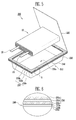
FIG. 1 is a perspective view of a pouch-type secondary battery according to an embodiment of the present invention; -
FIG. 2 is an exploded view of the secondary battery shown inFIG. 1 ; -
FIG. 3 is a view enlarging the portion A ofFIG. 2 ; -
FIG. 4 is a perspective view of a pouch-type secondary battery according to an embodiment of the present invention; -
FIG. 5 is an exploded view of the secondary battery shown inFIG. 4 ; -
FIG. 6 is a view enlarging the portion B ofFIG. 5 ; -
FIG. 7 is a perspective view of a pouch-type secondary battery according to an embodiment of the present invention; -
FIG. 8 is an exploded view of the secondary battery shown inFIG. 7 ; -
FIG. 9 is a view enlarging the portion C ofFIG. 8 ; -
FIG. 10 is a perspective view of a pouch-type secondary battery according to an embodiment of the present invention; -
FIG. 11 is an exploded view of the secondary battery shown inFIG. 10 ; -
FIG. 12 is a view enlarging the portion D ofFIG. 11 ; and -
FIG. 13 is a perspective view showing the front of a pouch-type secondary battery according to an embodiment of the present invention. - Referring to
FIGS. 1 and2 , a pouch-typesecondary battery 100 according to the present embodiment includes anelectrode assembly 10, a pouch-type case 110 accommodating theelectrode assembly 10, and abonding member 150 for sealing the pouch-type case 110. Thecase 110 has abonding portion 140 where thebonding member 150 for sealing thecase 110 is disposed. - First, in the
electrode assembly 10, theelectrode assembly 10 is formed by winding a first electrode plate, a second electrode plate, and a separator interposed between the electrode plates. Afirst electrode tab 20 is attached to the first electrode plate and asecond electrode tab 30 is attached to the second electrode. Theelectrode assembly 10 is electrically connected with the outside by the first andsecond electrode tabs - The negative plate includes a negative active material layer and an uncoated part. The negative active material layer is a portion coated with a negative active material on both sides or one side of a negative collector and the uncoated part is a portion without the negative active material coated in the negative collector.
- In general, the negative current collector is a material having high conductivity and is not specifically limited as long as it does not cause chemical changes. For example, the negative current collector may be made of aluminium, nickel, titanium, and calcination carbon. The negative active material layer includes a negative active material, which is a layered compound containing lithium, a conductive material improving conductivity, and a binder improving bonding force between the layered compound and the conductive material. The negative active material layer is formed by mixing the negative active material, the conductive material, and the binder with a solvent in a slurry and then applying the slurry to the negative collector. Preferably, the solvent may be NMP (N-Methyl-2-Pyrrolidone), the negative active material may be lithium cobalt oxide (LiCoO2), the conductive material may be acetylene black, and the binder may be polyvinylidene fluoride, but they are not limited thereto.
- The positive plate includes a positive active material layer and an uncoated part. The positive active material layer is coated with a positive active material on both sides or one side of a positive current collector.
- In general, the positive current collector is a conductive metal plate, and for example, may be made of copper, stainless steel, aluminium, and nickel. The positive active material layer is formed by mixing the positive active material and a binder improving bonding force of the positive active material with a solvent in a slurry and then applying the slurry to the positive collector. Preferably, the solvent may be NMP (N-Methyl-2-Pyrrolidone), the positive active material may be graphite, and the binder may be polyvinylidene fluoride, but they are not limited thereto. As described above, when graphite is used for the positive active material, the negative plate corresponding to the positive plate may have a smaller area than the positive plate. On the other hand, when tin oxide (SnO) or lithium titanium oxide (ITO) is used for the positive active material, the negative plate corresponding to the positive plate may have a larger area than the positive plate.
- The separator is interposed between the negative plate and the positive plate. The separator functions as an ion path and prevents contact between the negative plate and the positive plate. Therefore, the separator is formed of an insulating thin film having high ion transmittance and mechanical strength. For example, the separator may be porous film or non-woven fabric including polyethylene, polypropylene, or polyvinylidene fluoride.
- The
electrode assembly 10 is formed by winding the negative plate and the positive plate with the separator interposed therebetween. Theelectrode assembly 10 wound as described above is accommodated with electrolyte in thepouch case 110 and thepouch case 110 is sealed, thereby forming thesecondary battery 100. - Further, the
electrode assembly 10 includes afirst electrode tab 20 and asecond electrode tab 30. Theelectrode tabs second electrode tabs electrode tabs secondary battery 100 of the present invention, the first andsecond electrode tabs case 110 through thebonding portion 140 of the pouch-type case 110. Therefore, theelectrode assembly 10 is electrically connected with the outside by the first andsecond electrode tabs - In the
secondary battery 100 according to the present invention, the pouch-type case 110 accommodating theelectrode assembly 10 is composed of acover 120 and amain body 130. Themain body 130 of the pouch-type case 110 has ahousing portion 130a that is a space for accommodating theelectrode assembly 10 and thebonding portion 140 extending outside from the inlet of thehousing portion 130a. Thehousing portion 130a may be formed by deep-drawing an integral rectangular laminate sheet. Thecover 120 is integrally connected with one side of thebonding portion 140. Thesecondary battery 100 is manufactured by disposing theelectrode assembly 10 in thehousing portion 130a of themain body 130 and then thermal-bonding thebonding portion 140, with themain body 130 and thecover 120 in close contact. - The laminate sheet of the pouch-
type case 110 includes an inner resin layer, a metal layer, and an outer resin layer. In general, the metal layer is a thin aluminium layer and the upper and lower sides of the thin aluminium layer are covered with synthetic resin, such as polypropylene or polyethylene. Accordingly, the laminate sheet has a stacked structure including the metal layer, the inner resin layer, and the outer resin layer. Further, the inner resin layer is made of a heat adhesive resin to seal thecase 110. Therefore, the case is sealed by pressing the inner resin layer, particularly heating and pressing the bonding portion. - Conventionally, an insulating tape is attached to the electrode tabs of the pouch-type secondary battery. However, an insulating tape is not attached to the
electrode tabs electrode assembly 10 of the secondary battery according to the present invention. - The insulating tape is provided to prevent contact and short-circuit between the metal layer of the laminate sheet and the
electrode tabs type case 110. However, the insulating tape interferes with bonding of thebonding portion 140 and thecover 120 of the pouch-type case 110. Therefore, bonding of the pouch-type case 110 may be incompletely made by the insulating tape, such that a path through which moisture permeates from the outside or the electrolyte leaks from the inside to the outside may be formed. Hereafter, this is described in detail. - The pouch-
type case 110 is sealed by thermal bonding, after accommodating theelectrode assembly 10 and the electrolyte therein. In detail, thebonding portion 140 of the pouch-type case 110 and thecover 120 contacting thebonding portion 140 are pressed by a specific jig and heated above predetermined temperature. Theelectrode tabs bonding portion 140, however, interfere with controlling temperature and pressure required for the thermal bonding of thecase 110. Further, non-uniform pressure is applied by the thickness ofelectrode tabs electrode tabs electrode tabs bonding portion 140. - That is, temperature and pressure concentrate on the portions where the
electrode tabs electrode tabs electrode tabs type case 110. In particular, the insulating tapes are more damaged, when theelectrode tabs secondary battery 100, with the insulating tapes attached to theelectrode tabs - However, secondary batteries according to the present invention make it possible to improve sealability of the pouch-
type case 110 without a short-circuit between the electrode tabs and the case, even without using an insulating tape. - Referring to
FIGS. 1 and3 , an insulating tape is not attached to the first andsecond electrode tabs secondary battery 100 according to the present embodiment. Further, thecase 110 of thesecondary battery 100 according to the present embodiment further includes aseparate bonding member 150 in thehousing portion 130a and thebonding portion 140. Thebonding member 150 is only formed the bonding portion that is bonded. - As described above, the
case 110 is composed of theinner resin layer 110a, themetal layer 110b, and theouter resin layer 110c. Theinner resin layer 110a is a layer that is thermal-bonded by heat and pressure applied with theelectrode assembly 10 accommodated, and usually made of CPP (cast polypropylene). Further, theinner resin layer 110a may further include an adhesive layer. The adhesive layer supplements small bonding force of theinner resin layer 110 to themetal layer 110b. The metal layer is a layer preventing air, moisture etc. from flowing into the battery and usually made of aluminium. The outer resin layer protects the battery from the outside, such that it needs high tensile strength and weatherability to the thickness. For example, stretched nylon film may be used for the outer resin layer. - The
bonding member 150 is separately formed and disposed on theinner resin layer 110a, which is the upper surface of thebonding portion 140 of thecase 110. That is, theseparate bonding member 150 is disposed on the upper surface of thebonding portion 140. Accordingly, thebonding portion 140 that is bonded in thecase 110 has a thickness different from the other portions of the case. That is, since theseparate bonding member 150 is disposed only on thebonding portion 140, thebonding portion 140 of thecase 110 increases in thickness as much as the thickness of thebonding member 150. - The
bonding member 150 may be selectively made of any one or more of polypropylene, polyethylene, polyterephthalate, and polyacrylonitrile. - Further, the thickness of the
bonding member 150 may be 100µm to 200µm. Thebonding member 150 is likely to be damaged in the bonding or thermal bonding, when the thickness of thebonding member 150 is smaller than 100µm. Therefore, there may be a problem that current flows through the damaged portion of the bonding portion. Further, it may be difficult to seal thecase 110, when the thickness of thebonding member 150 is larger than 200µm. - Referring to
FIG. 2 , when thesecondary battery 110 is manufactured with the pouch-type case 110 including thebonding member 150, a short-circuit does not occur even without attaching an insulating tape to the first andsecond electrode tabs electrode assembly 10. As shown in the figures, the first andsecond electrodes electrode assembly 10 are exposed to the outside through thebonding portion 140 of thecase 110. Thecase 110 is bonded by pressing thebonding portion 140 at high temperature. - In the thermal bonding, the
secondary battery 110 according to the present embodiment, a short-circuit with thecase 110 does not occurred even though an insulating tape is not attached to theelectrode tabs bonding portion 140 of thecase 110 is uniformly bonded by thebonding member 150, sealability of thecase 110 is improved. As described above, thebonding member 150 is manufactured separately from the pouch-type case 110 and attached to thebonding portion 140. - Referring to
FIGS. 4 ,5 and 6 , a pouch-typesecondary battery 200 according to another embodiment includes anelectrode assembly 10, a pouch-type case 210 accommodating theelectrode assembly 10, andbonding members 250 composed of a plurality of layers to seal the pouch-type case 210. Thecase 210 has abonding portion 240 where thebonding members 250 are disposed. - The
electrode assembly 10 is formed by winding an negative plate, a positive plate, and a separator interposed between the electrode plates. Afirst electrode tab 20 is attached to the negative plate and asecond electrode plate 30 is attached to the positive plate. Theelectrode assembly 10 is electrically connected with the outside by the first andsecond electrode tabs electrode tabs electrode assembly 10 of thesecondary battery 200 according to the present embodiment are the same as those of theelectrode assembly 10 shown inFIGS. 1 to 3 , and the detailed description is not provided. - In the
secondary battery 200 according to the present embodiment, the pouch-type case 210 accommodating theelectrode assembly 10 is composed of acover 220 and amain body 230. Themain body 230 of the pouch-type case 210 has ahousing portion 230a that is a space for accommodating theelectrode assembly 10 and thebonding portion 240 extending outside from the inlet of thehousing portion 230a. Thehousing portion 230a may be formed by deep-drawing an integral rectangular laminate sheet. Thecover 220 is integrally connected with one side of thebonding portion 240. Thesecondary battery 200 according to the present embodiment is manufactured by disposing the electrode assembly in thehousing portion 230a of themain body 230 and then thermal-bonding thebonding portion 240 where thebonding members 250 are disposed, with themain body 230 and thecover 120 in close contact. - As described above, the
case 210 is composed of theouter resin layer 210a, themetal layer 210b, and theinner resin layer 210c. Theinner resin layer 210a is usually made of CPP, but may further include an adhesive layer to supplement bonding force. Themetal layer 210b is generally made of aluminium and theouter resin layer 210c may be made of stretched nylon film. Other than the above, the configuration of thecase 210 is the same as that thecase 110 shown inFIGS. 1 to 3 , and the detailed description is not provided. - Referring to
FIGS. 5 and 6 , thecase 210 of thesecondary battery 200 according to the present embodiment includes thebonding member 250 composed of a plurality of layers, which is separately manufactured. Thebonding members 250 are disposed on the upper surface of thebonding portion 240 of thecase 210. Further, thebonding members 250 are separately manufactured and disposed on thebonding portion 240, as shown inFIG. 5 . Accordingly, thebonding portion 240 of thecase 210 increases in thickness as much as the thickness of thebonding members 250 and the thickness is different from the other portions without thebonding members 250. -
FIG. 6 is a view enlarging thebonding portion 240 and thebonding members 250 disposed on the upper surface of thebonding portion 240. Thebonding member 250 is composed of a plurality of layers in the present embodiment. Thebonding members 250 may be divided into first, second, andthird bonding members FIG. 6 , thesecond boding member 250b is disposed between the first andthird bonding members second bonding member 250b may be made of the same material as theinner resin layer 210a of thecase 210, but is not limited thereto. Thesecond bonding member 250b may be made of various polymers, in accordance with the design of the secondary battery. Preferably, thesecond bonding member 250b may be made of CPP. - The
first bonding member 250a is a portion that contacts the first andsecond electrode tabs second electrode tabs first bonding member 250a. Further, thebonding portion 240 is sealed substantially by thefirst bonding member 250a, when thecover 220 and themain body 230 of thecase 210 is thermal-bonded. Further, the thickness of thefirst bonding member 250a may be 100µm to 200µm. Thefirst bonding member 250a is likely to be damaged in the bonding or thermal bonding, when the thickness of thefirst bonding member 250a is smaller than 100µm. Further, it may be difficult to seal thecase 210, when the thickness of thefirst bonding member 250a is larger than 200µm. - The
third bonding portion 250c is a portion that directly contacts thebonding portion 240 of thecase 210. Thethird bonding member 250c may be made of the same material as thesecond bonding member 250b described above. Further, thethird bonding member 250c may be made of the same material as thefirst bonding member 250a. The interface between thesecond bonding member 250b and thethird bonding member 250c is removed, when thethird bonding member 250c and thesecond bonding member 250b are made of the same material. Therefore, thebonding member 250 becomes composed of only two layers. Further, when thethird bonding member 250c and thefirst bonding member 250a are made of the same material, it does not need to discriminate the portion contacting thecover 220 of the case or the portion contacting themain body 230 in thebonding members 250. That is, the upper surface and the lower surface of thebonding members 250 is not discriminated. Therefore, it does not need to distinguish the direction of thebonding member 250 and the process efficiency is increased, when thebonding members 250 are separately manufactured and attached to thecase 210. - The
bonding members 250 of thesecondary battery 210 according to the present embodiment are shown to be composed of three layers, but as described above, the layers of thebonding member 250 may be less than three. Further, the layers of thebonding members 250 may be more than three. This depends on the kinds of materials of the layers of thebonding members 250. - As described above, the
bonding members 250 composed of a plurality of layers are disposed in thebonding portion 240 of the pouch-type case 210 according to the present embodiment. Therefore, the thickness of thebonding member 250 is added to thebonding portion 240 and the depth of thehousing portion 230a of themain body 230 correspondingly increases. - The
housing portion 230a of themain body 230 is a space accommodating theelectrode assembly 10. The depth of thehousing portion 230a depends on the thickness of theelectrode assembly 10. Thehousing portion 230a may be formed by deep drawing. The deep drawing is a method of manufacturing a container without a joint from a flat plate. A circular cylinder, a polygonal cylinder, and other complicated shapes can be achieved by the method. The resin layer of the laminate has small durability than the metal layer. Therefore, the depth of thehousing portion 230a which can be achieved by deep drawing is limited by the resin layer. - On the other hand, in the
case 210 including thebonding members 250 according to the present embodiment, the depth of thehousing portion 230a is increased by thebonding members 250 composed of a plurality of layers. That is, the thickness of thebonding portion 240 with thebonding members 250 is relatively increased as much as the thickness of thebonding members 250, by the thickness of thebonding members 250 themselves, which are composed of a plurality of layers. Accordingly, thehousing portion 230a can generally accommodate theelectrode assembly 10 having a thickness as much as the depth, which can be achieved by deep drawing, added with the thickness of thebonding members 250. - Referring to
FIGS. 7 ,8 and 9 , a pouch-typesecondary battery 300 according to another embodiment includes anelectrode assembly 10 and a pouch-type case 310 accommodating theelectrode assembly 10, the pouch type case comprising asidewall structure 350, the sidewall structure comprising aspacer 351 between first andsecond bonding members case 310 has abonding portion 340 where thesecond bonding member 350b for sealing thecase 310 is disposed. - The
electrode assembly 10 is formed by winding a negative plate, a positive plate, and a separator interposed between the electrode plates. Afirst electrode tab 20 is attached to the negative plate and asecond electrode plate 30 is attached to the positive plate. As described above, an insulating tape is not attached to theelectrode tabs electrode assembly 10 of thesecondary battery 300 according to the present embodiment is the same as theelectrode assembly 10 shown inFIGS. 1 to 3 , and the detailed description is not provided. - In the
secondary battery 300 according to the present embodiment, thecover 320 is integrally connected with one side of the main body of the pouch-type case 310 accommodating theelectrode assembly 10. The main body forms a base portion of the case, or can be seen as one part of a one-piece cover on which the sidewall structure is disposed, with thecover 320 extending from the base portion being folded over thesidewall structure 350 to form thecase 310. Thecase 310 according to the present embodiment does not undergo deep drawing. Thespacer 351 andbonding members 350a, b are separately manufactured and provided in thecase 310. - The
case 310 is composed of theouter resin layer 310a, themetal layer 210b, and theinner resin layer 210c. Theinner resin layer 310a is usually made of CPP and may further include an adhesive layer to supplement bonding force. Themetal layer 310b is generally made of aluminium and theouter resin layer 310c may be made of stretched nylon film. - A
housing portion 330a accommodating theelectrode assembly 10 is formed by thesidewall structure 350. In detail, thesidewall structure 350 having a predetermined thickness is disposed on the upper surface of thebonding portion 340 of thecase 310. Therefore, thecase 310 has ahousing portion 330a that can accommodate theelectrode assembly 10. The thickness of thehousing portion 330a formed as described above depends on the thickness of thesidewall structure 350 disposed on thebonding portion 340. - In the present embodiment, the
case 310 does not undergo deep drawing, unlike the embodiments described above. Accordingly, since deep drawing is not performed, it is possible to reduce the manufacturing cost of thesecondary battery 300. Further, the depth of the housing portion which can be achieved by deep drawing was limited. However, since thehousing portion 330a of thecase 310 is not formed by deep drawing in thesecondary battery 300 according to the present embodiment, the depth of thehousing 330a is not limited. It is therefore possible to accommodate theelectrode assembly 10 having various thicknesses. Therefore, it has the advantage of manufacturing a secondary battery for accommodating athick electrode assembly 10, that is, high capacity. Other than the above, the configuration of thecase 310 is the same as that thecase 310 shown inFIGS. 1 to 3 , and the detailed description is not provided. - As described above, in the
case 310 of thesecondary battery 300 according to the present embodiment, the space accommodating theelectrode assembly 10 inside thecase 310 is formed by thesidewall structure 350, which is now described in detail. - Referring to
FIGS. 8 and 9 , thesidewall structure 350 is disposed on the upper surface of thebonding portion 340 of thecase 310. Further, the components of thesidewall structure 350 are separately manufactured and disposed on thebonding portion 340. -
FIG. 9 is a view enlarging thebonding portion 340 and thesidewall structure 350 disposed on the upper surface of thebonding portion 340. Thesidewall structure 350 includes thespacer 351. That is, thebonding members 350 are composed of first andsecond bonding members spacer 351 disposed between the first andsecond bonding members - The
first bonding member 350a is a portion that contacts the first andsecond electrode tabs second electrode tabs first bonding member 350a. Further, thefirst bonding member 350a is a portion that is substantially thermal-bonded with thecover 320 of thecase 310. - The
first bonding member 350a may be selectively made of any one or more of polypropylene, polyethylene, polyterephthalate, and polyacrylonitrile. Further, it is preferable that the thickness of thefirst bonding member 350a may be 100µm to 200µm. Thefirst bonding member 350a is likely to be damaged in the bonding or thermal bonding, when the thickness of thefirst bonding member 350a is smaller than 100µm. Further, the electrolyte may leak due to incomplete sealing of thecase 310, when the thickness of thefirst bonding member 350a is larger than 200µm. - Further, the
second bonding member 350b is a portion contacting theinner resin layer 310a of thecase 310. The interface between thesecond bonding member 350b and the inner resin layer is unclear, when thesecond bonding member 350b is made of the same material as theinner resin layer 310a of thecase 310. Further, thesecond bonding member 350b may be made of the same material as thefirst bonding member 350a described above. In this case, it is advantageous to attach thebonding members 350a, b separately manufactured to thecase 310. That is, since it does not need to distinguish the upper surface from the lower surface of thebonding members 350, it is possible to reduce errors caused in the related process. - Further, it is possible to simplify the process, when attaching the
bonding members 350a, b to thecase 310. That is, it is possible to dispose thebonding members 350a, b between thecover 320 and the main body of the case and then attach at one time thecover 320, thebonding members 350a, b, and the main body, without separately attaching thebonding members 350 to thecase 310 and then attaching thecover 320 to thebonding member 350. Further, it is possible to reduce the manufacturing cost, because there is no need to add a process of attaching thebonding members 350 to thecase 310. The material of thesecond bonding member 350b described above is an example and may be various polymers. - Referring to
FIGS. 8 and 9 , the upper surface of thespacer 351 is covered with thefirst bonding member 350a and the lower surface is covered with thesecond bonding member 350b. - Further, the
spacer 351 should not react with the electrolyte such that theelectrode assembly 10 is not influenced by external pressure. Therefore, thespacer 351 should have high mechanical strength and anticorrosion. In general, thespacer 351 may be formed by molding metal having high strength and good forming performance, or engineering plastic. In this configuration, the metal may be aluminium, stainless steel, and nickel, and the plastic may be polycarbonate, nylon, polyamide, polybutylene terephthalate, and polyethylene terephthalate. As described above, thespacer 351 can be made of a material that maintains a constant space in thecase 310 and does not react with the electrolyte therein, such that the material is not limited. - Referring to
FIGS. 10 to 13 , a pouch-typesecondary battery 400 according to another embodiment includes anelectrode assembly 10, a pouch-type case 410 accommodating theelectrode assembly 10, and asidewall structure 450 to seal the pouch-type case 410. The overall configuration of thesecondary battery 400 of this embodiment is very similar to that shown inFigures 7 to 9 and corresponding parts have corresponding reference numerals. - Referring to
FIGS. 11 and 12 , the upper surface of thespacer 451 is covered with thefirst bonding member 450a and the lower surface is covered with thesecond bonding member 450b, andsidewall structure 450 is composed of the first andsecond bonding members spacer 451. Thehousing portion 430a is formed in thecase 410 by thespacer 451. Thespacer 451 maintains the gap between thecover 420 and the base portion of thecase 410. Further, thespacer 451 may be formed by moulding metal having high strength and good forming performance, or engineering plastic such that the electrode assembly is not influenced by external pressure. In this configuration, the metal may be aluminium, stainless steel, and nickel, and the plastic may be polycarbonate, nylon, polyamide, polybutylene terephthalate, and polyethylene terephthalate. Thespacer 451 can be made of a material that maintains a constant space in thecase 410 and does not react with the electrolyte therein, such that the material is not limited. - Referring to
FIGS. 11 to 13 , the spacer has two steps, or grooves, 451a. The twosteps 451a are spaced apart from each other and formed on the upper surface of thespacer 451. Accordingly, thesteps 451a contact thefirst bonding member 450a. Thesteps 451a are paths through which the first andsecond electrode tabs electrode assembly 10 pass. Therefore, since the first andsecond electrode tabs steps 451a, thefirst bonding member 450a presents a planar surface which provides a good bond with thecover 420. Since thesteps 451a can be formed in the process of manufacturing thespacer 451, an additional process is not needed. Further, the first andsecond electrode tabs steps 451a, thereby preventing a short-circuit. Other than the above, since the configuration and operation of thespacer 451 are the same as thespacer 351 shown inFIGS. 7 to 9 , the detailed description is not provided. - In manufacturing the secondary battery, the
spacer 451 is attached to the base portion of the case via thesecond bonding member 450b. Theelectrode assembly 10 is then placed in position with the electrode tabs in thegrooves 451a. Thefirst bonding member 450a is then disposed over the top of the electrode tabs before the case is sealed. - While the present invention has been described in connection with certain exemplary embodiments, it is to be understood that the invention is not limited to the disclosed embodiments, but, on the contrary, is intended to cover various modifications and equivalent arrangements included within the scope of the appended claims.
Claims (15)
- A pouch-type secondary battery (100, 200, 300, 400) comprising:an electrode assembly (10) having electrode tabs (20, 30);a case (110, 210, 310, 410) accommodating the electrode assembly, wherein the tabs extend outside the case, the case comprising a housing (130, 230, 330a, 430a) and a cover (120, 220, 320, 420); anda bonding member (150, 250) disposed around a periphery of the housing for bonding the cover to the housing.
- The secondary battery of claim 1, wherein the electrode tabs (20, 30) directly contact the bonding member (150, 250).
- The secondary battery of claim 1 or 2, wherein the housing (130, 230) comprises a flange portion (140, 240) and the bonding member (150, 250) is formed on the flange portion (140, 240).
- The secondary battery of any one of the preceding claims, wherein the battery is sealed by thermally bonding the cover (120), the bonding member (150) and the housing (130) together.
- The secondary battery of any one of the preceding claims, wherein the housing comprises an inner resin layer (110a, 210a), an outer resin layer (110c, 210c) and a metal layer (110b, 210b) sandwiched between the inner resin layer and the outer resin layer, wherein the bonding member (150, 250) is formed on the inner resin layer (110a, 210a).
- The secondary battery of claim 5, wherein the inner resin layer includes an adhesive layer.
- The secondary battery of any one of the preceding claims, wherein the bonding member comprises one or more bonding layers (150, 250a, 250b, 250c).
- The secondary battery of any one of the preceding claims, wherein the bonding member (150, 250a, 350a, 450a) has a thickness between 100µm and 200µm.
- The secondary battery of any one of the preceding claims, wherein the bonding member comprises one or more of polypropylene, polyethylene, polyethelyne terephthalate or polyacrylonitrile.
- The secondary battery of any one of the preceding claims, wherein the case (300, 400) comprises:a spacer (351, 451); andfirst and second bonding members (350a, 350b; 450a, 450b) on either side of the spacer;wherein the cover (320) is bonded to the first bonding member.
- The secondary battery of claim 10, further comprising:an inner resin layer (310a);an outer resin layer (310c);a metal layer (310b) between the inner and outer resin layers,wherein the second bonding member (350b) is disposed between the spacer and the inner resin layer (310a).
- The secondary battery of claim 11, wherein the inner resin layer (310a, 410a), the metal layer (310b, 410b) and the outer resin layer (310c, 410c) extend to form the cover (320, 420).
- The secondary battery of claim 10, 11 or 12, wherein the spacer comprises grooves (451a) for receiving the electrode tabs, and the first bonding member (450a) is arranged on top of the electrode tabs when the tabs are located in the grooves.
- A method of making a secondary battery, the method comprising:providing a case for an electrode assembly having electrode tabs, the case having a cover;disposing a bonding member on a bonding portion of the case;placing the electrode assembly in the case so that electrode tabs extend out of the case; andthermally bonding the cover, the bonding member and the bonding portion of the case together.
- The method of claim 14, further comprising locating the electrode tabs in grooves (451a) in a side of the case prior to disposing the bonding member on the bonding portion of the case.
Applications Claiming Priority (2)
| Application Number | Priority Date | Filing Date | Title |
|---|---|---|---|
| US35702410P | 2010-06-21 | 2010-06-21 | |
| US13/085,412 US20110311862A1 (en) | 2010-06-21 | 2011-04-12 | Secondary battery |
Publications (1)
| Publication Number | Publication Date |
|---|---|
| EP2408039A1 true EP2408039A1 (en) | 2012-01-18 |
Family
ID=44653711
Family Applications (1)
| Application Number | Title | Priority Date | Filing Date |
|---|---|---|---|
| EP11166792A Withdrawn EP2408039A1 (en) | 2010-06-21 | 2011-05-19 | Secondary battery and method of making a secondary battery |
Country Status (5)
| Country | Link |
|---|---|
| US (1) | US20110311862A1 (en) |
| EP (1) | EP2408039A1 (en) |
| JP (1) | JP5679196B2 (en) |
| KR (1) | KR101271878B1 (en) |
| CN (1) | CN102290536A (en) |
Cited By (1)
| Publication number | Priority date | Publication date | Assignee | Title |
|---|---|---|---|---|
| DE102021208034A1 (en) | 2021-07-26 | 2023-01-26 | Volkswagen Aktiengesellschaft | Process for manufacturing an energy cell and energy cell |
Families Citing this family (26)
| Publication number | Priority date | Publication date | Assignee | Title |
|---|---|---|---|---|
| EP2822055B1 (en) * | 2012-02-29 | 2017-12-27 | Nisshin Steel Co., Ltd. | Exterior material for laminated battery, method for manufacturing exterior material for laminated battery, method for manufacturing laminated battery and laminated battery |
| KR101495953B1 (en) * | 2012-05-10 | 2015-02-25 | 주식회사 엘지화학 | Pouch for secondary battery and secondary battery using the same |
| WO2015080307A1 (en) * | 2013-11-27 | 2015-06-04 | 주식회사 엘지화학 | Pouch for secondary battery and secondary battery comprising same |
| KR102256294B1 (en) * | 2014-07-14 | 2021-05-26 | 삼성에스디아이 주식회사 | Flexible secondary battery |
| KR102222118B1 (en) * | 2014-07-14 | 2021-03-03 | 삼성에스디아이 주식회사 | Flexible secondary battery |
| KR102222112B1 (en) * | 2014-07-16 | 2021-03-03 | 삼성에스디아이 주식회사 | Flexible secondary battery |
| KR102361705B1 (en) * | 2015-03-03 | 2022-02-10 | 삼성에스디아이 주식회사 | Rechargeable battery having cover |
| US10573856B2 (en) * | 2015-05-14 | 2020-02-25 | GM Global Technology Operations LLC | Barrier layer coatings for battery pouch cell seal |
| KR20170002013A (en) * | 2015-06-29 | 2017-01-06 | 에스케이이노베이션 주식회사 | Secondary battery and method for manufacturing same |
| KR101975988B1 (en) * | 2015-07-17 | 2019-05-07 | 주식회사 엘지화학 | Pouch for secondary battery and Pouch-typed secondary battery comprising the same |
| KR20170026230A (en) * | 2015-08-27 | 2017-03-08 | 주식회사 엘지화학 | apparatus for sealing secondary battery |
| KR102112670B1 (en) * | 2015-10-28 | 2020-05-19 | 주식회사 엘지화학 | Battery Cell of Venting Structure Using Taping |
| EP3428992B1 (en) * | 2016-03-10 | 2020-04-29 | Nissan Motor Co., Ltd. | Battery pack |
| KR102106999B1 (en) * | 2016-04-25 | 2020-05-06 | 주식회사 엘지화학 | Battery Cell with Improved Insulative Performance of Electrode Lead and Excellent Productivity on Standardized Structure and Battery Pack Comprising the Same |
| KR102222114B1 (en) * | 2016-07-21 | 2021-03-03 | 삼성에스디아이 주식회사 | Secondary battery |
| US10727453B2 (en) * | 2016-09-28 | 2020-07-28 | Lg Chem, Ltd. | Method for sealing pouch casing of secondary battery |
| KR102379221B1 (en) * | 2017-01-20 | 2022-03-28 | 주식회사 엘지에너지솔루션 | Pouch-type secondary battery case and lithium secondary battery comprising the same |
| KR102379222B1 (en) * | 2017-01-20 | 2022-03-28 | 주식회사 엘지에너지솔루션 | Pouch-type case for secondary battery |
| CN108428811A (en) * | 2017-02-15 | 2018-08-21 | 宁德新能源科技有限公司 | Soft-package battery |
| KR102414195B1 (en) * | 2017-11-07 | 2022-06-29 | 주식회사 엘지에너지솔루션 | Pouch for rechargeable battery and rechargeable battery comprising the same |
| KR102164254B1 (en) * | 2017-11-15 | 2020-10-12 | 주식회사 엘지화학 | The Secondary Battery And The Method For Manufacturing Thereof, The Pouch For Secondary Battery And The Method For Manufacturing Thereof |
| KR102264635B1 (en) | 2017-11-23 | 2021-06-15 | 주식회사 엘지에너지솔루션 | The Pouch Type Secondary Battery |
| CN110311062B (en) * | 2018-03-27 | 2021-09-21 | 比亚迪股份有限公司 | A safety cover and battery package for tray |
| KR102132844B1 (en) * | 2018-07-17 | 2020-07-10 | 삼성에스디아이 주식회사 | Secondary battery |
| KR102364469B1 (en) | 2018-12-07 | 2022-02-17 | 주식회사 엘지에너지솔루션 | Laminate Sheet for Battery Case Having Thickness Variation and Pouch-type Battery Case Manufactured Using the Same |
| KR102083031B1 (en) * | 2019-03-25 | 2020-04-23 | 김용태 | Vapor chamber laminating method and structure therefor |
Citations (3)
| Publication number | Priority date | Publication date | Assignee | Title |
|---|---|---|---|---|
| US20030064286A1 (en) * | 2001-09-28 | 2003-04-03 | Mitsubishi Denki Kabushiki Kaisha | Nonaqueous electrolyte battery and method of manufacturing same |
| US20030118900A1 (en) * | 2001-12-21 | 2003-06-26 | Nec Corporation | Non-aqueous electrolyte battery |
| EP1667251A1 (en) * | 2003-08-08 | 2006-06-07 | NEC Lamilion Energy, Ltd. | Cell coated with film and manufacturing method thereof |
Family Cites Families (12)
| Publication number | Priority date | Publication date | Assignee | Title |
|---|---|---|---|---|
| CA2093137A1 (en) * | 1991-08-09 | 1993-02-10 | Kazuo Murata | Film type battery |
| JPH11162421A (en) * | 1997-11-26 | 1999-06-18 | Toshiba Battery Co Ltd | Sheet type battery |
| CA2285946C (en) * | 1998-02-05 | 2007-05-15 | Dai Nippon Printing Co., Ltd. | Sheet for cell case and cell device |
| JP2000182579A (en) * | 1998-12-16 | 2000-06-30 | Toshiba Battery Co Ltd | Plate-like polymer electrolyte battery |
| KR100342045B1 (en) * | 1999-04-16 | 2002-06-27 | 김순택 | Secondary battery |
| KR100647566B1 (en) * | 1999-11-17 | 2006-11-17 | 삼성에스디아이 주식회사 | Lithium Polymer battery and method for manufacturing the same |
| JP2002343314A (en) * | 2001-05-21 | 2002-11-29 | Toppan Printing Co Ltd | Outer packaging material for lithium ion battery |
| JP4508477B2 (en) * | 2001-06-20 | 2010-07-21 | 大日本印刷株式会社 | Battery lead wire film and battery packaging material using the same |
| JP4381766B2 (en) * | 2003-10-06 | 2009-12-09 | 藤森工業株式会社 | Insulating sealing film, method for producing the same, and method for producing a package |
| KR100917734B1 (en) * | 2007-07-19 | 2009-09-21 | 삼성에스디아이 주식회사 | Pouch Type Lithium Secondary Battery |
| JP5308696B2 (en) * | 2008-03-17 | 2013-10-09 | 藤森工業株式会社 | Sealing film and electrode with sealing film |
| JP5256990B2 (en) * | 2008-10-17 | 2013-08-07 | 大日本印刷株式会社 | Electrochemical cell and method for producing the same |
-
2011
- 2011-04-12 US US13/085,412 patent/US20110311862A1/en not_active Abandoned
- 2011-05-19 EP EP11166792A patent/EP2408039A1/en not_active Withdrawn
- 2011-06-16 CN CN201110167129A patent/CN102290536A/en active Pending
- 2011-06-16 KR KR1020110058506A patent/KR101271878B1/en not_active IP Right Cessation
- 2011-06-20 JP JP2011136088A patent/JP5679196B2/en not_active Expired - Fee Related
Patent Citations (3)
| Publication number | Priority date | Publication date | Assignee | Title |
|---|---|---|---|---|
| US20030064286A1 (en) * | 2001-09-28 | 2003-04-03 | Mitsubishi Denki Kabushiki Kaisha | Nonaqueous electrolyte battery and method of manufacturing same |
| US20030118900A1 (en) * | 2001-12-21 | 2003-06-26 | Nec Corporation | Non-aqueous electrolyte battery |
| EP1667251A1 (en) * | 2003-08-08 | 2006-06-07 | NEC Lamilion Energy, Ltd. | Cell coated with film and manufacturing method thereof |
Cited By (1)
| Publication number | Priority date | Publication date | Assignee | Title |
|---|---|---|---|---|
| DE102021208034A1 (en) | 2021-07-26 | 2023-01-26 | Volkswagen Aktiengesellschaft | Process for manufacturing an energy cell and energy cell |
Also Published As
| Publication number | Publication date |
|---|---|
| CN102290536A (en) | 2011-12-21 |
| US20110311862A1 (en) | 2011-12-22 |
| JP2012004122A (en) | 2012-01-05 |
| JP5679196B2 (en) | 2015-03-04 |
| KR101271878B1 (en) | 2013-06-05 |
| KR20110139108A (en) | 2011-12-28 |
Similar Documents
| Publication | Publication Date | Title |
|---|---|---|
| EP2408039A1 (en) | Secondary battery and method of making a secondary battery | |
| KR100879893B1 (en) | Secondary Battery Having Safety-improved Sealing Portion | |
| JP5281836B2 (en) | Electrode assembly and secondary battery using the same | |
| US9034498B2 (en) | Secondary battery | |
| CN105609693B (en) | Electrode assembly and battery pack having the same | |
| US9017856B2 (en) | Stacked battery with electrode having break portion | |
| KR101229228B1 (en) | Secondary Battery with Improved Moisture Barrier | |
| KR101082960B1 (en) | Secondary Battery with Excellent Durability | |
| KR100892049B1 (en) | Small Battery Pack | |
| JP7250209B2 (en) | Battery case for secondary battery and method for manufacturing pouch-type secondary battery | |
| US11063328B2 (en) | Secondary battery including insulating member with grooves | |
| JP2020030899A (en) | Secondary battery | |
| WO2017098995A1 (en) | Electrochemical device and method for manufacturing same | |
| JP2017126558A (en) | Electrochemical cell and manufacturing method of electrochemical cell | |
| CN116490998A (en) | Secondary battery | |
| JP4397175B2 (en) | Electricity storage element | |
| JP7299816B2 (en) | Stacked battery manufacturing method, stacked battery manufacturing apparatus, and stacked battery | |
| KR101379691B1 (en) | Secondary battery capable of re-injecting electrolyte | |
| JP2020170636A (en) | Laminated battery | |
| KR102389468B1 (en) | Insulating tape | |
| WO2024176792A1 (en) | Sealed battery | |
| JP7493970B2 (en) | Electrochemical cell and method of manufacturing same | |
| EP4164051A1 (en) | Secondary battery | |
| EP4195342A1 (en) | Secondary battery | |
| WO2022196460A1 (en) | Electrochemical cell |
Legal Events
| Date | Code | Title | Description |
|---|---|---|---|
| AK | Designated contracting states |
Kind code of ref document: A1 Designated state(s): AL AT BE BG CH CY CZ DE DK EE ES FI FR GB GR HR HU IE IS IT LI LT LU LV MC MK MT NL NO PL PT RO RS SE SI SK SM TR |
|
| AX | Request for extension of the european patent |
Extension state: BA ME |
|
| PUAI | Public reference made under article 153(3) epc to a published international application that has entered the european phase |
Free format text: ORIGINAL CODE: 0009012 |
|
| 17P | Request for examination filed |
Effective date: 20120321 |
|
| STAA | Information on the status of an ep patent application or granted ep patent |
Free format text: STATUS: THE APPLICATION HAS BEEN WITHDRAWN |
|
| 18W | Application withdrawn |
Effective date: 20160616 |