US9007697B2 - Zoom lens and imaging apparatus - Google Patents
Zoom lens and imaging apparatus Download PDFInfo
- Publication number
- US9007697B2 US9007697B2 US14/100,036 US201314100036A US9007697B2 US 9007697 B2 US9007697 B2 US 9007697B2 US 201314100036 A US201314100036 A US 201314100036A US 9007697 B2 US9007697 B2 US 9007697B2
- Authority
- US
- United States
- Prior art keywords
- lens
- lens group
- zoom
- conditional formula
- zoom lens
- Prior art date
- Legal status (The legal status is an assumption and is not a legal conclusion. Google has not performed a legal analysis and makes no representation as to the accuracy of the status listed.)
- Expired - Fee Related
Links
- 238000003384 imaging method Methods 0.000 title claims description 35
- 230000003287 optical effect Effects 0.000 claims abstract description 59
- 230000004075 alteration Effects 0.000 description 85
- 230000000694 effects Effects 0.000 description 51
- 239000000463 material Substances 0.000 description 19
- 238000010586 diagram Methods 0.000 description 18
- 230000009467 reduction Effects 0.000 description 18
- 230000002349 favourable effect Effects 0.000 description 10
- 238000012937 correction Methods 0.000 description 9
- NAWXUBYGYWOOIX-SFHVURJKSA-N (2s)-2-[[4-[2-(2,4-diaminoquinazolin-6-yl)ethyl]benzoyl]amino]-4-methylidenepentanedioic acid Chemical compound C1=CC2=NC(N)=NC(N)=C2C=C1CCC1=CC=C(C(=O)N[C@@H](CC(=C)C(O)=O)C(O)=O)C=C1 NAWXUBYGYWOOIX-SFHVURJKSA-N 0.000 description 8
- 206010010071 Coma Diseases 0.000 description 4
- 230000007423 decrease Effects 0.000 description 4
- 238000004519 manufacturing process Methods 0.000 description 4
- 230000008859 change Effects 0.000 description 3
- 239000006059 cover glass Substances 0.000 description 3
- 239000000470 constituent Substances 0.000 description 2
- 230000003247 decreasing effect Effects 0.000 description 2
- 238000013461 design Methods 0.000 description 2
- 230000014509 gene expression Effects 0.000 description 2
- 230000007246 mechanism Effects 0.000 description 2
- 230000005499 meniscus Effects 0.000 description 2
- 238000000576 coating method Methods 0.000 description 1
- 239000006185 dispersion Substances 0.000 description 1
- 238000000034 method Methods 0.000 description 1
- 238000012986 modification Methods 0.000 description 1
- 230000004048 modification Effects 0.000 description 1
- 238000000465 moulding Methods 0.000 description 1
- 230000008569 process Effects 0.000 description 1
- 238000012545 processing Methods 0.000 description 1
Images






Classifications
-
- G—PHYSICS
- G02—OPTICS
- G02B—OPTICAL ELEMENTS, SYSTEMS OR APPARATUS
- G02B15/00—Optical objectives with means for varying the magnification
- G02B15/14—Optical objectives with means for varying the magnification by axial movement of one or more lenses or groups of lenses relative to the image plane for continuously varying the equivalent focal length of the objective
- G02B15/16—Optical objectives with means for varying the magnification by axial movement of one or more lenses or groups of lenses relative to the image plane for continuously varying the equivalent focal length of the objective with interdependent non-linearly related movements between one lens or lens group, and another lens or lens group
- G02B15/177—Optical objectives with means for varying the magnification by axial movement of one or more lenses or groups of lenses relative to the image plane for continuously varying the equivalent focal length of the objective with interdependent non-linearly related movements between one lens or lens group, and another lens or lens group having a negative front lens or group of lenses
-
- G—PHYSICS
- G02—OPTICS
- G02B—OPTICAL ELEMENTS, SYSTEMS OR APPARATUS
- G02B13/00—Optical objectives specially designed for the purposes specified below
- G02B13/001—Miniaturised objectives for electronic devices, e.g. portable telephones, webcams, PDAs, small digital cameras
- G02B13/009—Miniaturised objectives for electronic devices, e.g. portable telephones, webcams, PDAs, small digital cameras having zoom function
-
- G—PHYSICS
- G02—OPTICS
- G02B—OPTICAL ELEMENTS, SYSTEMS OR APPARATUS
- G02B15/00—Optical objectives with means for varying the magnification
- G02B15/14—Optical objectives with means for varying the magnification by axial movement of one or more lenses or groups of lenses relative to the image plane for continuously varying the equivalent focal length of the objective
-
- G—PHYSICS
- G02—OPTICS
- G02B—OPTICAL ELEMENTS, SYSTEMS OR APPARATUS
- G02B15/00—Optical objectives with means for varying the magnification
- G02B15/14—Optical objectives with means for varying the magnification by axial movement of one or more lenses or groups of lenses relative to the image plane for continuously varying the equivalent focal length of the objective
- G02B15/142—Optical objectives with means for varying the magnification by axial movement of one or more lenses or groups of lenses relative to the image plane for continuously varying the equivalent focal length of the objective having two groups only
- G02B15/1425—Optical objectives with means for varying the magnification by axial movement of one or more lenses or groups of lenses relative to the image plane for continuously varying the equivalent focal length of the objective having two groups only the first group being negative
-
- G—PHYSICS
- G02—OPTICS
- G02B—OPTICAL ELEMENTS, SYSTEMS OR APPARATUS
- G02B15/00—Optical objectives with means for varying the magnification
- G02B15/14—Optical objectives with means for varying the magnification by axial movement of one or more lenses or groups of lenses relative to the image plane for continuously varying the equivalent focal length of the objective
- G02B15/16—Optical objectives with means for varying the magnification by axial movement of one or more lenses or groups of lenses relative to the image plane for continuously varying the equivalent focal length of the objective with interdependent non-linearly related movements between one lens or lens group, and another lens or lens group
Definitions
- the present invention is related to a zoom lens and an imaging apparatus. Particularly, the present invention is related to a zoom lens which can be favorably utilized in miniature cameras and portable terminal devices, and to an imaging apparatus equipped with such a zoom lens.
- zoom lenses of the two group or the three group type having leading negative lens groups are well known as zoom lenses to be provided in compact digital cameras, compact video cameras, and portable terminal devices.
- Japanese Unexamined Patent Publication No. 2010-091948 discloses examples of a two group type zoom lens and a three group type zoom lens.
- aberrations can be corrected more advantageously by providing lenses toward the image side of the second lens group to adopt a three group configuration.
- this configuration increases the degree of freedom in design. Therefore, the advantageous effects of improved performance, miniaturization, and increased variable magnification ratio can be obtained.
- zoom lenses of the two group type and the three group type which are employed in compact digital cameras and the like, that have a configuration in which the first lens group is constituted by a negative lens and a positive lens provided in this order from the object side. Between these two lenses, the positive lens is easier to form using a plastic material, from the viewpoint of molding properties.
- Japanese Unexamined Patent Publication No. 2007-025373 discloses that a positive lens of a first lens group is formed by a material having a refractive index of 1.58 and an Abbe's number of 30.9.
- Japanese Unexamined Patent Publication No. 2007-187740 discloses that a positive lens of a first lens group is formed by a material having a refractive index of 1.61 and an Abbe's number of 26.6. It is preferable for the difference between the Abbe's numbers of the positive lens of the first lens group and a negative lens of the first lens group to be great. Therefore, it is desirable for a material having a smaller Abbe's number to be employed for the positive lens.
- Japanese Unexamined Patent Publication No. 2006-039182 and U.S. Patent Application Publication No. 20070171544 disclose that a material having an Abbe's number within a range from 23 to 24 is employed as the material of a positive lens, in order to increase the difference between the Abbe's numbers of the positive lens and a negative lens of the first lens group
- variable magnification ratios of the zoom lenses disclosed in Japanese Unexamined Patent Publication No. 2007-025373 and Japanese Unexamined Patent Publication No. 2007-187740 are approximately 2.4 and approximately 2.0, respectively. It can be said that such variable magnification ratios are too small to secure superiority as zoom lenses.
- the zoom lenses disclosed in Japanese Unexamined Patent Publication No. 2006-039182 and U.S. Patent Application Publication No. 20070171544 employ a material having an Abbe's number within a range from 23 to 24 for the positive lens of the first lens group.
- the negative lenses of the first lens groups of the zoom lenses disclosed in Japanese Unexamined Patent Publication No. 2006-039182 and U.S. Patent Application Publication No. 20070171544 have refractive indices of 1.75 or greater and small Abbe's numbers. That is, it is considered that the zoom lenses disclosed in these documents are based on designs that prioritize miniaturization of lens systems over correction of chromatic aberrations.
- a low refractive index/low dispersion material to be employed for a negative lens of a first lens group.
- a low refractive index/low dispersion material it is preferable for a low refractive index/low dispersion material to be employed for a negative lens of a first lens group.
- the present invention has been developed in view of the foregoing circumstances. It is an object of the present invention to provide a two lens group zoom lens that can secure a variable magnification ratio of approximately 3 ⁇ with a small number of lenses, that can achieve cost reduction by employing plastic lenses, and that can realize favorable optical performance.
- a first lens of the present invention comprises:
- the distance between the first lens group and the second lens group changing when changing magnification
- the first lens group comprising a first lens having a negative refractive power and a second lens, which is plastic, having a positive refractive power;
- Nd1n is the refractive index of the first lens with respect to the d line
- Nd1p and ⁇ d1p are the refractive index and the Abbe's number of the second lens with respect to the d line, respectively
- d2 is the spatial distance between the first lens and the second lens along an optical axis
- fw is the focal length of the entire system at the wide angle end.
- the “second lens group” of the zoom lens of the present invention is not necessarily constituted by a plurality of lenses, and may be a lens group constituted by a single lens. Cemented lenses may be employed as the lenses that constitute the second lens group. In the case that cemented lenses are employed, they will be counted as n lenses if they are constituted by n lenses cemented together. Further, the zoom lens of the present invention may further comprise other lens groups in addition to the first lens group and the second lens group.
- zoom lens of the present invention and “zoom lens according to the present invention” in the present specification refer to both the first zoom lens of the present invention and the second zoom lens of the present invention to be described later, unless particularly noted.
- the surface shapes and the signs of refractive powers of the lenses of the zoom lens of the present invention will be those in the paraxial regions for lenses that include aspherical surfaces.
- a second zoom lens of the present invention comprises:
- the distance between the first lens group and the second lens group changing when changing magnification
- the first lens group comprising a negative lens most toward the object side and a plastic positive lens
- Nd1p and ⁇ d1p are the refractive index and the Abbe's number of the second lens with respect to the d line, respectively
- Y is a maximum image height
- TL is the distance along an optical axis from the surface of the lens most toward the object side in the first lens group to an imaging surface when the first lens group is positioned most toward the object side.
- the first lens group of the second zoom lens of the present invention may further comprise other lenses in addition to the negative lens and the positive lens.
- Cemented lenses may be employed as the lenses that constitute the first lens group. In the case that cemented lenses are employed, they will be counted as n lenses if they are constituted by n lenses cemented together.
- Nd1n is the refractive index of the negative lens of the first lens group most toward the object side with respect to the d line.
- the first lens group prefferably be constituted by only two lenses, a first lens having a negative refractive power and a second lens having a positive refractive power, provided in this order from the object side.
- the second zoom lens is configured in this manner, it is desirable for the second zoom lens to satisfy the conditional formula: 0.2 ⁇ d 2/ fw ⁇ 0.5 (4)
- f2 is the spatial distance along the optical axis between the first lens and the second lens
- fw is the focal length of the entire system at the wide angle end.
- the second lens group in the zoom lens of the present invention, it is desirable for the second lens group to comprise at least one negative lens, and for the zoom lens to satisfy the following conditional formulae: 1.60 ⁇ Nd 2 n ⁇ 1.70 (6) 20.0 ⁇ d 2 n ⁇ 28.0 (7)
- Nd2n and ⁇ d2n are the refractive index and the Abbe's number of the negative lens with respect to the d line, respectively.
- the second lens group in the zoom lens of the present invention, it is desirable for the second lens group to comprise only one negative lens, and for the negative lens to be a plastic lens.
- the zoom lens of the present invention it is desirable for the zoom lens of the present invention to satisfy the following conditional formula: 0.5 ⁇ ( Rpr+Rpf )/( Rpr ⁇ Rpf ) ⁇ 6.2 (8)
- Rpf is the paraxial radius of curvature of the surface of the plastic lens having the positive refractive power provided in the first lens group toward the object side
- Rpr is the paraxial radius of curvature of the surface of the plastic lens having the positive refractive power provided in the first lens group toward the image side
- the second lens group may be constituted by two positive lenses and one negative lens.
- the zoom lens of the present invention it is desirable for the zoom lens of the present invention to practically only comprise the first lens group and the second lens group as lens groups.
- the expression “practically only comprise the first lens group and the second lens group as lens groups” means that the zoom lens may also include lenses that practically have any power, optical elements other than lenses such as aperture stops and cover glass, and mechanical components such as lens flanges, a lens barrel, an imaging element, a blur correcting mechanism, etc.
- the zoom lens of the present invention it is preferable for the zoom lens of the present invention to satisfy the following conditional formula: 48 ⁇ d 1 n ⁇ 65 (9)
- ⁇ d1n is the Abbe's number of the negative lens of the first lens group which is provided most toward the object side.
- the zoom lens of the present invention it is desirable for the zoom lens of the present invention to satisfy the following conditional formula: 0.45 ⁇ M 2/ ft ⁇ 0.75 (10)
- M2 is the amount of movement of the second lens group when changing magnification from the wide angle end to the telephoto end
- ft is the focal length of the entire system at the telephoto end.
- the zoom lens of the present invention it is desirable for the zoom lens of the present invention to satisfy the following conditional formula: 0.22 ⁇ d 12 t/d 2 gt ⁇ 0.60 (11)
- d12t is the spatial distance along the optical axis from the surface of a lens of the first lens group most toward the image side to the surface of a lens of the second lens group most toward the object side when the zoom lens is focused on an object at infinity at the telephoto end
- d2gt is the distance along the optical axis from the surface of a lens of the second lens group most toward the object side to the surface of the lens of the second lens group most toward the image side.
- the zoom lens of the present invention it is desirable for the zoom lens of the present invention to satisfy the following conditional formula: 5.8 ⁇ TLw/fw ⁇ 8.4 (12)
- TLw is the distance from the surface of the first lens most toward the object side to an imaging surface along the optical axis at the wide angle end
- fw is the focal length of the entire system at the wide angle end.
- a positive lens to be provided most toward the object side in the second lens group, and for the zoom lens of the present invention to satisfy the following conditional formulae: 1.48 ⁇ Nd 2 p ⁇ 1.65 (13) 45 ⁇ d 2 p ⁇ 65 (14)
- Nd2p and ⁇ d2p are the refractive index and the Abbe's number of the positive lens with respect to the d line, respectively.
- the negative lens provided most toward the object side in the first lens group is an aspherical lens
- the negative lens is a plastic lens in order to reduce cost
- the plastic lens having the positive refractive power provided in the first lens group is an aspherical lens.
- the lens provided cost toward the object side in the second lens group it is preferable for the lens provided cost toward the object side in the second lens group to be an aspherical lens, and further for this lens to be a plastic lens in order to reduce cost.
- the plastic lens having the positive refractive power provided in the first lens group it is preferable for the plastic lens having the positive refractive power provided in the first lens group to be an aspherical lens.
- the lens provided most toward the image side in the second lens group to be an aspherical lens, and further for this lens to be a plastic lens in order to reduce cost.
- all of the lens systems it is preferable for all of the lens systems to be constituted by five or fewer lenses.
- the second lens group may be constituted by one positive lens and one negative lens. Further, all of the lenses of the lens systems may be plastic lenses.
- the zoom lens of the present invention it is preferable for a configuration to be adopted, wherein the entirety of the second lens group or a portion of the lenses of the second lens group is moved along the optical axis when focusing from infinity to a near distance. More specifically, when the second lens group is constituted by the third lens having a positive refractive power, the fourth lens having a negative refractive power, and the fifth lens having a positive refractive power, in this order from the object side, it is preferable for only the fifth lens to be moved along the optical axis.
- conditional, formulae (1), (3), (5), (6), (8), and (9) are as follows: 1.48 ⁇ Nd 1 n ⁇ 1.70 (1′) 19 ⁇ d 1 p ⁇ 24 (3′′) 55 ⁇ Y ⁇ TL ⁇ 530 (5′) 1.60 ⁇ Nd 2 n ⁇ 1.69 (6′) 1.6 ⁇ ( Rpr+Rpf )/( Rpr ⁇ Rpf ) ⁇ 6.1 (8′) 50 ⁇ d 1 n ⁇ 65 (9′) Note that Conditional Formula (3′′) is more preferable than previously listed Conditional Formula (3′).
- the imaging apparatus of the present invention is characterized by being equipped with the first or the second zoom lens of the present invention described above.
- the first zoom lens according to the present invention comprises: the first lens group having a negative refractive power; and the second lens group having a positive refractive power, provided in this order from an object side; the distance between the first lens group and the second lens group changing when changing magnification; and the zoom lens satisfying the aforementioned conditional formulae (1) through (4) when Nd1n is the refractive index of the first lens with respect to the d line, Nd1p and ⁇ d1p are the refractive index and the Abbe's number of the second lens with respect to the d line, respectively, d2 is the spatial distance between the first lens and the second lens along an optical axis, and fw is the focal length of the entire system at the wide angle end. Therefore, a variable magnification ratio of approximately 3 ⁇ can be secured with a small number of lenses, while achieving cost reduction by the use of plastic lenses and realizing favorable optical performance.
- Conditional Formula (1) determines the refractive index of the negative lens (the first lens) provided most toward the object side in the first lens group.
- the positive lens (the second lens) provided in the first lens group is constituted by a plastic material having the optical properties indicated by Conditional Formula (2) and Conditional Formula (3) and the value of Nd1n is greater than or equal to the upper limit defined in Conditional Formula (1), the power of the negative lens provided most toward the object side in the first lens group and the power of the positive lens in the first lens group will become great. As a result, correction of spherical aberrations and coma aberrations becomes difficult, which is not preferable.
- Conditional Formula (2) determines the refractive index of the positive lens formed by plastic provided in the first lens group. If the value of Nd1p is less than or equal to the lower limit defined in Conditional Formula (2), the radius of curvature (approximated radius of curvature) of the second lens will become great. As a result, the occurrence of various types of aberrations and lateral chromatic aberration will increase, which is not preferable. Inversely, if the value of Nd1p is greater than or equal to the upper limit defined in Conditional Formula (2), astigmatic aberration becomes great, which is not preferable. In addition, it becomes difficult to select a plastic material having favorable optical proper ties. The above shortcomings can be prevented in the case that Conditional Formula (2) is satisfied.
- Conditional Formula (3) determines the Abbe's number of the positive lens formed by plastic provided in the first lens group. If the value of ⁇ d1p is less than or equal to the lower limit defined in Conditional Formula (3), it becomes difficult to correct longitudinal chromatic aberration and lateral chromatic aberration in a balanced manner, which is not preferable. Inversely, if the value of ⁇ d1p is greater than or equal to the upper limit defined in Conditional Formula (3), the difference in Abbe's numbers between the positive lens and the negative lens provided in the first lens group decreases, and it will become necessary to increase the power of the lenses in order to correct chromatic aberrations. As a result, correction of spherical aberration and astigmatic aberration will become difficult, which is not preferable. The above shortcomings can be prevented in the case that Conditional Formula (3) is satisfied.
- Conditional Formula (4) determines the relationship between the spatial distance between the negative lens and the positive lens of the first lens group and the focal length of the entire system at the wide angle end. If the value of d2/fw is less than or equal to the lower limit defined in Conditional Formula (4), such a small distance is advantageous from the viewpoint of miniaturization, but is not preferable because correction of spherical aberration will become difficult. Inversely, if the value of d2/fw is greater than or equal to the upper limit defined in Conditional formula (4), the first lens group will become large as a whole, which is not preferable. The above shortcomings can be prevented in the case that Conditional Formula (4) is satisfied.
- the second zoom lens according to the present invention comprises: the first lens group having a negative refractive power; and the second lens group having a positive refractive power, provided in this order from an object side; the distance between the first lens group and the second lens group changing when changing magnification; the first lens group comprising a negative lens most toward the object side and a plastic positive lens; and the zoom lens satisfying Conditional Formulae (2′), (3′), and (5) when Nd1p and ⁇ d1p are the refractive index and the Abbe's number of the second lens with respect to the d line, respectively, Y is a maximum image height, and TL is the distance along an optical axis when the first lens group is positioned most toward the object side. Therefore, a variable magnification ratio of approximately 3 ⁇ can be secured with a small number of lenses, while achieving cost reduction by the use of plastic lenses, and realizing favorable optical performance.
- Conditional Formula (5) determines the product of the maximum image height and the total length of the optical system. If the value of Y ⁇ TL is greater than or equal to the upper limit defined in Conditional Formula (5), the size of a compact camera will increase, which is not preferable from the viewpoint of portability. Inversely, if the value of Y ⁇ TL is less than or equal to the lower limit defined in Conditional Formula (5), the zoom lens will become extremely compact, but the number of pixels of imaging elements that can be applied will decrease. Alternatively, if the number of pixels is maintained the same, the pixel size is decreased. In either case, image quality will deteriorate, which is not preferable. The above shortcomings can be prevented in the case that Conditional Formula (5) is satisfied.
- the second zoom lens according to the present invention satisfies Conditional Formula (1)
- the aforementioned advantageous effects obtained by satisfying Conditional Formula (1) can be similarly obtained.
- the first lens group of the second zoom lens according to the present invention is constituted only by the first lens having the negative refractive power and the second lens having the positive refractive power, provided in this order from the object size, the number of lenses can be suppressed, and further cost reductions can be realized.
- Conditional Formula (6) determines the refractive index of the negative lens provided in the second lens group. If the value of Nd2n is outside the range defined in Conditional Formula (6), it will become difficult to correct spherical aberrations and astigmatic aberrations in a balanced manner, which is not preferable. The above shortcomings can be prevented in the case that Conditional Formula (6) is satisfied.
- Conditional Formula (7) determines the Abbe's number of the negative lens provided in the second lens group. If the value of ⁇ d2n is outside the range defined in Conditional Formula (7), it will become difficult to correct longitudinal chromatic aberrations and lateral chromatic aberrations in a balanced manner within all zoom regions. The above shortcomings can be prevented in the case that Conditional Formula (7) is satisfied.
- the zoom lens of the present invention further cost reductions can be realized particularly in the case that the second lens group comprises only one negative lens, and the negative lens is a plastic lens.
- Conditional Formula (8) determines the shape factor of the plastic lens having the positive refractive power provided in the first lens group. If the value of (Rpr+Rpf)/(Rpr ⁇ Rpf) is less than or equal to the lower limit defined in Conditional Formula (8), the powers of the negative lens and the positive lens provided in the first lens group will become great. As a result, it will become difficult to correct spherical aberrations and coma aberrations in a balanced manner.
- the advantageous effects related to cost reduction will become more prominent particularly in the case that the second lens group is constituted by two positive lenses and one negative lens.
- the advantageous effects related to cost reduction will also become more prominent in the case that the zoom lens of the present invention practically comprises only the first lens group and the second lens group.
- Conditional Formula (10) is satisfied. That is, if the value of M2/ft is less that or equal to the lower limit defined in Conditional Formula (10), it will become difficult to increase the variable magnification ratio. In addition, it will become necessary to increase the power of the second lens group, resulting in the tolerances for production error and assembly error becoming small, which is not preferable. Inversely, if the value of M2/ft is greater than or equal to the upper limit defined in Conditional Formula (10), the amount of movement of the second lens group will become great, and the lens system will become large, which is not preferable. The above shortcomings can be prevented in the case that Conditional Formula (10) is satisfied.
- Conditional Formula (11) the following advantageous effects can be obtained particularly in the case that Conditional Formula (11) is satisfied. That is, if the value of d12t/d2gt is less that or equal to the lower limit defined in Conditional Formula (11), it will become difficult to avoid interference among the lenses that constitute the first lens group and the second lens group, lens holding members, and the like, which is not preferable. Inversely, if the value of d12t/d2gt is greater than or equal to the upper limit defined in Conditional Formula (11), it will become difficult to obtain a desired variable magnification ratio while suppressing the total length of the optical system, which is not preferable. The above shortcomings can be prevented in the case that Conditional Formula (11) is satisfied.
- the zoom lens of the present invention satisfies Conditional Formula (12). That is, if the value of TLw/fw is less than or equal to the lower limit defined in Conditional Formula (12), the zoom lens can be configured to be compact. However, the power of each lens will become great, resulting in correction of aberrations becoming difficult. In addition, the tolerances for production error and assembly error will become small, which is not preferable. If the value of TLw/fw is greater than or equal to the upper limit defined in Conditional. Formula (12), the total length of the optical system will become great, which is not preferable. The above shortcomings can be prevented in the case that Conditional Formula (12) is satisfied.
- the zoom lens of the present invention satisfies Conditional Formulae (13) and (14). That is, if the value of Nd2p is less than or equal to the lower limit defined in Conditional Formula (13), the radius of curvature (approximated radius of curvature) of the second lens will become great. As a result, the central thickness will become great in order to secure a necessary flange (edge thickness), the second lens group will become large, and the occurrence of various aberrations will increase, which is not preferable.
- the advantageous effects related to cost reduction will become more prominent, particularly in the case that the entire lens system is constituted by five lenses or less, the second lens group is constituted by one positive lens and one negative lens, or all of the lenses of the lens system are plastic lenses.
- the zoom lens of the present invention the following advantageous effects can be obtained in the case that a configuration is adopted, wherein the entirety of the second lens group or a portion of the lenses of the second lens group is moved along the optical axis when focusing from infinity to a near distance, or more specifically, in the case that a configuration is adopted, in which the second lens group comprises the third lens having a positive refractive power, the fourth lens having a negative refractive power, and the fifth lens having a positive refractive power, and only the fifth lens is moved along the optical axis.
- the zoom type lens employed in the present invention it is possible to obtain favorable optical performance regardless of whether the entirety of the first lens group, the entirety of the second lens group, or a portion of the lenses of the second lens group, is selected as the lenses to be moved during focusing operations.
- the effective diameter of the first lens group will become large and it will become necessary to move lenses having large outer diameters.
- such problems can be avoided in the case that a configuration is adopted, in which the entirety of the second lens group or a portion of the lenses of the second lens group are moved to perform focusing operations.
- the imaging apparatus according to the present invention is equipped with the zoom lens of the present invention that exhibits the advantageous effects described above. Therefore, the imaging apparatus of the present invention can achieve cost reduction while maintaining favorable optical performance.
- FIG. 1 is a cross sectional diagram that illustrates the lens configuration of a zoom lens according to a first embodiment of the present invention.
- FIG. 2 is a cross sectional diagram that illustrates the lens configuration of a zoom lens according to a second embodiment of the present invention.
- FIG. 3 is a cross sectional, diagram that illustrates the lens configuration of a zoom lens according to a third embodiment of the present invention.
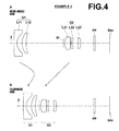
- FIG. 4 is a cross sectional diagram that illustrates the lens configuration of a zoom lens according to a fourth embodiment of the present invention.
- FIG. 5 is a cross sectional diagram that illustrates the lens configuration of a zoom lens according to a fifth embodiment of the present invention.
- FIG. 6 is a cross sectional diagram that illustrates the lens configuration of a zoom lens according to a sixth embodiment of the present invention.
- FIG. 7 is a cross sectional diagram that illustrates the lens configuration of a zoom lens according to a seventh embodiment of the present invention.
- FIG. 8 is a cross sectional diagram that illustrates the lens configuration of a zoom lens according to an eighth embodiment of the present invention.
- FIG. 9 A through H are graphs that illustrate various aberrations of the zoom lens of the first embodiment.
- FIG. 10 A through H are graphs that illustrate various aberrations of the zoom lens of the second embodiment.
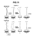
- FIG. 11 A through H are graphs that illustrate various aberrations of the zoom lens of the third embodiment.
- FIG. 12 A through H are graphs that illustrate various aberrations of the zoom lens of the fourth embodiment.
- FIG. 13 A through H are graphs that illustrate various aberrations of the zoom lens of the fifth embodiment.
- FIG. 14 A through H are graphs that illustrate various aberrations of the zoom lens of the sixth embodiment.
- FIG. 15 A through H are graphs that illustrate various aberrations of the zoom lens of the seventh embodiment.
- FIG. 16 A through H are graphs that illustrate various aberrations of the zoom lens of the eighth embodiment.
- FIG. 17 is a diagram that schematically illustrates an imaging apparatus according to an embodiment of the present invention.
- FIG. 1 is a cross sectional diagram that illustrates the configuration of a zoom lens according to an embodiment of the present invention, and corresponds to a zoom lens of Example 1 to be described later.
- FIG. 2 through FIG. 8 are cross sectional diagrams that illustrate configurations of zoom lenses according to other embodiments of the present invention, and corresponds to zoom lenses of Examples 2 through 8 to be described later.
- FIG. 1 through FIG. 8 The basic configurations of the embodiments illustrated in FIG. 1 through FIG. 8 are the same except that a second lens group G 2 is constituted by two lenses in the embodiment of FIG. 7 , and that the embodiment of FIG. 8 includes a third lens group G 3 .
- the manners in which the configurations are illustrated are also the same. Therefore, the zoom lenses according to the embodiments of the present invention will be described mainly with reference to FIG. 1 .
- the points in which the embodiments of FIGS. 7 and 8 differ from the other embodiments will be described in detail later.
- FIG. 1 the left side is the object side and the right side is the image side.
- a of FIG. 1 illustrates the arrangement of the optical system in a state focused on infinity at the wide angle end (shortest focal length state).
- B of FIG. 1 illustrates the arrangement of the optical system in a state focused on infinity at the telephoto end (longest focal length state). The same applies to FIGS. 2 through 8 to be described later.
- Each of the zoom lenses according to the embodiments of the present invention has a first lens group G 1 having a negative refractive power and a second lens group G 2 having a positive refractive power, in this order from the object side.
- An aperture stop St is included in the second lens group G 2 .
- the aperture stop St illustrated in the drawings does not necessarily represent the size or shape thereof, but only the position thereof on an optical axis Z.
- FIG. 1 illustrates an example in which a parallel plate optical member PP is provided between the second lens group G 2 and an imaging surface Sim.
- various filters such as a cover glass, an infrared ray cutoff filter, and a low pass filter, to be provided between the optical system and the imaging surface Sim, according to the configuration of a camera on which the lens is to be mounted.
- the optical member PP is provided assuming the presence of the cover glass, the various types of filters, and the like.
- recent imaging apparatuses employ the 3 CCD format, in which CCD's are employed for each color in order to improve image quality.
- a color separating optical system such as a color separating prism may be inserted between the lens system and the imaging surface Sim.
- a color separating optical system may be provided at the position of the optical member PP.
- This zoom lens is configured such that the distance between the first lens group G 1 and the second lens group G 2 changes when changing magnification. More specifically, the first lens group G 1 moves toward the imaging surface Sim along a convex trajectory, the second lens group G 2 moves monotonously toward the object side when changing magnification from the wide angle end to the telephoto end, and the aperture stop St moves integrally with the second lens group G 2 .
- the movement trajectories of the first lens group G 1 and the second lens group G 2 when changing magnification from the wide angle end to the telephoto end are schematically illustrated by the arrows between A and B of FIG. 1 .
- the first lens group G 1 is constituted by a first lens L 11 having a negative refractive power and a second lens L 12 having a positive refractive power, in this order from the object side.
- the first lens L 11 may be a biconcave lens and the second lens L 12 may be a positive meniscus lens, as illustrated in the example illustrated in FIG. 1 .
- the latter of the first lens L 11 and the second lens L 12 is a plastic lens. In the present embodiment, both of the lenses are plastic lenses.
- the second lens group G 2 is constituted by a third lens 21 having a positive refractive power, a fourth lens L 22 having a negative refractive power, and a fifth lens L 23 having a positive refractive power, in this order from the object side.
- the third lens L 21 may be a biconvex lens
- the fourth lens L 22 may be a biconcave lens
- the fifth lens L 23 may be a positive meniscus lens as in the example illustrated in FIG. 1 .
- all of the lenses L 21 , L 22 , and L 23 of the second lens group G 2 are plastic lenses.
- All of the lenses are plastic lenses except for the third lens L 21 of FIG. 3 , the first lens L 11 , the third lens L 21 , and the fourth lens L 22 of FIG. 4 , and the lens L 11 of FIG. 5 .
- the first lens group G 1 is constituted by the first lens L 11 and the second lens L 12 .
- At least the second lens L 12 is a plastic lens (more preferably, both of the lenses are plastic lenses).
- the zoom lens satisfies Conditional Formulae (1) through (4) to be described later, and further Conditional Formulae (2′), (3′), and (5). Therefore, a variable magnification ratio of approximately 3 ⁇ can be secured with a small number of lenses, while achieving cost reduction by the use of plastic lenses and realizing favorable optical performance.
- the configuration illustrated in FIG. 7 differs from the others in that the second lens group G 2 is constituted by two lenses, that is, the third lens L 21 and the fourth lens L 22 .
- the aforementioned operational advantageous effects can be obtained by this configuration as well.
- the configuration illustrated in FIG. 8 differs from the others in that a third lens group G 3 comprising one sixth lens L 31 is provided in addition to the first lens group G 1 and the second lens group G 2 .
- the sixth lens L 31 that constitutes the third lens group G 3 may be a biconvex lens as illustrated in FIG. 8 .
- the present zoom lens satisfies the following conditional formulae: 1.48 ⁇ Nd 1 n ⁇ 1.71 (1) 1.60 ⁇ Nd 1 p ⁇ 1.65 (2) 18 ⁇ d 1 p ⁇ 25 (3) 0.2 ⁇ d 2/ fw ⁇ 0.5 (4)
- Nd1n is the refractive index of the first lens L 11 with respect to the d line
- Nd1p and ⁇ d1p are the refractive index and the Abbe's number of the second lens L 12 with respect to the d line
- d2 is the spatial distance between the first lens L 11 and the second lens L 12 along the optical axis
- fw is the focal length of the entire system at the wide angle end.
- Table 25 examples of numerical values of each condition determined by the above Conditional Formulae (1) through (4) for each embodiment are shown in Table 25.
- Table 25 also shows examples of numerical values of each condition determined by Conditional Formula (5) to be described later.
- the present zoom lens also satisfies the following conditional formulae: 1.621 ⁇ Nd 1 p ⁇ 1.650 (2′) 18 ⁇ d 1 p ⁇ 24 (3′) 50 ⁇ Y ⁇ TL ⁇ 550 (5)
- Nd1p and ⁇ d1p are the refractive index and the Abbe's number of the positive lens (the second lens L 12 ) of the first lens group G 1 with respect to the d line, respectively
- Y is a maximum image height
- TL is the distance along the optical axis from the surface of the lens most toward the object side (the surface of the first lens L 11 toward the object side) in the first lens group G 1 to an imaging surface when the first lens group G 1 is positioned most toward the object side % refer to Table 25, the same applies hereinafter).
- the present zoom lens satisfies the following conditional formulae: 1.60 ⁇ Nd 2 n ⁇ 1.70 (6) 20.0 ⁇ d 2 n ⁇ 28.0 (7)
- Nd2n and ⁇ d2n are the refractive index and the Abbe's number of the negative lens (the fourth lens L 22 ) of the second lens group G 2 with respect to the d line, respectively.
- the zoom lens of the present example satisfies the following conditional formula: 0.5 ⁇ ( Rpr+Rpf )/( Rpr ⁇ Rpf ) ⁇ 6.2 (8)
- Rpf is the paraxial radius of curvature of the surface of the plastic lens (the second lens L 12 ) having the positive refractive power provided in the first lens group G 1 toward the object side
- Rpr is the paraxial radius of curvature of the surface of the plastic lens (the second lens L 12 ) having the positive refractive power provided in the first lens group G 1 toward the image side.
- the aforementioned paraxial radii of curvatures are the radii of curvature in the case that the surfaces of the lens approximate spherical surfaces.
- the present zoom lens satisfies the following conditional formula: 48 ⁇ d 1 n ⁇ 65 (9)
- ⁇ d1n is the Abbe's number of the negative lens (the first lens L 11 ) of the first lens group G 1 which is provided most toward the object side.
- the present zoom lens satisfies the following conditional formula: 0.45 ⁇ M 2/ ft ⁇ 0.75 (10)
- M2 is the a-mount of movement of the second lens group G 2 when changing magnification from the wide angle end to the telephoto end
- ft is the focal length of the entire system at the telephoto end.
- the present zoom lens satisfies the following conditional formula: 0.22 ⁇ d 12 t/d 2 gt ⁇ 0.60 (11)
- d12t is the spatial distance along the optical axis from the surface of a lens of the first lens group G 1 most toward the image side (the surface of the second lens L 12 toward the image side) to the surface of a lens of the second lens group G 2 most toward the object side (the surface of the third lens 21 toward the object side) when the zoom lens is focused on an object at infinity at the telephoto end
- d2gt is the distance along the optical axis from the surface of a lens of the second lens group G 2 most toward the object side to the surface of the lens of the second lens group G 2 most toward the image side (the surface of the fifth lens L 23 toward the image side).
- the present zoom lens satisfies the following conditional formula: 5.8 ⁇ TLw/fw ⁇ 8.4 (12)
- TLw is the distance from the surface of a lens most toward the object side in the first lens group G 1 (the surface of the first lens L 11 toward the object side) to an imaging surface Sim along the optical axis at the wide angle end
- fw is the focal length of the entire system at the wide angle end.
- the present zoom lens is provided with a positive lens (the third lens L 21 ) most toward the object side in the second lens group G 2 , and satisfies the following conditional formulae: 1.48 ⁇ Nd 2 p ⁇ 1.65 (13) 45 ⁇ d 2 p ⁇ 65 (14)
- Nd2p and ⁇ d2p are the refractive index and the Abbe's number of the third lens L 21 with respect to the d line, respectively.
- the negative lens (the first lens L 11 ) provided most toward the object side in the first lens group G 1 is an aspherical lens, and further, the first lens L 1 is a plastic lens in order to reduce cost.
- the plastic lens (the second lens L 12 ) having the positive refractive power provided in the first lens group G 1 is also an aspherical lens.
- the lens (the third lens L 21 ) provided most toward the object side in the second lens group G 2 is an aspherical lens, and further the third lens L 21 is a plastic lens in order to reduce cost.
- the lens (the fifth lens L 23 ) provided most toward the image side in the second lens group G 2 is an aspherical plastic lens in order to reduce cost.
- the present zoom lens is of a configuration, in which the entirety of the second lens group G 2 is moved along the optical axis when focusing from infinity to a near distance.
- the present invention is not limited, to this configuration, and only a portion of the lenses provided in the second lens group G 2 , for example, the fifth lens L 23 having the positive refractive power, may be moved along the optical axis.
- conditional formulae (1), (3), (5), (6), (8), and (9) are as follows: 1.48 ⁇ Nd 1 n ⁇ 1.70 (1′) 19 ⁇ d 1 p ⁇ 24 (3′′) 55 ⁇ Y ⁇ TL ⁇ 530 (5′) 1.60 ⁇ Nd 2 n ⁇ 1.69 (6′) 1.6 ⁇ ( Rpr+Rpf )/( Rpr ⁇ Rpf ) ⁇ 6.1 (8′) 50 ⁇ d 1 n ⁇ 65 (9′)
- the present zoom lens satisfies Conditional Formulae (1′), (3′′), (5′), (6′), (8′), and (9′).
- Conditional Formula (3′′) is more preferable than previously listed Conditional Formula (3′).
- Conditional Formula (1) determines the refractive index of the negative lens (the first lens L 11 ) provided most toward the object side in the first lens group G 1 .
- the positive lens (the second lens L 12 ) provided in the first lens group G 1 is constituted by a plastic material having the optical properties indicated by Conditional Formula (2) and Conditional Formula (3) and the value of Nd1n is greater than or equal to the upper limit defined in Conditional Formula (1), the power of the first lens L 11 , which is the negative lens provided most toward the object side in the first lens group G 1 , and the power of the second lens L 12 , which is the positive lens in the first lens group G 1 , will become great.
- the present zoom lens satisfies Conditional Formula (1′) within the range defined in Conditional Formula (1), and therefore the above advantageous effects are more prominent.
- Conditional Formula (2) determines the refractive index of the positive lens (the second lens L 12 ) formed by plastic provided in the first lens group G 1 . If the value of Nd1p is less than or equal to the lower limit defined in Conditional Formula (2), the radius of curvature (approximated radius of curvature) of the second lens will become great. As a result, the occurrence of various types of aberrations and lateral chromatic aberration will increase, which is not preferable. Inversely, if the value of Nd1p is greater than or equal to the upper limit defined in Conditional Formula (2), astigmatic aberration becomes great, which is not preferable. In addition, it becomes difficult to select a plastic material having favorable optical properties. The above shortcomings can be prevented in the case that Conditional Formula (2) is satisfied.
- Conditional Formula (3) determines the Abbe's number of the positive lens (the second lens L 12 ) formed by plastic provided in the first lens group G 1 . If the value of ⁇ d1p is less than or equal to the lower limit defined in Conditional Formula (3), it becomes difficult to correct longitudinal chromatic aberration and lateral chromatic aberration in a balanced manner, which is not preferable. Inversely, if the value of ⁇ d1p is greater than or equal to the upper limit defined in Conditional Formula (3), the difference in Abbe's numbers between the lens L 11 , which is the positive lens provided in the first lens group G 1 , and the negative lens provided in the first lens group G 1 decreases, and it will become necessary to increase the power of the lenses in order to correct chromatic aberrations. As a result, correction of spherical aberration and astigmatic aberration will become difficult, which is not preferable. The above shortcomings can be prevented in the case that Conditional Formula (3) is satisfied.
- the present zoom lens satisfies Conditional Formula (3′′) within the range defined in Conditional Formula (3), and therefore the above advantageous effects are more prominent.
- Conditional Formula (4) determines the relationship between the spatial distance between the negative lens and the positive lens of the first lens group G 1 , that is, the first lens L 11 and the second lens L 12 , and the focal length of the entire system at the wide angle end. If the value of d2/fw is less than or equal to the lower limit defined in Conditional Formula (4), such a small distance is advantageous from the viewpoint of miniaturization, but is not preferable because correction of spherical aberration will became difficult. Inversely, if the value of d2/fw is greater than or equal to the upper limit defined in Conditional formula (4), the first lens group G 1 will become large as a whole, which is not preferable. The above shortcomings can be prevented in the case that Conditional Formula (4) is satisfied.
- the present zoom lens is configured to satisfy Conditional Formulae (2′), (3′), and (5) when Nd1p and ⁇ d1p are the refractive index and the Abbe's number of the second lens with respect to the d line, respectively, Y is a maximum image height, and TL is the distance along an optical axis when the first lens group is positioned most toward the object side. Therefore, a variable magnification ratio of approximately 3 ⁇ can be secured with a small number of lenses, while achieving cost reduction by the use of plastic lenses, and realizing favorable optical performance.
- Conditional Formula (5) determines the product of the maximum image height and the total length of the optical system. If the value of Y ⁇ TL is greater than or equal to the upper limit defined in Conditional Formula (5), the size of a compact camera will increase, which is not preferable from the viewpoint of portability. Inversely, if the value of Y ⁇ TL is less than or equal to the lower limit defined in Conditional Formula (5), the zoom lens will become extremely compact, but the number of pixels of imaging elements that can be applied will decrease. Alternatively, if the number of pixels is maintained the same, the pixel size is decreased. In either case, image quality will deteriorate, which is not preferable. The above shortcomings can be prevented in the case that Conditional Formula (5) is satisfied.
- the first lens group G 1 of the present zoom lens is constituted only by the first lens L 11 having the negative refractive power and the second lens 12 having the positive refractive power, provided in this order from the object size. Therefore, the number of lenses can be suppressed, and further cost reductions can be realized.
- Conditional Formula (6) determines the refractive index of the negative lens (the fourth lens L 22 ) provided in the second lens group. If the value of Nd2n is outside the range defined in Conditional Formula (6), it will become difficult to correct spherical aberrations and astigmatic aberrations in a balanced manner, which is not preferable. The above shortcomings can be prevented in the case that Conditional Formula (6) is satisfied.
- Conditional Formula (7) determines the Abbe's number of the negative lens (the fourth lens L 22 ) provided in the second lens group. If the value of ⁇ d2n is outside the range defined in Conditional Formula (7), it will become difficult to correct longitudinal chromatic aberrations and lateral chromatic aberrations in a balanced manner within all zoom regions. The above shortcomings can be prevented in the case that Conditional Formula (7) is satisfied.
- the present zoom lens realizes further cost reductions because the second lens group G 2 comprises only one negative lens (the fourth lens L 22 ), and the negative lens is a plastic lens.
- Conditional Formula (8) determines the shape factor of the plastic lens (the second lens L 12 ) having the positive refractive power provided in the first lens group G 1 . If the value of (Rpr+Rpf)/(Rpr ⁇ Rpf) is less than or equal to the lower limit defined in Conditional Formula (8), the powers of the negative lens and the positive lens provided in the first lens group G 1 , that is, the first lens L 11 and the second lens L 12 , will become great. As a result, it will become difficult to correct spherical aberrations and coma aberrations in a balanced manner.
- the present zoom lens satisfies Conditional Formula (8′) within the range defined in Conditional Formula (8), and therefore the above advantageous effects are more prominent.
- the second lens group G 2 is constituted by two positive lenses (the third lens L 21 and the fifth lens L 23 ) and one negative lens (the fourth lens L 22 ). Therefore, the advantageous effects related to cost reduction are more prominent.
- the advantageous effects related to cost reduction will also become more prominent in the case that the zoom lens of the present invention practically comprises only the first lens group and the second lens group.
- the present zoom lens satisfies Conditional Formula (10), and therefore the following advantageous effects can be obtained. That is, if the value of M2/ft is less that or equal to the lower limit defined in Conditional Formula (10), it will become difficult to increase the variable magnification ratio. In addition, it will become necessary to increase the power of the second lens group G 2 , resulting in the tolerances for production error and assembly error becoming small, which is not preferable. Inversely, if the value of M2/ft is greater than or equal to the upper limit defined in Conditional Formula (10), the amount of movement of the second lens group G 2 will become great, and the lens system will become large, which is not preferable. The above shortcomings can be prevented in the case that Conditional Formula (10) is satisfied.
- the present zoom lens satisfies Conditional Formula (11), and therefore the following advantageous effects can be obtained. That is, if the value of d12t/d2gt is less that or equal to the lower limit defined in Conditional Formula (11), it will become difficult to avoid interference among the lenses that constitute the first lens group G 1 and the second lens group G 2 , lens holding members, and the like, which is not preferable. Inversely, if the value of d12t/d2gt is greater than or equal to the upper limit defined in Conditional Formula (11), it will become difficult to obtain a desired variable magnification ratio while suppressing the total length of the optical system, which is not preferable. The above shortcomings can be prevented in the case that Conditional Formula (11) is satisfied.
- the preset zoom lens satisfies Conditional Formula (12), and therefore the following advantageous effects can be obtained. That is, if the value of TLw/fw is less than or equal to the lower limit defined in Conditional Formula (12), the zoom lens can be configured to be compact. However, the power of each lens will become great, resulting in correction of aberrations becoming difficult. In addition, the tolerances for production error and assembly error will become small, which is not preferable. If the value of TLw/fw is greater than or equal to the upper limit defined in Conditional Formula (12), the total length of the optical system will become great, which is not preferable. The above shortcomings can be prevented in the case that Conditional Formula (12) is satisfied.
- the present zoom lens satisfies Conditional Formulae (13) and (14), and therefore the following advantageous effects can be obtained. That is, if the value of Nd2p is less than or equal to the lower limit defined in Conditional Formula (13), the radius of curvature (approximated radius of curvature) of the second lens will become great. As a result, the central thickness will become great in order to secure a necessary flange (edge thickness), the second lens group G 2 will become large, and the occurrence of various aberrations will increase, which is not preferable.
- the entire lens system is constituted by five lenses or less, and all of the lenses of the lens system are plastic lenses. Therefore, the advantageous effects related to cost reduction will be more prominent.
- the second lens group G 2 is constituted by only one positive lens and one negative lens (the third lens L 21 and the fourth lens L 22 ), and both of these lenses are plastic lenses. Therefore, the advantageous effects related to cost reduction will be more prominent.
- the present zoom lens is of a configuration, in which the entirety of the second lens group is moved along the optical axis when focusing from infinity to a near distance. Therefore, the following advantageous effects can be obtained. That is, in the zoom type lens employed in the present invention, it is possible to obtain favorable optical performance regardless of whether the entirety of the first lens group G 1 , the entirety of the second lens group G 2 , or a portion of the lenses of the second lens group G 2 , is selected as the lenses to be moved during focusing operations. However, in the case that a configuration in which the entirety of the first lens group G 1 is moved forward to focus, the effective diameter of the first lens group G 1 will become large and it will become necessary to move lenses having large outer diameters. However, such problems can be avoided in the case that a configuration is adopted, in which the entirety of the second lens group G 2 or a portion of the lenses of the second lens group G 2 are moved to perform focusing operations.
- FIG. 1 illustrates an example in which the optical member PP is provided between the lens system and the imaging surface.
- various filters such as low pass filters and filters that cut off specific wavelength bands may be provided among each of the lenses.
- coatings that have the same functions as the various filters may be administered on the surfaces of the lenses.
- the item ⁇ dj represents the Abbe's number of the jth constituent element with respect to the d line.
- the aperture stop St is also included in the basic lens data, and the radius of curvature of the surface corresponding to the aperture stop St is shown as “ ” (aperture stop).
- D4 and D11 in the basic lens data of Table 1 represents the distances between surfaces that change when changing magnification.
- D4 is the distance between the first lens group G 1 and the second lens group G 2
- D11 is the distance between the second lens group G 2 and the optical member PP.
- D9 is employed instead of D11.
- the data of Table 2 related to zoom shows values of the focal length (f), the F value (Fno.), and the full angle of view (2 ⁇ ) of the entire system and the distances among surfaces that change at the wide angle end and at the telephoto end.
- Zd is the depth of the aspherical surface (the length of a normal line that extends from a point on the aspherical surface having a height h to a plane perpendicular to the optical axis that contacts the peak of the aspherical surface)
- h is the height (the distance from the optical axis to the surface of the lens)
- C is the inverse of the paraxial radius of curvature
- the tables below show numerical values which are rounded off at a predetermined number of digits.
- degrees are used as the units for angles and mm are used as the units for lengths in the data of the tables below.
- optical systems it is possible for optical systems to be proportionately enlarged or proportionately reduced and utilized. Therefore, other appropriate units may be used.
- Example 1 Basic Lens Data Si Ri Ndj ⁇ dj (Surface (Radius of Di (Refractive (Abbe's Number) Curvature) (Distance) Index) Number) *1 ⁇ 45.7782 1.50 1.53389 56.0 *2 5.6000 2.60 3 9.3453 2.00 1.63355 23.6 *4 15.9288 D4 5 ⁇ (aperture stop) 0.40 *6 7.6622 2.80 1.53389 56.0 7 ⁇ 11.1702 0.23 *8 ⁇ 93.6000 0.80 1.63355 23.6 *9 10.0000 2.76 *10 ⁇ 14.0449 1.30 1.53389 56.0 *11 ⁇ 7.5692 D11 12 ⁇ 0.80 1.51680 64.2 13 ⁇ 6.81 *Aspherical Surface
- Example 1 Aspherical Surface Coefficients Surface Number 1 2 4 KA ⁇ 7.1226025 0.6195752 0.0455753 RA3 2.8527533E ⁇ 03 1.3047539E ⁇ 03 8.2616248E ⁇ 05 RA4 ⁇ 4.1473757E ⁇ 04 1.9281865E ⁇ 03 ⁇ 6.5096304E ⁇ 04 RA5 1.1199128E ⁇ 04 ⁇ 1.1017867E ⁇ 03 3.9845953E ⁇ 04 RA6 2.3620192E ⁇ 05 4.1238273E ⁇ 04 ⁇ 1.2520730E ⁇ 04 RA7 ⁇ 1.2231466E ⁇ 05 ⁇ 6.2883982E ⁇ 05 4.5479129E ⁇ 06 RA8 ⁇ 1.5116175E ⁇ 06 ⁇ 2.2860711E ⁇ 06 3.9213839E ⁇ 06 RA9 6.9957609E ⁇ 07 7.0291982E ⁇ 07 ⁇ 2.3604960E ⁇ 07 RA10 1.7009286E ⁇ 08 7.4810093E ⁇ 08 ⁇ 5.0184152E ⁇ 08 RA
- Example 2 Aspherical Surface Coefficients Surface Number 1 2 3 KA ⁇ 7.1446350 0.7117550 0.0493759 RA3 1.6022406E ⁇ 02 1.2449006E ⁇ 02 ⁇ 1.7913828E ⁇ 03 RA4 ⁇ 2.8230074E ⁇ 03 1.1832579E ⁇ 02 ⁇ 4.0043994E ⁇ 03 RA5 7.9442811E ⁇ 04 ⁇ 9.0809084E ⁇ 03 2.8944886E ⁇ 03 RA6 3.4187424E ⁇ 04 6.0446252E ⁇ 03 ⁇ 1.8472108E ⁇ 03 RA7 ⁇ 3.3809595E ⁇ 04 ⁇ 1.6385012E ⁇ 03 1.2829162E ⁇ 04 RA8 ⁇ 6.5570814E ⁇ 05 ⁇ 9.9309361E ⁇ 05 1.7000076E ⁇ 04 RA9 5.4086217E ⁇ 05 5.0384035E ⁇ 05 ⁇ 1.5692174E ⁇ 05 RA10 2.2388992E ⁇ 06 9.4466499E ⁇ 06 ⁇ 6.3
- Example 3 Aspherical Surface Coefficients Surface Number 1 2 4 KA 0.4265106 1.1005323 ⁇ 0.3047225 RA3 1.0032316E ⁇ 03 3.3994625E ⁇ 04 2.6383815E ⁇ 04 RA4 ⁇ 8.1057546E ⁇ 05 4.8599520E ⁇ 04 ⁇ 3.3692057E ⁇ 04 RA5 2.5042680E ⁇ 05 ⁇ 1.6109963E ⁇ 04 1.0014716E ⁇ 04 RA6 2.9921605E ⁇ 06 4.4035348E ⁇ 05 ⁇ 1.4124732E ⁇ 05 RA7 ⁇ 1.1149005E ⁇ 06 ⁇ 5.1375038E ⁇ 06 ⁇ 1.1167345E ⁇ 07 RA8 ⁇ 7.2929416E ⁇ 08 ⁇ 1.0636232E ⁇ 07 1.7826466E ⁇ 07 RA9 2.0758191E ⁇ 08 2.4173644E ⁇ 08 ⁇ 1.2396842E ⁇ 09 RA10 4.7212173E ⁇ 10 1.3201382E ⁇ 09 ⁇ 8.0134068E ⁇ 10 RA
- Example 5 Aspherical Surface Coefficients Surface Number 1 2 3 KA 5.5505612 1.0608379 0.2649910 RA3 4.2497242E ⁇ 03 4.3032982E ⁇ 03 7.4737823E ⁇ 04 RA4 ⁇ 4.4717766E ⁇ 03 ⁇ 4.4097098E ⁇ 03 ⁇ 1.8709297E ⁇ 03 RA5 2.5765441E ⁇ 03 2.8302594E ⁇ 04 2.2256072E ⁇ 04 RA6 ⁇ 3.3743127E ⁇ 04 1.4302833E ⁇ 03 4.9060799E ⁇ 05 RA7 ⁇ 4.6973970E ⁇ 05 ⁇ 4.5466316E ⁇ 04 2.7685188E ⁇ 06 RA8 ⁇ 6.5368423E ⁇ 06 ⁇ 1.0119830E ⁇ 05 1.8316374E ⁇ 06 RA9 5.5602495E ⁇ 06 1.1176599E ⁇ 05 ⁇ 6.7417456E ⁇ 07 RA10 1.5755642E ⁇ 07 8.0327374E ⁇ 07 ⁇ 2.1205117E ⁇ 08 RA11
- Example 7 Basic Lens Data Si Ndj ⁇ dj (Surface Ri Di (Refractive (Abbe's Number) (Radius of Curvature) (Distance) Index) Number) *1 ⁇ 22.4371 1.10 1.49023 57.5 *2 6.5700 2.29 *3 6.8084 1.67 1.63355 23.6 *4 9.7661 D4 5 ⁇ (aperture stop) 0.40 *6 5.6000 3.20 1.49023 57.5 7 ⁇ 7.8503 0.32 *8 ⁇ 6.2454 1.20 1.63355 23.6 *9 ⁇ 19.3121 D9 10 ⁇ 0.80 1.51680 64.2 11 ⁇ 7.43 *Aspherical Surface
- Example 7 Aspherical Surface Coefficients Surface Number 1 2 3 4 KA ⁇ 9.7780633 ⁇ 0.4996645 ⁇ 1.3403884 ⁇ 0.9413769 RA3 ⁇ 3.4287750E ⁇ 03 ⁇ 5.9826274E ⁇ 03 ⁇ 1.6143319E ⁇ 03 ⁇ 6.9413781E ⁇ 05 RA4 4.0029165E ⁇ 03 6.0064687E ⁇ 03 5.0451395E ⁇ 04 ⁇ 1.4215029E ⁇ 03 RA5 ⁇ 8.5764331E ⁇ 04 ⁇ 1.5230887E ⁇ 03 ⁇ 3.4183912E ⁇ 04 4.5928562E ⁇ 04 RA6 8.2086269E ⁇ 05 1.9098931E ⁇ 04 1.1146784E ⁇ 04 ⁇ 3.7661431E ⁇ 05 RA7 ⁇ 3.4960467E ⁇ 08 1.7027340E ⁇ 05 ⁇ 1.1830129E ⁇ 05 ⁇ 2.6559468E ⁇ 05 RA8 ⁇ 6.9980109E ⁇ 07 ⁇ 1.0766751E ⁇ 06 ⁇
- Example 8 Basic Lens Data Si Ri ⁇ dj (Surface (Radius Di Ndj (Abbe's Number) of Curvature) (Distance) (Refractive Index) Number) *1 ⁇ 38.0636 1.50 1.53389 56.0 *2 5.6000 2.60 3 9.0413 2.20 1.63355 23.6 *4 15.8402 D4 5 ⁇ (aperture stop) 0.40 *6 7.6194 2.80 1.53389 56.0 7 ⁇ 10.1927 0.23 *8 ⁇ 85.4094 0.83 1.63355 23.6 *9 10.0000 2.92 *10 ⁇ 12.2543 1.30 1.53389 56.0 *11 ⁇ 7.8625 D11 12 70.0000 1.50 1.53389 56.0 13 ⁇ 70.0000 2.00 14 ⁇ 0.80 1.51680 64.2 15 ⁇ 3.01 *Aspherical Surface
- Example 8 Aspherical Surface Coefficients Surface Number 1 2 4 KA ⁇ 7.1164362 0.6720648 0.0379012 RA3 2.6929571E ⁇ 03 9.6824859E ⁇ 04 1.7923203E ⁇ 04 RA4 ⁇ 4.1477171E ⁇ 04 1.8887758E ⁇ 03 ⁇ 6.4318302E ⁇ 04 RA5 1.1209763E ⁇ 04 ⁇ 1.1313039E ⁇ 03 4.1339259E ⁇ 04 RA6 2.3721969E ⁇ 05 4.1219549E ⁇ 04 ⁇ 1.2542582E ⁇ 04 RA7 ⁇ 1.2190763E ⁇ 05 ⁇ 6.2870121E ⁇ 05 4.4722605E ⁇ 06 RA8 ⁇ 1.5106780E ⁇ 06 ⁇ 2.2817305E ⁇ 06 3.9266356E ⁇ 06 RA9 7.0067013E ⁇ 07 7.1253827E ⁇ 07 ⁇ 2.3023798E ⁇ 07 RA10 1.7288758E ⁇ 08 7.4891059E ⁇ 08 ⁇ 4.9930149E ⁇
- Example 2 Example 3
- Example 4 Example 5
- Example 6 Example 7
- Example 8 (1) Nd1n 1.534 1.490 1.534 1.694 1.619 1.534 1.490 1.534 (2)
- the spherical aberration, the astigmatic aberration, the distortion, and the lateral chromatic aberration of the zoom lens of Example 1 at the wide angle end are illustrated in A through D of FIG. 9 , respectively.
- the spherical aberration, the astigmatic aberration, the distortion, and the lateral chromatic aberration of the zoom lens of Example 1 at the telephoto end are illustrated in E through H of FIG. 9 , respectively.
- each of the diagrams that illustrate the aberrations use the d line (wavelength: 587.6 nm) as a standard. However, in the diagrams that illustrate spherical aberration, aberrations related to wavelengths of 460.0 nm and 615.0 nm are also shown. In addition, the diagrams that illustrate lateral chromatic aberration also show aberrations related to wavelengths of 460.0 nm and 615.0 nm. In the diagrams that illustrate astigmatic aberrations, aberrations in the sagittal direction are indicated by solid lines, while aberrations in the tangential direction are indicated by broken lines. In the diagrams that illustrate spherical aberrations, “Fno.” denotes F values. In the other diagrams that illustrate the aberrations, ⁇ denotes half angles of view.
- the aberrations of the zoom lens of Example 2 are illustrated in A through H of FIG. 10 .
- the aberrations of the zoom lenses of Examples 3 through 11 are illustrated in FIG. 11 through FIG. 16 .
- FIG. 17 is a diagram that schematically illustrates an imaging apparatus 10 according to the embodiment of the present invention that employs the zoom lens 1 of the embodiment of the present invention.
- the imaging apparatus may be a surveillance camera, a video camera, an electronic still camera, or the like.
- the imaging apparatus 10 illustrated in FIG. 17 is equipped with: the zoom lens 1 ; an imaging element 2 that captures images of subjects focused by the zoom lens 1 , provided toward the image side of the zoom lens 1 ; a signal processing section 4 that processes signals output from the imaging element 2 ; a magnification control section 5 that changes the magnification of the zoom lens 1 ; and a focus control section 6 that performs focus adjustments. Note that various filters and the like may be provided between the zoom lens 1 and the imaging element 2 as appropriate.
- the zoom lens 1 has the first lens group G 1 having a negative refractive power and the second lens group G 2 having a positive refractive power.
- the zoom lens 1 is configured to change magnification by changing the distance between the first lens group G 1 and the second lens group G 2 .
- the first lens group G 1 is constituted by two lenses, the first lens L 11 having a negative refractive power and the second lens L 12 having a positive refractive power. Both of the lenses L 1 and L 12 are plastic lenses.
- the imaging element 2 captures an optical image formed by the zoom lens 1 and outputs electrical signals.
- the imaging surface thereof is provided to match the imaging plane of the zoom lens 1 .
- a CCD, a CMOS, or the like may be employed as the imaging element 2 .
- the imaging apparatus 10 may be further equipped with a blur correcting mechanism that moves a lens having a positive refractive power that constitutes a portion of the second lens group G 2 in a direction perpendicular to the optical axis Z in order to correct blurring of obtained images due to vibration or shaky hands.
- the present invention has been described with reference to the embodiments and Examples thereof. However, the present invention is not limited to the embodiments and Examples described above, and various modifications are possible.
- the values of the radii of curvature, the distances among surfaces, the refractive indices, the Abbe's numbers, the aspherical surface coefficients, etc. are not limited to the numerical values indicated in connection with the Examples, and may be other values.
Landscapes
- Physics & Mathematics (AREA)
- General Physics & Mathematics (AREA)
- Optics & Photonics (AREA)
- Nonlinear Science (AREA)
- Lenses (AREA)
Applications Claiming Priority (4)
| Application Number | Priority Date | Filing Date | Title |
|---|---|---|---|
| JP140026/2011 | 2011-06-24 | ||
| JP2011-140026 | 2011-06-24 | ||
| JP2011140026 | 2011-06-24 | ||
| PCT/JP2012/003693 WO2012176389A1 (ja) | 2011-06-24 | 2012-06-06 | ズームレンズおよび撮像装置 |
Related Parent Applications (1)
| Application Number | Title | Priority Date | Filing Date |
|---|---|---|---|
| PCT/JP2012/003693 Continuation WO2012176389A1 (ja) | 2011-06-24 | 2012-06-06 | ズームレンズおよび撮像装置 |
Publications (2)
| Publication Number | Publication Date |
|---|---|
| US20140092485A1 US20140092485A1 (en) | 2014-04-03 |
| US9007697B2 true US9007697B2 (en) | 2015-04-14 |
Family
ID=47422252
Family Applications (1)
| Application Number | Title | Priority Date | Filing Date |
|---|---|---|---|
| US14/100,036 Expired - Fee Related US9007697B2 (en) | 2011-06-24 | 2013-12-09 | Zoom lens and imaging apparatus |
Country Status (4)
| Country | Link |
|---|---|
| US (1) | US9007697B2 (ja) |
| JP (1) | JP5905883B2 (ja) |
| CN (1) | CN103620470B (ja) |
| WO (1) | WO2012176389A1 (ja) |
Families Citing this family (4)
| Publication number | Priority date | Publication date | Assignee | Title |
|---|---|---|---|---|
| CN103620471B (zh) * | 2011-06-24 | 2016-08-31 | 富士胶片株式会社 | 变焦镜头和成像设备 |
| JP6422231B2 (ja) * | 2013-04-25 | 2018-11-14 | キヤノン株式会社 | ズームレンズ及びそれを有する撮像装置 |
| CN105589182B (zh) | 2014-10-24 | 2018-02-02 | 玉晶光电(厦门)有限公司 | 光学成像镜头及应用此镜头的电子装置 |
| CN115308890B (zh) * | 2022-10-12 | 2022-12-20 | 昆明全波红外科技有限公司 | 一种紧凑型长波手动变焦红外镜头 |
Citations (23)
| Publication number | Priority date | Publication date | Assignee | Title |
|---|---|---|---|---|
| US20050200970A1 (en) | 2004-03-11 | 2005-09-15 | Konica Minolta Photo Imaging, Inc. | Image-taking apparatus |
| JP2006039182A (ja) | 2004-07-27 | 2006-02-09 | Konica Minolta Photo Imaging Inc | 撮像装置 |
| JP2007025373A (ja) | 2005-07-19 | 2007-02-01 | Matsushita Electric Ind Co Ltd | 変倍レンズ光学系、並びにそれを用いた撮像光学機器及び携帯型情報端末機器 |
| US20070121215A1 (en) | 2005-11-30 | 2007-05-31 | Canon Kabushiki Kaisha | Zoom lens system and image-pickup apparatus including same |
| US20070171544A1 (en) | 2006-01-19 | 2007-07-26 | Fujinon Corporation | Variable-power imaging optical system and imaging device |
| JP2007187740A (ja) | 2006-01-11 | 2007-07-26 | Largan Precision Co Ltd | ズームレンズ |
| JP2008058600A (ja) | 2006-08-31 | 2008-03-13 | Canon Inc | ズームレンズ及びそれを有する撮像装置 |
| US20080158690A1 (en) | 2006-12-28 | 2008-07-03 | Pentax Corporation | Standard zoom lens system |
| JP2008257179A (ja) | 2007-03-12 | 2008-10-23 | Olympus Imaging Corp | 結像光学系及びそれを有する電子撮像装置 |
| JP2010091948A (ja) | 2008-10-10 | 2010-04-22 | Olympus Imaging Corp | ズームレンズ及びそれを備えた撮像装置 |
| US20110096407A1 (en) | 2009-10-27 | 2011-04-28 | Sony Corporation | Zoom lens and image pickup device |
| JP2011095328A (ja) | 2009-10-27 | 2011-05-12 | Sony Corp | ズームレンズ及び撮像装置 |
| US20120044577A1 (en) | 2010-08-20 | 2012-02-23 | Sony Corporation | Zoom lens and imaging apparatus |
| US20120050886A1 (en) | 2010-08-31 | 2012-03-01 | Nikon Corporation | Zoom lens, optical apparatus and zoom lens manufacturing method |
| US20120050884A1 (en) | 2010-08-31 | 2012-03-01 | Nikon Corporation | Zoom lens, optical apparatus and method for manufacturing zoom lens |
| JP2012053223A (ja) | 2010-08-31 | 2012-03-15 | Nikon Corp | ズームレンズ、光学機器及びズームレンズの製造方法 |
| US20120069451A1 (en) | 2010-09-21 | 2012-03-22 | Hoya Corporation | Zoom lens system and electronic imaging apparatus |
| US20120113312A1 (en) | 2010-11-09 | 2012-05-10 | Tetsuya Yanai | Zoom Lens and Image Pickup Apparatus Equipped with Same |
| JP2012098459A (ja) | 2010-11-01 | 2012-05-24 | Hoya Corp | ズームレンズ系及びこれを用いた電子撮像装置 |
| JP2012103675A (ja) | 2010-10-15 | 2012-05-31 | Nikon Corp | ズームレンズ、光学機器、およびズームレンズの製造方法 |
| JP2012103416A (ja) | 2010-11-09 | 2012-05-31 | Olympus Imaging Corp | ズームレンズ及びそれを用いた撮像装置 |
| US20140111870A1 (en) * | 2011-06-24 | 2014-04-24 | Fujifilm Corporation | Zoom lens and imaging apparatus |
| US20140111869A1 (en) * | 2011-06-24 | 2014-04-24 | Fujifilm Corporation | Zoom lens and imaging apparatus |
Family Cites Families (4)
| Publication number | Priority date | Publication date | Assignee | Title |
|---|---|---|---|---|
| JP5558254B2 (ja) * | 2010-08-02 | 2014-07-23 | オリンパスイメージング株式会社 | 光学装置 |
| JP2012226019A (ja) * | 2011-04-15 | 2012-11-15 | Olympus Imaging Corp | ズームレンズおよびそれを用いた撮像装置 |
| JP2012108279A (ja) * | 2010-11-17 | 2012-06-07 | Olympus Imaging Corp | 光路折り曲げ部材を有するズームレンズ及びそれを備える撮像装置 |
| JP5551055B2 (ja) * | 2010-12-08 | 2014-07-16 | Hoya株式会社 | ズームレンズ系 |
-
2012
- 2012-06-06 WO PCT/JP2012/003693 patent/WO2012176389A1/ja not_active Ceased
- 2012-06-06 CN CN201280031196.XA patent/CN103620470B/zh not_active Expired - Fee Related
- 2012-06-06 JP JP2013521425A patent/JP5905883B2/ja not_active Expired - Fee Related
-
2013
- 2013-12-09 US US14/100,036 patent/US9007697B2/en not_active Expired - Fee Related
Patent Citations (31)
| Publication number | Priority date | Publication date | Assignee | Title |
|---|---|---|---|---|
| JP2005258067A (ja) | 2004-03-11 | 2005-09-22 | Konica Minolta Photo Imaging Inc | 撮像装置 |
| US20050200970A1 (en) | 2004-03-11 | 2005-09-15 | Konica Minolta Photo Imaging, Inc. | Image-taking apparatus |
| JP2006039182A (ja) | 2004-07-27 | 2006-02-09 | Konica Minolta Photo Imaging Inc | 撮像装置 |
| JP2007025373A (ja) | 2005-07-19 | 2007-02-01 | Matsushita Electric Ind Co Ltd | 変倍レンズ光学系、並びにそれを用いた撮像光学機器及び携帯型情報端末機器 |
| US20070121215A1 (en) | 2005-11-30 | 2007-05-31 | Canon Kabushiki Kaisha | Zoom lens system and image-pickup apparatus including same |
| JP2007155836A (ja) | 2005-11-30 | 2007-06-21 | Canon Inc | ズームレンズ及びそれを有する撮像装置 |
| JP2007187740A (ja) | 2006-01-11 | 2007-07-26 | Largan Precision Co Ltd | ズームレンズ |
| US20070171544A1 (en) | 2006-01-19 | 2007-07-26 | Fujinon Corporation | Variable-power imaging optical system and imaging device |
| JP2007193140A (ja) | 2006-01-19 | 2007-08-02 | Fujinon Corp | 結像変倍光学系およびこれを用いた撮像装置 |
| JP2008058600A (ja) | 2006-08-31 | 2008-03-13 | Canon Inc | ズームレンズ及びそれを有する撮像装置 |
| US20090009883A1 (en) | 2006-08-31 | 2009-01-08 | Canon Kabushiki Kaisha | Zoom lens and image pickup apparatus having the same |
| US20080158690A1 (en) | 2006-12-28 | 2008-07-03 | Pentax Corporation | Standard zoom lens system |
| JP2008181118A (ja) | 2006-12-28 | 2008-08-07 | Hoya Corp | 標準ズームレンズ系 |
| JP2008257179A (ja) | 2007-03-12 | 2008-10-23 | Olympus Imaging Corp | 結像光学系及びそれを有する電子撮像装置 |
| JP2010091948A (ja) | 2008-10-10 | 2010-04-22 | Olympus Imaging Corp | ズームレンズ及びそれを備えた撮像装置 |
| US20110096407A1 (en) | 2009-10-27 | 2011-04-28 | Sony Corporation | Zoom lens and image pickup device |
| JP2011095328A (ja) | 2009-10-27 | 2011-05-12 | Sony Corp | ズームレンズ及び撮像装置 |
| US20120044577A1 (en) | 2010-08-20 | 2012-02-23 | Sony Corporation | Zoom lens and imaging apparatus |
| JP2012042811A (ja) | 2010-08-20 | 2012-03-01 | Sony Corp | ズームレンズ及び撮像装置 |
| US20120050886A1 (en) | 2010-08-31 | 2012-03-01 | Nikon Corporation | Zoom lens, optical apparatus and zoom lens manufacturing method |
| US20120050884A1 (en) | 2010-08-31 | 2012-03-01 | Nikon Corporation | Zoom lens, optical apparatus and method for manufacturing zoom lens |
| JP2012053223A (ja) | 2010-08-31 | 2012-03-15 | Nikon Corp | ズームレンズ、光学機器及びズームレンズの製造方法 |
| JP2012053222A (ja) | 2010-08-31 | 2012-03-15 | Nikon Corp | ズームレンズ、光学機器及びズームレンズの製造方法 |
| US20120069451A1 (en) | 2010-09-21 | 2012-03-22 | Hoya Corporation | Zoom lens system and electronic imaging apparatus |
| JP2012068327A (ja) | 2010-09-21 | 2012-04-05 | Hoya Corp | ズームレンズ系及びこれを用いた電子撮像装置 |
| JP2012103675A (ja) | 2010-10-15 | 2012-05-31 | Nikon Corp | ズームレンズ、光学機器、およびズームレンズの製造方法 |
| JP2012098459A (ja) | 2010-11-01 | 2012-05-24 | Hoya Corp | ズームレンズ系及びこれを用いた電子撮像装置 |
| US20120113312A1 (en) | 2010-11-09 | 2012-05-10 | Tetsuya Yanai | Zoom Lens and Image Pickup Apparatus Equipped with Same |
| JP2012103416A (ja) | 2010-11-09 | 2012-05-31 | Olympus Imaging Corp | ズームレンズ及びそれを用いた撮像装置 |
| US20140111870A1 (en) * | 2011-06-24 | 2014-04-24 | Fujifilm Corporation | Zoom lens and imaging apparatus |
| US20140111869A1 (en) * | 2011-06-24 | 2014-04-24 | Fujifilm Corporation | Zoom lens and imaging apparatus |
Non-Patent Citations (2)
| Title |
|---|
| International Search Report PCT/JP2012/003693 dated Oct. 2, 2012, with English Translation. |
| NPL International Preliminary Report on Patentability (PCT/IB/373) prepared for PCT/JP2012/003693 on Dec. 24, 2013. * |
Also Published As
| Publication number | Publication date |
|---|---|
| CN103620470A (zh) | 2014-03-05 |
| CN103620470B (zh) | 2015-12-09 |
| US20140092485A1 (en) | 2014-04-03 |
| JP5905883B2 (ja) | 2016-04-20 |
| WO2012176389A1 (ja) | 2012-12-27 |
| JPWO2012176389A1 (ja) | 2015-02-23 |
Similar Documents
| Publication | Publication Date | Title |
|---|---|---|
| US9535239B2 (en) | Zoom lens and imaging apparatus | |
| US9001433B2 (en) | Zoom lens and imaging apparatus | |
| US9323033B2 (en) | Zoom lens and imaging apparatus | |
| US11243384B2 (en) | Zoom lens and image pickup apparatus including the same | |
| US20150160444A1 (en) | Zoom lens and imaging apparatus | |
| US9261684B2 (en) | Zoom lens and imaging apparatus | |
| US9746667B2 (en) | Zoom lens and imaging apparatus | |
| US8917454B2 (en) | Zoom lens and imaging apparatus | |
| US8830593B2 (en) | Zoom lens and imaging apparatus | |
| US9025255B2 (en) | Zoom lens and imaging apparatus | |
| US9063322B2 (en) | Zoom lens and imaging apparatus | |
| US9235035B2 (en) | Zoom lens and imaging apparatus | |
| US9007697B2 (en) | Zoom lens and imaging apparatus | |
| US11294158B2 (en) | Zoom lens and imaging apparatus | |
| US20140153107A1 (en) | Zoom lens and imaging apparatus | |
| US20140168790A1 (en) | Zoom lens and imaging apparatus | |
| US9013804B2 (en) | Zoom lens and imaging apparatus | |
| US9007698B2 (en) | Zoom lens and imaging apparatus | |
| US20140177070A1 (en) | Zoom lens and imaging apparatus | |
| US9217850B2 (en) | Zoom lens and imaging apparatus | |
| US9013800B2 (en) | Zoom lens and imaging apparatus | |
| US9170409B2 (en) | Zoom lens and imaging apparatus | |
| US20140177073A1 (en) | Zoom lens and imaging apparatus | |
| US9013789B2 (en) | Zoom lens and imaging apparatus | |
| US20140168791A1 (en) | Zoom lens and imaging apparatus |
Legal Events
| Date | Code | Title | Description |
|---|---|---|---|
| AS | Assignment |
Owner name: FUJIFILM CORPORATION, JAPAN Free format text: ASSIGNMENT OF ASSIGNORS INTEREST;ASSIGNOR:KAWAMURA, DAIKI;REEL/FRAME:031737/0828 Effective date: 20131028 |
|
| STCF | Information on status: patent grant |
Free format text: PATENTED CASE |
|
| FEPP | Fee payment procedure |
Free format text: MAINTENANCE FEE REMINDER MAILED (ORIGINAL EVENT CODE: REM.); ENTITY STATUS OF PATENT OWNER: LARGE ENTITY |
|
| LAPS | Lapse for failure to pay maintenance fees |
Free format text: PATENT EXPIRED FOR FAILURE TO PAY MAINTENANCE FEES (ORIGINAL EVENT CODE: EXP.); ENTITY STATUS OF PATENT OWNER: LARGE ENTITY |
|
| STCH | Information on status: patent discontinuation |
Free format text: PATENT EXPIRED DUE TO NONPAYMENT OF MAINTENANCE FEES UNDER 37 CFR 1.362 |
|
| FP | Expired due to failure to pay maintenance fee |
Effective date: 20190414 |