US9001876B2 - Method and apparatus for transmitting and receiving signal from relay station in radio communication system - Google Patents
Method and apparatus for transmitting and receiving signal from relay station in radio communication system Download PDFInfo
- Publication number
- US9001876B2 US9001876B2 US14/044,577 US201314044577A US9001876B2 US 9001876 B2 US9001876 B2 US 9001876B2 US 201314044577 A US201314044577 A US 201314044577A US 9001876 B2 US9001876 B2 US 9001876B2
- Authority
- US
- United States
- Prior art keywords
- subframe
- signal
- backhaul
- symbol
- backhaul downlink
- Prior art date
- Legal status (The legal status is an assumption and is not a legal conclusion. Google has not performed a legal analysis and makes no representation as to the accuracy of the status listed.)
- Active
Links
Images


Classifications
-
- H—ELECTRICITY
- H04—ELECTRIC COMMUNICATION TECHNIQUE
- H04L—TRANSMISSION OF DIGITAL INFORMATION, e.g. TELEGRAPHIC COMMUNICATION
- H04L5/00—Arrangements affording multiple use of the transmission path
- H04L5/0001—Arrangements for dividing the transmission path
- H04L5/0003—Two-dimensional division
- H04L5/0005—Time-frequency
- H04L5/0007—Time-frequency the frequencies being orthogonal, e.g. OFDM(A), DMT
-
- H—ELECTRICITY
- H04—ELECTRIC COMMUNICATION TECHNIQUE
- H04B—TRANSMISSION
- H04B7/00—Radio transmission systems, i.e. using radiation field
- H04B7/14—Relay systems
- H04B7/15—Active relay systems
- H04B7/155—Ground-based stations
- H04B7/15528—Control of operation parameters of a relay station to exploit the physical medium
- H04B7/15542—Selecting at relay station its transmit and receive resources
-
- H—ELECTRICITY
- H04—ELECTRIC COMMUNICATION TECHNIQUE
- H04B—TRANSMISSION
- H04B7/00—Radio transmission systems, i.e. using radiation field
- H04B7/14—Relay systems
- H04B7/15—Active relay systems
- H04B7/155—Ground-based stations
-
- H—ELECTRICITY
- H04—ELECTRIC COMMUNICATION TECHNIQUE
- H04B—TRANSMISSION
- H04B7/00—Radio transmission systems, i.e. using radiation field
- H04B7/14—Relay systems
- H04B7/15—Active relay systems
- H04B7/155—Ground-based stations
- H04B7/15507—Relay station based processing for cell extension or control of coverage area
-
- H—ELECTRICITY
- H04—ELECTRIC COMMUNICATION TECHNIQUE
- H04B—TRANSMISSION
- H04B7/00—Radio transmission systems, i.e. using radiation field
- H04B7/24—Radio transmission systems, i.e. using radiation field for communication between two or more posts
- H04B7/26—Radio transmission systems, i.e. using radiation field for communication between two or more posts at least one of which is mobile
- H04B7/2603—Arrangements for wireless physical layer control
- H04B7/2606—Arrangements for base station coverage control, e.g. by using relays in tunnels
-
- H—ELECTRICITY
- H04—ELECTRIC COMMUNICATION TECHNIQUE
- H04J—MULTIPLEX COMMUNICATION
- H04J11/00—Orthogonal multiplex systems, e.g. using WALSH codes
-
- H—ELECTRICITY
- H04—ELECTRIC COMMUNICATION TECHNIQUE
- H04L—TRANSMISSION OF DIGITAL INFORMATION, e.g. TELEGRAPHIC COMMUNICATION
- H04L27/00—Modulated-carrier systems
- H04L27/26—Systems using multi-frequency codes
- H04L27/2601—Multicarrier modulation systems
- H04L27/2602—Signal structure
- H04L27/2605—Symbol extensions, e.g. Zero Tail, Unique Word [UW]
- H04L27/2607—Cyclic extensions
-
- H—ELECTRICITY
- H04—ELECTRIC COMMUNICATION TECHNIQUE
- H04J—MULTIPLEX COMMUNICATION
- H04J11/00—Orthogonal multiplex systems, e.g. using WALSH codes
- H04J2011/0096—Network synchronisation
-
- H—ELECTRICITY
- H04—ELECTRIC COMMUNICATION TECHNIQUE
- H04W—WIRELESS COMMUNICATION NETWORKS
- H04W84/00—Network topologies
- H04W84/02—Hierarchically pre-organised networks, e.g. paging networks, cellular networks, WLAN [Wireless Local Area Network] or WLL [Wireless Local Loop]
- H04W84/04—Large scale networks; Deep hierarchical networks
- H04W84/042—Public Land Mobile systems, e.g. cellular systems
- H04W84/047—Public Land Mobile systems, e.g. cellular systems using dedicated repeater stations
Definitions
- the present invention relates to wireless communication, and more particularly, to a method of transmitting a signal in a wireless communication system including a relay station.
- IMT International Mobile Telecommunication
- IMT-Advanced i.e., the next-generation mobile communication system after the 3 rd generation
- IMT-Advanced sets its goal to support IP (Internet Protocol)-based multimedia service at the data transfer rate of 1 Gbps in the stop and slow-speed moving states and at the data transfer rate of 100 Mbps in the fast-speed moving state.
- IP Internet Protocol
- 3GPP (3 rd Generation Partnership Project) is a system standard to satisfy the requirements of IMT-Advanced, and it is preparing for LTE-Advanced improved from LTE (Long Term Evolution) based on OFDMA (Orthogonal Frequency Division Multiple Access)/SC-FDMA (Single Carrier-Frequency Division Multiple Access) transmission schemes.
- LTE-Advanced is one of the strong candidates for IMT-Advanced.
- Relay station technology is included in the major technology of LTE-Advanced.
- a relay station is an apparatus for relaying signals between a base station and a user equipment and is used to extend the cell coverage of a wireless communication system and improve the throughput.
- a lot of researches are being carried out on a method of transmitting a signal between a base station and the relay station.
- a conventional method of transmitting a signal between a base station and a mobile station in transmitting a signal between a base station and a relay station without change is problematic.
- the mobile station transmits a signal over the one entire subframe when viewed from the time domain.
- One of the reasons why the mobile station transmits a signal over the one entire subframe is to set the duration time of each channel through which the signal is transmitted as long as possible in order to reduce the maximum instant power consumed by the mobile station.
- a relay station may not frequently transmit or receive a signal over the entire one subframe when viewed from the time domain.
- a relay station experiences the frequent switching of a reception mode and a transmission mode because it relays signals for a plurality of mobile stations.
- a relay station may not transmit or receive a signal over the one entire subframe owing to the guard time. Accordingly, the conventional method of transmitting a signal between a base station and a mobile station cannot be used without change.
- a relay station since a relay station has fewer power restrictions as compared with a mobile station and typically has an excellent channel state with a base station, the conventional method of transmitting a signal between a base station and a mobile station needs not to be used to transmit a signal between a base station and a relay station without change.
- An object of the present invention is to provide a method of transmitting a signal in a wireless communication system including a relay station.
- a method of a relay station transmitting and receiving a signal in a wireless communication system including the steps of receiving offset time information from a base station; configuring a time difference between an access downlink transmission subframe through which an access downlink signal is transmitted to a relay user equipment and a backhaul downlink reception subframe through which a backhaul downlink signal is received from the base station based on the offset time information; transmitting a control signal to the relay user equipment through a backhaul downlink transmission subframe; and receiving the backhaul downlink signal from the base station through the backhaul downlink reception subframe.
- a signal can be efficiently transmitted in a wireless communication system including a relay station.
- FIG. 1 shows a wireless communication system including an RS.
- FIG. 2 shows the structure of a radio frame in 3GPP LTE.
- FIG. 3 is an exemplary diagram showing a resource grid for one downlink slot.
- FIG. 4 shows the structure of a downlink subframe.
- FIG. 5 shows the structure of an uplink subframe.
- FIG. 6 shows an operation which may be performed by an RS and restriction conditions therefor.
- FIGS. 7 and 8 show examples in which a guard time is disposed within a subframe.
- FIG. 9 shows a propagation delay time and an offset time.
- FIG. 10 shows an example of a timing relationship between the macro subframe of a BS and the B-DL Rx subframe and the A-DL Tx subframe of an RS.
- FIG. 11 shows another example of a timing relationship between the macro subframe and the B-DL Tx subframe of a BS and the B-DL Rx subframe and the A-DL Tx subframe of an RS.
- FIGS. 12 to 14 show yet another example of a timing relationship between the macro subframe and the B-DL Tx subframe of a BS and the B-DL Rx subframe and the A-DL Tx subframe of an RS.
- FIGS. 15 to 21 show examples of a timing relationship between a B-UL Tx subframe over which an RS transmits a backhaul UL signal to a BS and an A-UL Rx subframe over which an RS receives an access UL signal from an Re UE, on the basis of the macro subframe of the BS.
- FIG. 22 shows an example of a timing relationship in a wireless communication system including a BS, an RS, and an Re UE.
- FIG. 23 shows another example of a timing relationship in a wireless communication system including a BS, an RS, and an Re UE.
- FIG. 24 shows yet another example of a timing relationship in a wireless communication system including a BS, an RS, and an Re UE.
- FIG. 25 shows further yet another example of a timing relationship in a wireless communication system including a BS, an RS, and an Re UE.
- FIG. 26 and FIG. 27 show further yet another example of a timing relationship in a wireless communication system including a BS, an RS, and an Re UE.
- FIG. 28 shows further yet another example of a timing relationship in a wireless communication system including a BS, an RS, and an Re UE.
- FIG. 29 shows further yet another example of a timing relationship in a wireless communication system including a BS, an RS, and an Re UE.
- FIG. 30 shows further yet another example of a timing relationship in a wireless communication system including a BS, an RS, and an Re UE.
- FIG. 31 shows further yet another example of a timing relationship in a wireless communication system including a BS, an RS, and an Re UE.
- FIG. 32 shows further yet another example of a timing relationship in a wireless communication system including a BS, an RS, and an Re UE.
- FIG. 33 shows further yet another example of a timing relationship in a wireless communication system including a BS, an RS, and an Re UE.
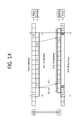
- FIG. 34 shows further yet another example of a timing relationship in a wireless communication system including a BS, an RS, and an Re UE.
- FIG. 35 shows further yet another example of a timing relationship in a wireless communication system including a BS, an RS, and an Re UE.
- FIG. 36 shows further yet another example of a timing relationship in a wireless communication system including a BS, an RS, and an Re UE.
- FIGS. 37 and 38 illustrate the symbol indices of B-UL Tx subframes over which a backhaul SRS is transmitted.
- FIG. 39 is a block diagram showing a source station and a destination station.
- LTE Long Term Evolution
- E-UMTS Evolved-Universal Mobile Telecommunications System
- OFDMA Orthogonal Frequency Division Multiple Access
- SC-FDMA Single Carrier-Frequency Division Multiple Access
- 3GPP LTE/LTE-A is chiefly described below, but the technical feature of the present invention is not limited thereto.
- FIG. 1 shows a wireless communication system including a relay station.
- the wireless communication system 10 including a relay station includes at least one Base Station (BS) 11 .
- the BS 11 provides communication service to a specific geographical area 15 commonly called a cell.
- the cell may be divided into a plurality of areas. Each of the areas is called a sector.
- the one or more cells may exist in one BS.
- the BS refers to a fixed station communicating with a User Equipment (UE) 13 .
- the BS 11 may also be called another terminology, such as an eNB (evolved NodeB), a BTS (Base Transceiver System), an access point, or an AN (Access Network).
- the BS 11 may perform functions, such as connectivity between UEs 14 , management, control, and resource allocation.
- a Relay Station (RS) 12 refers to equipment for relaying a signal between the BS 11 and the UE 14 , and it may also be called another terminology, such as a Relay Node (RN), a repeater, or a relay. Any method, such as AF (amplify and forward) and DF (decode and forward), may be used as a relay method used in the RS, and the technical feature of the present invention is not limited thereto.
- the UE 13 or 14 may be fixed or mobile and may also be called another terminology, such as an MS (Mobile Station), an UT (User Terminal), an SS (Subscriber Station), a wireless device, a PDA (Personal Digital Assistant), a wireless modem, a handheld device, or an AT (Access Terminal.
- a Macro UE (Ma UE) 13 refers to a UE directly communicating with the BS 11
- a relay UE (Re UE) 14 refers to a UE communicating with an RS.
- the Ma UE 13 placed within the cell of the BS 11 may also communicate with the BS 11 via the RS 12 in order to improve the transfer rate according to a diversity effect.
- a link between the BS 11 and the Ma UE 13 is said to be a macro link.
- the macro link may be divided into a macro downlink (M-DL) and a macro uplink (M-UL).
- M-DL means communication from the BS 11 to the Ma UE 13
- M-UL means communication from the Ma UE 13 to the BS 11 .
- a link between the BS 11 and the RS 12 is said to be a backhaul link.
- the backhaul link may be divided into a backhaul downlink (B-DL) and a backhaul uplink (B-UL).
- B-DL means communication from the BS 11 to the RS 12
- B-UL means communication from the RS 12 to the BS 11 .
- a link between the RS 12 and the Re UE 14 is said to be an access link.
- the access link may be divided into an access downlink (A-DL) and an access uplink (A-UL).
- A-DL means communication from the RS 12 to the Re UE 14
- A-UL means communication from the Re UE 14 to the RS 12 .
- the wireless communication system 10 including an RS is a system supporting bi-directional communication.
- the bi-directional communication may be performed using a TDD (Time Division Duplex) mode, an FDD (Frequency Division Duplex) mode and the like.
- the TDD mode use different time resources in UL transmission and DL transmission.
- the FDD mode uses different frequency resources in UL transmission and DL transmission.
- FIG. 2 shows the structure of a radio frame in 3GPP LTE.
- the radio frame includes 10 subframes.
- One subframe consists of two slots.
- the time taken to transmit one subframe is called a TTI (Transmission Time Interval).
- TTI Transmission Time Interval
- the length of one subframe may be 1 millisecond (ms) and the length of one slot may be 0.5 ms.
- FIG. 3 is an exemplary diagram showing a resource grid for one downlink slot.
- one slot includes a plurality of OFDM (orthogonal frequency division multiplexing) symbols in the time domain and includes a plurality of resource blocks (RB) in the frequency domain.
- the OFDM symbol is for representing one symbol period (or symbol time) because 3GPP LTE uses OFDMA in downlink.
- the OFDM symbol may also be called an SC-FDMA symbol according to multiple access scheme.
- the symbol period may hereinafter refer to one OFDM symbol or one SC-FDMA symbol.
- the resource block is a resource allocation unit, and it includes plurality of consecutive subcarriers in one slot.
- a slot (e.g., a downlink slot included in a downlink subframe) includes a plurality of OFDM symbols in the time domain.
- the one downlink slot is illustrated to include 7 OFDM symbols and one resource block is illustrated include 12 subcarriers in the frequency domain, but not limited thereto.
- Each element on the resource grid is called a resource element.
- One resource block includes 12 ⁇ 7 resource elements.
- the number of resource blocks N DL included in the downlink slot is dependent on a DL transmission bandwidth configuration in a cell.
- FIG. 4 shows the structure of a downlink subframe.
- the subframe includes 2 consecutive slots.
- the first 3 OFDM symbols in the first slot of the subframe correspond to a control region to which PDCCH (physical downlink control channel)s are allocated, and the remaining OFDM symbols correspond to a data region to which PDSCH (physical downlink shared channel)s are allocated.
- Control channels such as PCFICH (physical control format indicator channel) and PHICH (physical hybrid automatic repeat request indicator channel), may be allocated to the control region in addition to the PDCCHs.
- a UE can read data information transmitted through the PDSCH by decoding control information transmitted through the PDCCH.
- the control region is illustrated to include the 3 OFDM symbols, but is only exemplary. 2 OFDM symbol or 1 OFDM symbol may be included in the control region. The number of OFDM symbols included in the control region within the subframe can be known through the PCFICH.
- the control region is formed of a logical CCE column including a plurality of CCEs (control channel elements).
- the CCE column is a set of all CCEs which form the control region within one subframe.
- the CCE corresponds to a plurality of resource element groups.
- the CCE may correspond to 9 resource element groups.
- the resource element group is used to define that the control channel is mapped to the resource element.
- One resource element group may consist of 4 resource elements.
- a plurality of PDCCHs may be transmitted within the control region.
- the PDCCH carries control information, such as scheduling allocation.
- the PDCCH is transmitted over one CCE or an aggregation of several consecutive CCEs.
- the format of the PDCCH and the number of possible bits of the PDCCH are determined according to the number of CCEs forming the CCE aggregation.
- the number of CCEs used for PDCCH transmission is called a CCE aggregation level.
- the CCE aggregation level is a CCE unit for searching for a PDCCH.
- the size of the CCE aggregation level is defined by the number of contiguous CCEs.
- the CCE aggregation level may be an element of ⁇ 1, 2, 4, 8 ⁇ .
- the control information transmitting through the PDCCH is called Downlink Control Information (hereinafter DCI).
- DCI includes UL scheduling information, DL scheduling information, system information, UL power control command, control information for paging, control information for a random access response (RACH response) and the like.
- the DCI format includes a format 0 for PUSCH (Physical Uplink Shared Channel) scheduling, a format 1 for the scheduling of one PDSCH codeword, a format 1A for the compact scheduling of one PDSCH codeword, a format 1B for compact scheduling for the rank-1 transmission of a single codeword in a spatial multiplexing mode, a format 1C for the very compact scheduling of a DL-SCH (Downlink Shared Channel), a format 1D for PDSCH scheduling in a multiple user spatial multiplexing mode, a format 2 for PDSCH scheduling in a closed-loop spatial multiplexing mode, a format 2A for PDSCH scheduling in an open-loop spatial multiplexing mode, a format 3 for the transmission of the TPC (Transmission Power Control) command of 2-bit power control for a PUCCH (physical uplink control channel) and a PUSCH, a format 3A for the transmission of the TPC command of 1-bit power control for a PUCCH and a PUSCH and the like.
- FIG. 5 shows the structure of an uplink subframe.
- the uplink subframe may be divided into a control region to which a PUCCH for carrying UL control information is allocated and a data region to which a PUSCH for carrying user data is allocated in the frequency domain.
- a pair of resource blocks (RB) 51 and 52 is allocated to the PUCCH for one UE in the subframe.
- the pair of RBs 51 and 52 occupy different subcarriers in two slots, respectively. This is said that the RB pair allocated to the PUCCH is subjected to frequency hopping at a slot boundary.
- the PUCCH can support multiple formats. That is, the PUCCH can transmit UL control information having a different number of bits per subframe according to a modulation scheme. For example, when BPSK (Binary Phase Shift Keying) is used (PUCCH format 1a), the UL control information of 1 bit can be transmitted through the PUCCH. When QPSK (Quadrature Phase Shift Keying) is used (PUCCH format 1b), the UL control information of 2 bits can be transmitted through the PUCCH.
- BPSK Binary Phase Shift Keying
- QPSK Quadrature Phase Shift Keying
- the PUCCH format may include a format 1, a format 2, a format 2a, a format 2b and the like (For this, reference can be made to Section 5.4 of 3GPP TS 36.211 V8.2.0 (2008 March) “Technical Specification Group Radio Access Network; Evolved Universal Terrestrial Radio Access (E-UTRA); Physical Channels and Modulation (Release 8)”).
- FIG. 6 shows an operation which may be performed by an RS and restriction conditions therefor.
- the RS can perform backhaul uplink transmission (B-UL Tx) and backhaul downlink reception (B-DL Rx) in a relationship with a BS.
- the BS can perform backhaul downlink transmission (B-DL Tx) and backhaul uplink reception (B-UL Rx) in a relationship with the RS.
- the RS can perform access downlink transmission (A-DL Tx) and access uplink reception (A-UL Rx) in a relationship with an Re UE.
- the Re UE can perform access uplink transmission (A-UL Tx) and access downlink reception (A-DL Rx) in a relationship with the RS.
- the BS can perform macro downlink transmission (M-DL Tx) and macro uplink reception (M-UL Rx) in a relationship with an Ma UE.
- M-DL Tx macro downlink transmission
- M-UL Rx macro uplink reception
- an RS cannot transmit and receive signals at the same time in the same frequency band owing to self-interference. That is, the RS cannot perform B-DL Rx and A-DL Tx at the same time. Furthermore, the RS cannot perform B-UL Tx and A-UL Rx at the same time. Accordingly, the transmission and reception of signals in the same frequency band are performed over different subframes.
- the RS when B-DL Rx and A-DL Tx are switched, the RS requires a guard time (or guard period). Likewise, when B-UL Tx and A-UL Rx are switched, the RS requires a guard time.
- the guard time may be about 20 microsecond ( ⁇ s) by taking the transient time characteristic of an analog amplifier, used in the RS, into consideration.
- FIGS. 7 and 8 show examples in which a guard time is disposed within a subframe.
- the guard time may be time duration smaller than one symbol (e.g., one OFDM symbol or one SC-FDMA symbol). That is, in the temporal aspect, the guard time may be part of one symbol.
- the position of the guard time and the size of the guard time may be changed in various ways according to the structure of a backhaul subframe and a timing relationship between access subframes. For example, one of the guard times may be placed at the central symbol of a subframe as shown in FIG. 7 , or the guard times may be placed at the first and the last symbols of a subframe as shown in FIG. 8 .
- a minimum scheduling unit is a subframe.
- an RS performs the switching by the unit of subframe.
- the guard times are placed at the first symbol and the last symbol of a subframe as shown in FIG. 8 . If the guard time is placed within one symbol, although the guard time occupies a time period smaller than one symbol, the related symbol may not be used (parts of symbols that cannot be used in FIGS. 7 and 8 are indicated by ‘N’). That is, the symbol including the guard time is wasted.
- an SRS sounding reference signal
- 3GPP LTE 3GPP LTE
- an SRS sounding reference signal
- One of methods for solving the problem is a method of defining a new symbol.
- a symbol having a time period smaller than that of a conventional symbol (e.g., an OFDM symbol or an SC-FDMA symbol) is defined.
- the waste of radio resources can be prevented by applying the new symbol to the time duration which is wasted owing to a guard time.
- Another method for solving the above problem is to shift a signal transmission/reception subframe between a BS, an RS, and a UE based on offset time information or additional alignment information or both.
- FIG. 9 shows a propagation delay time and an offset time.
- a BS performs B-DL Tx.
- an RS performs B-DL Rx after a propagation delay time Tp. That is, the propagation delay time is the delay time occurring owing to the transmission of a physical signal, in the time taken for a source station to transmit a signal and the time taken for a destination station to receive the signal.
- An offset time To means an intentional offset between the backhaul link subframe and the access link subframe of the RS.
- the RS may perform B-DL Rx and A-DL Tx with the offset time To.
- the information for propagation delay time or the offset time or both can be transmitted from a BS to an RS and a UE.
- the BS may transmit information for the offset time through the synchronization signal of a P-BCH or a physical channel (e.g., a PDCCH).
- a P-BCH synchronization signal of a P-BCH or a physical channel (e.g., a PDCCH).
- the RS or the UE transmits or receive a signal in response to relevant timing.
- FIG. 9( b ) is a diagram except the propagation delay time of FIG. 9( a ). If the propagation delay time is excluded, FIG. 9( a ) can be simply shown as in FIG. 9( b ). In the following description and figures, the propagation delay time is excluded, if necessary, and a timing relationship for signal transmission/reception between a BS, an RS, and a UE is shown.
- FIGS. 10 to 14 are diagrams showing timing relationships between a subframe over which an RN receives a backhaul DL signal from an eNB and a subframe over which the RN transmits an access DL signal to an Re UE on the basis of a macro subframe.
- the propagation delay time is taken into account.
- FIG. 10 shows an example of a timing relationship between the macro subframe of an eNB and the B-DL Rx subframe and the A-DL Tx subframe of an RN.
- the macro subframe and the B-DL Tx subframe are aligned.
- the B-DL Rx subframe is temporally placed behind the B-DL Tx subframe by a propagation delay time Tp by taking the propagation delay time Tp into account.
- the A-DL Tx subframe is shifted by a fixed offset time To and placed in the B-DL Rx subframe. It corresponds to a case where a switching time in the RN is longer than a cyclic prefix.
- the RN transmits a control signal to the Re UE using K symbols.
- the number of symbols used in an R-PDCCH through which the RN transmits the control signal to the Re UE is K (the same hereinafter).
- the RN can receive the backhaul DL signal using symbols from a symbol index 3 to a symbol index 13 (i.e., the last symbol of the subframe).
- FIG. 11 shows another example of a timing relationship between the macro subframe and the B-DL Tx subframe of an eNB and the B-DL Rx subframe and the A-DL Tx subframe of an RN.
- This timing relationship corresponds to a case where the switching time of the RN is very short (e.g., shorter than a cyclic prefix) and a case where the B-DL Rx subframe and the A-DL Tx subframe are aligned.
- the switching time may be very short according to the performance of an analog amplifier used in the RN.
- the guard time is placed ahead of a symbol having a symbol index 2 in the B-DL Rx subframe and placed behind a symbol having a symbol index 13. Since the time period of the guard time is shorter than the cyclic prefix, it may be said that synchronization between symbols is not influenced.
- FIGS. 12 to 14 show yet another example of a timing relationship between the macro subframe and the B-DL Tx subframe of an eNB and the B-DL Rx subframe and the A-DL Tx subframe of an RN.
- the B-DL Tx subframe of the eNB and the A-DL Tx subframe of the RN are started on the same time (i.e., synchronized).
- the B-DL Rx subframe may be shifted from the B-DL Tx subframe by a propagation delay time Tp.
- This timing relationship corresponds to a case where the propagation delay time Tp is shorter than one symbol period L, the propagation delay time Tp is shorter than a guard time G1, and a (Tp+guard time G2) is shorter than a symbol period L.
- the RN can receive a backhaul DL signal from a symbol having a symbol index M (K or higher than K) to a symbol having a symbol index of n.
- FIGS. 15 to 21 show examples of a timing relationship between a B-UL Tx subframe over which an RN transmits a backhaul UL signal to an eNB and an A-UL Rx subframe over which an RN receives an access UL signal from an Re UE, on the basis of the macro subframe of the eNB.
- the propagation delay time is taken into account.
- the B-UL Tx subframe and the A-UL Rx subframe have a time difference of a fixed offset value.
- FIG. 15 shows the example in which the offset time To has a negative value.
- the RN can puncture a symbol having an SC-FDMA symbol index of 0 and transmit the backhaul UL signal using 13 symbols having an SC-FDMA symbol index 1 to an SC-FDMA symbol index 13 (in case of a normal CP). That is, the offset time is placed between the B-UL Tx subframe over which the RN transmits the backhaul UL signal and the A-UL Rx subframe over which the RN receives the access UL signal from the Re UE, so that the RN can use the 13 symbols to transmit the backhaul UL signal.
- FIG. 16 there is no time difference between the B-UL Tx subframe and the A-UL Rx subframe of an RN. That is, an offset value does not exist.
- This timing relationship corresponds to a case where the B-UL Tx subframe and the A-UL Rx subframe of the RN are aligned and the switching time of the RN is very short (e.g., a case where the switching time is shorter than a cyclic prefix).
- the switching time of the RN is very short, there is no problem although the guard time is very short. Accordingly, the guard time necessary to switch the backhaul UL Tx and the access UL Rx of the RN rarely has an influence on the subframe structure.
- the RN can transmit the backhaul UL signal using 14 symbols having SC-FDMA symbol indices 0 to 13.
- FIG. 17 a time difference having a fixed offset value is placed between the B-UL Tx subframe and the A-UL Rx subframe of an RN.
- FIG. 17 shows an example in which the offset time has a negative value.
- FIG. 17 differs from FIG. 16 in that a guard time necessary between the A-UL Rx subframe and the B-UL Tx subframe of the RN is placed in the A-UL Rx subframe. Accordingly, the RN can transmit a backhaul UL signal using all 14 symbols having SC-FDMA symbol indices 0 to 13 (in case of a normal CP). Meanwhile, since the guard time is placed at the last symbol of the A-UL Rx subframe, the Re UE may be difficult to transmit an SRS over the last symbol. This is because the RN is difficult to receive the SRS.
- FIG. 18 a time difference of a fixed offset value is placed between the B-UL Tx subframe and the A-UL Rx subframe of an RN.
- FIG. 18 is different from FIG. 17 in that the offset time has a positive value. That is, the A-UL Rx subframe is temporally ahead of the B-UL Tx subframe by the offset time.
- the RN can transmit a backhaul UL signal using 13 symbols having SC-FDMA symbol indices 0 to 12 (in case of a normal CP).
- the last symbol (i.e., a symbol having a symbol index 13) of the B-UL Tx subframe cannot be used owing to a guard time.
- the A-UL Rx subframe of an RN and the B-UL Rx subframe of an eNB are aligned, and a B-UL Tx subframe is placed by taking a propagation delay time into account.
- the RN can transmit a backhaul UL signal during a period from a symbol having a symbol index N of 1 or higher to a symbol having a symbol index N of 12 over the B-UL Tx subframe (in case of a normal CP). That is, the RN can transmit the backhaul UL signal over the 12 symbols.
- FIG. 20 differs from FIG. 19 in an application condition.
- the timing relationship such as that shown in FIG. 20 , may be applied to a case where the sum of a propagation delay time Tp and a guard time G1 is smaller than one symbol period L, a guard time G2 is smaller than the propagation delay time Tp, and the propagation delay time Tp is smaller than the symbol period L.
- the RN can transmit a backhaul UL signal using a period from a symbol having a symbol index N of 1 to a symbol having a symbol index N of 13 (in case of a normal CP). That is, the RN can transmit the backhaul UL signal using the 13 symbols.
- the A-UL Rx subframe of an RN and the B-UL Rx subframe of an eNB are aligned, and a B-UL Tx subframe is placed by taking a propagation delay time into account.
- the RN can transmit a backhaul UL signal using 12 symbols having symbol indices N of 2 to 13 (in case of a normal CP).
- FIG. 22 shows an example of a timing relationship in a wireless communication system including an eNB, an RN, and an Re UE. A propagation delay time is not shown in FIG. 22 .
- the starting positions of subframe are synchronized between the eNB and the RN or between the eNB and the UE.
- the RN receives (A-UL Rx) an access UL signal transmitted by the UE and transmits (B-UL Tx) a backhaul UL signal over a subframe #(n+2).
- the RN cannot transmit the backhaul UL signal because a guard time is placed within the subframe, as shown in FIG. 22 , when the RN transmits (B-UL Tx) the backhaul UL signal over the subframe #(n+2) or a subframe #n.
- the RN transmits the backhaul UL signal using a shortened format (i.e., the first symbol and the last symbol from among 14 symbols included in the subframe are punctured and only 12 symbols are used). If the backhaul UL signal is transmitted using the shortened format, in order to transmit a backhaul SRS (indicated by S′), the RN has to transmit the SRS of a special form. That is, the RN generates the SRS of a special form, defined for a period smaller than one symbol, and transmits the backhaul SRS over the last symbol of the subframe.
- a shortened format i.e., the first symbol and the last symbol from among 14 symbols included in the subframe are punctured and only 12 symbols are used.
- FIG. 23 shows another example of a timing relationship in a wireless communication system including an eNB, an RN, and an Re UE. A propagation delay time is not shown in FIG. 23 .
- an offset having a fixed time exists in the timing relationship between the subframes of the eNB and the RN and in the timing relationship between the subframes of the RN and the UE.
- a subframe #(n+1) the A-DL Tx subframe and the A-UL Rx subframe of the RN, and the A-DL Rx subframe and the A-UL Tx subframe of the UE are forwardly shifted by an offset time To on the basis of an M-DL Tx subframe and an M-UL Rx subframe which are macro subframes.
- the offset time To is a value given by the eNB and may be determined according to the structure of a subframe used in the backhaul link.
- the RN can transmit a backhaul UL signal using 13 symbols (in case of a normal CP). That is, the method described above with reference to FIG. 18 may be applied to the timing relationship.
- the RN can receive a backhaul DL signal using 10 or 11 symbols (in case of a normal CP). That is, any one of the methods described above with reference to FIGS. 12 to 14 may be applied to the timing relationship.
- FIG. 24 shows yet another example of a timing relationship in a wireless communication system including an eNB, an RN, and an UE. A propagation delay time is not shown in FIG. 24 .
- an offset having a fixed time exists in the timing relationship between the subframes of the eNB and the RN and the timing relationship between the subframes of the RN and the UE.
- a subframe #(n+1) the A-DL Tx subframe and the A-UL Rx subframe of the RN and the A-DL Rx subframe and the A-UL Tx subframe of the UE are backwardly shifted by an offset time To on the basis of an M-DL Tx subframe and an M-UL Rx subframe which are macro subframes.
- the offset time To is a value given by the eNB and may be determined according to the structure of a subframe used in the backhaul link.
- the RN can transmit a backhaul UL signal using 13 symbols (in case of a normal CP).
- the method described above with reference to FIG. 15 may be applied to the timing relationship.
- FIG. 24 is different from FIG. 23 in that the RN can use the last symbol of the B-UL Tx subframe over which the backhaul UL signal is transmitted and the B-UL Tx subframe is synchronized with a macro subframe for each symbol. Accordingly, there is an advantage in that a backhaul SRS (indicated by S′) can be multiplexed with an SRS transmitted by an Ma UE and then transmitted. Alternatively, the RN may transmit the backhaul UL signal using all 14 symbols (in case of a normal CP).
- the method described with reference to FIG. 17 may be applied to the timing relationship. If the method described with reference to FIG. 17 is applied, the RN does not receive an access UL signal over the last symbol of the A-UL Rx subframe, but places a guard time G1 in the last symbol of the A-UL Rx.
- the RN can receive a backhaul DL signal using symbols having a symbol index K+1 to the last index. That is, the method described above with reference to FIG. 10 may be applied to this timing relationship.
- FIG. 25 shows further yet another example of a timing relationship in a wireless communication system including an eNB, an RN, and an UE.
- a propagation delay time is not shown in FIG. 25 .
- the macro subframes (i.e., an M-DL Tx subframe and an M-UL Rx subframe) of the eNB are misaligned.
- the access subframes (i.e., an A-DL Tx subframe and an A-UL Rx subframe) of the RN are aligned.
- the access subframe of the RN is shifted from the backhaul subframe of the RN by an offset time To. That is, the access subframe of the RN is temporally ahead of the backhaul subframe of the RN by the offset time To. Because of the offset time, the RN can transmit a backhaul UL signal using the 13 symbols of the B-UL Tx subframe (in case of a normal CP).
- the RN transmits a backhaul SRS (indicated by S′) over the B-UL Tx subframe, there is an advantage in that the symbol is synchronized with a symbol through which an Ma UE transmits an SRS by symbol unit.
- FIG. 26 and FIG. 27 show further yet another example of a timing relationship in a wireless communication system including an eNB, an RN, and an UE.
- a propagation delay time is not shown in FIGS. 26 and 27 .
- the eNB may forwardly shift an M-UL Rx subframe so that it is synchronized with a B-UL Rx subframe for each symbol unit.
- the B-DL Tx subframe of the eNB and the B-DL Rx subframe of the RN are synchronized with each other.
- the B-UL Rx subframe of the eNB and the B-UL Tx subframe of the RN are synchronized with each other.
- access subframes i.e., an A-DL Tx subframe and an A-UL Rx subframe
- An M-UL Rx subframe and the B-UL Rx subframe can be synchronized with each other for each symbol according to this timing relationship. Accordingly, there is an advantage in that the RN does not need to transmit a special SRS in which a backhaul SRS is placed in the time domain smaller than one symbol. If the synchronization is performed for each symbol, interference between an SRS transmitted by an Ma UE and the backhaul SRS transmitted by the RN is reduced.
- FIG. 27 is different from FIG. 26 in that a guard time is indicated in another period.
- FIG. 28 shows further yet another example of a timing relationship in a wireless communication system including an eNB, an RN, and an UE.
- a propagation delay time is not shown in FIG. 28 .
- all the macro subframe and the backhaul subframe of the eNB, the backhaul subframe and the access subframe of the RN, and the access subframes of the UE are aligned and synchronized with each other.
- the eNB wastes 2 symbols owing to a guard time in a B-DL Tx subframe, and the RN also wastes 2 symbols owing to a guard time in a B-DL Rx subframe.
- the B-UL Rx subframe of the eNB and the B-UL Tx subframe of the RN.
- a part indicated by ‘U’ is the wasted region. If some of the symbols are referred to as partial symbols, the waste problem of the partial symbols can be solved by defining and using a new symbol as described above.
- FIG. 29 shows further yet another example of a timing relationship in a wireless communication system including an eNB, an RN, and an UE.
- a propagation delay time is taken into account and shown in FIG. 29 .
- a round trip delay time between the eNB and the RN is indicated by RTD eNB-RS
- a round trip delay time between the RN and the UE is indicated by RTD RS-UE .
- the propagation delay time may be (RTD eNB-RS /2) between the eNB and the RN and may be (RTD RS-UE /2) between the RN and the UE.
- the B-UL Rx subframe of the eNB is aligned with an M-UL Rx subframe.
- the B-UL Tx subframe of the RN may be placed ahead of the B-UL Rx subframe of the eNB by (RTD eNB-RS /2) by taking the propagation delay time into account.
- the B-DL Rx subframe of the RN may be placed behind the B-DL Tx subframe of the eNB by (RTD eNB-RS /2).
- the B-UL Tx subframe and the B-DL Rx subframe of the RN may be placed with a difference by RTD eNB-RS .
- the backhaul link subframes i.e., the B-UL Tx subframe and the B-DL Rx subframe
- the backhaul link subframes i.e., the B-UL Tx subframe and the B-DL Rx subframe
- the B-DL Rx subframe and the A-DL Tx subframe are switched and used
- the B-UL Tx subframe and the A-UL Rx subframe are switched and used.
- the A-DL Tx subframe and the A-UL Rx subframe of the RN have also to be placed with a difference by RTD eNB-RS by taking the above into account.
- the UE has only to transmit an access UL signal ahead of (RTD RS-UE /2) by taking the propagation delay time into consideration. That is, the A-UL Tx subframe of the UE has only to be placed ahead of the A-UL Rx subframe of the RN by (RTD RS-UE /2).
- RTD RS-UE /2 access downlink
- the A-DL Tx subframe of the RN has only to be placed ahead of the A-DL Rx subframe of the UE by (RTD RS-UE /2).
- the A-UL Tx subframe and the A-DL Rx subframe of the UE should not be placed with the difference of RTD RS-UE , but have to be placed with a difference of (RTD eNB-RS +RTD RS-UE ).
- a legacy UE e.g., a UE operated according to 3GPP LTE release 8
- the legacy UE transmits a PRACH (physical random access channel) preamble like in a conventional method used in a relationship with an eNB because it does not know whether a destination station is the eNB or an RN.
- PRACH physical random access channel
- the legacy UE has to transmit a preamble having a large coverage when the RN has a small cell size.
- radio resources useful for the RN to transmit a backhaul UL signal can be maximized.
- FIG. 30 shows further yet another example of a timing relationship in a wireless communication system including an eNB, an RN, and an UE.
- a propagation delay time is taken into account and shown in FIG. 30 .
- downlink subframes i.e., a B-DL Rx subframe and an A-DL Tx subframe
- uplink subframes i.e., a B-UL Tx subframe and an A-UL Rx subframe
- the B-UL Tx subframe and the B-DL Rx subframe of the RN may be placed behind the B-UL Rx subframe and the B-DL Tx subframe of the eNB by (RTD eNB-RS /2).
- This timing relationship does not have an influence on a legacy UE (e.g., a UE operated according to 3GPP LTE release 8).
- Resources that may be used by the RN in backhaul UL transmission are reduced by RTD eNB-RS in the time domain, but there is an advantage in that the legacy UE can be operated by applying the same time difference between an A-DL Rx subframe and an A-UL Tx subframe.
- RTD eNB-RS is greater than a guard time, the RN may multiplex a backhaul SRS with an SRS transmitted by an Ma UE and then transmit the multiplexed SRS.
- Timing relationships in which an eNB, an RN, and a UE transmit and receive signals for each symbol of a subframe are described below.
- a part indicated by ‘G’ means a guard time
- ‘S’ means an SRS transmitted from the UE to the eNB
- ‘S′’ means a backhaul SRS transmitted from the RN to the eNB.
- a propagation delay time is not shown.
- FIG. 31 shows further yet another example of a timing relationship in a wireless communication system including an eNB, an RN, and an Re UE.
- an M-UL Rx subframe, an M-DL Tx subframe, a B-DL Rx subframe, a B-UL Tx subframe, an A-DL Rx subframe, and A-UL Tx subframes are aligned on the basis of a subframe boundary.
- the B-DL Rx subframe and the B-UL Tx subframe are aligned on the basis of the subframe boundary, but include guard times. Accordingly, the B-DL Rx subframe and the B-UL Tx subframe are not aligned for each symbol.
- the guard time included in the B-DL Rx subframe may be included in a different symbol from that of FIG. 31 , and the start point of a symbol at which a backhaul DL signal is received from the eNB over the B-UL Tx subframe may be different form that of FIG. 31 .
- FIG. 32 shows further yet another example of a timing relationship in a wireless communication system including an eNB, an RN, and an Re UE.
- a B-DL Rx subframe, a B-UL Tx subframe, an A-DL Rx subframe, and an A-UL Tx subframes have different points of timing based on a subframe boundary in regard to an M-UL Rx subframe and an M-DL Tx subframe. That is, the B-DL Rx subframe and the B-UL Tx subframe of the RN and the A-DL Rx subframe and the A-UL Tx subframe of the Re UE have a negative offset time.
- the eNB can transmit information about the offset time so that the RN and the Re UE have a timing relationship.
- a symbol through which a backhaul SRS is transmitted, in the B-UL Tx subframe, is aligned with a symbol through which a macro SRS is received over the M-UL Rx subframe by symbol unit.
- FIG. 33 shows further yet another example of a timing relationship in a wireless communication system including an eNB, an RN, and an Re UE.
- the B-DL Rx subframe and the B-UL Tx subframe of the RN and the A-DL Rx subframe and the A-UL Tx subframe of the Re UE have a positive timing offset in regard to an M-UL Rx subframe and an M-DL Tx subframe.
- a backhaul SRS transmitted over the B-UL Tx subframe may be transmitted over a different symbol (the thirteenth symbol of the B-UL Tx subframe) from a macro SRS (i.e., a macro SRS received over the M-UL Rx subframe) transmitted by an Ma UE. Accordingly, the macro SRS and the backhaul SRS need not to be multiplexed in the last symbol (a fourteenth symbol) of the subframe.
- FIG. 34 shows further yet another example of a timing relationship in a wireless communication system including an eNB, an RN, and an Re UE.
- an M-DL Tx subframe, a B-DL Rx subframe, and an A-DL Rx subframe are aligned on the basis of a subframe boundary. That is, in a macro subframe, a backhaul subframe, and an access subframe, downlink subframes are aligned on the basis of the subframe boundary.
- a B-UL Tx subframe and an A-UL Tx subframe are misaligned on the basis of the subframe boundary.
- the eNB can apply this timing relationship by transmitting an additional timing adjustment command (indicated by TA′) to the RN or the UE.
- the additional timing adjustment command may be a signal which is additionally transmitted in addition to the existing timing adjustment command in order to compensate for a propagation delay time or a round trip time.
- FIG. 34 shows an example in which the additional timing adjustment command TA′ having a negative value is performed. That is, FIG. 34 shows an example in which the B-UL Tx subframe and the A-UL Tx subframe are temporally shifted backwardly. In this timing relationship, a backhaul SRS and a macro SRS transmitted over the B-UL Tx subframe can be aligned for each symbol.
- FIG. 35 shows further yet another example of a timing relationship in a wireless communication system including an eNB, an RN, and an Re UE.
- FIG. 35 an M-DL Tx subframe, a B-DL Rx subframe, and an A-DL Rx subframe are aligned on the basis of a subframe boundary.
- an M-UL Rx subframe, a B-UL Tx subframe, and an A-UL Tx subframe are misaligned on the basis of the subframe boundary.
- FIG. 35 is different from FIG. 34 in that an additional timing adjustment command is set to a positive value. That is, FIG. 35 shows an example in which the B-UL Tx subframe and the A-UL Tx subframe are temporally shifted forwardly.
- FIG. 36 shows further yet another example of a timing relationship in a wireless communication system including an eNB, an RN, and an Re UE.
- An M-DL Tx subframe, a B-DL Rx subframe, and an A-DL Rx subframe are aligned on the basis of a subframe boundary.
- An additional timing adjustment command having a positive value is applied to an M-UL Rx subframe, a B-UL Tx subframe, and an A-UL Tx subframe.
- FIG. 36 differs from FIG. 35 in that the degree that the B-UL Tx subframe and the A-UL Tx subframe are shifted is one symbol or more.
- the B-UL Tx subframe and the A-UL Tx subframe may be forwardly shifted by (one symbol+a guard time).
- the B-UL Tx subframe and the A-UL Tx subframe do not temporally overlap with each other because they are forwardly shifted.
- a backhaul SRS can be transmitted over the first symbol other than a guard time.
- the backhaul SRS can be aligned with the macro SRS of the M-UL Rx subframe by symbol unit, as shown in FIG. 36 . Since the macro SRS and the backhaul SRS can be multiplexed and transmitted, a collision with a PUSCH and a PUCCH received through the M-UL Rx subframe can be avoided.
- the eNB may allow an Ma UE to always transmit data in a shortened format. For example, irrespective of whether a macro SRS has been transmitted, the Ma UE can always transmit data in the shortened format.
- the eNB may inform the RN of a subframe through which the Ma UE does not transmit the macro SRS and may configure the subframe as a subframe using the shortened format.
- the RN may take the amount of possible backhaul resources into account when determining whether the backhaul SRS is transmitted, the format of an R-PUSCH and the like. The utilization of resources can be increased by sharing information about macro SRS transmission timing and backhaul SRS transmission timing between the eNB and the RN.
- FIGS. 37 and 38 illustrate the symbol indices of B-UL Tx subframes over which a backhaul SRS is transmitted.
- the backhaul SRS can be transmitted over the first symbol of a B-UL Tx subframe other than guard times.
- the symbol indices of the B-UL Tx subframe may be assigned for each symbol (e.g., for an OFDM symbol or SC-FDMA symbol) in time periods other than the guard times.
- the index of the first symbol through which the backhaul SRS is transmitted is assigned 12, and indices from 0 to 11 are sequentially assigned to subsequent symbols. According to the method of assigning symbol indices, it may be said that the backhaul SRS is always transmitted through the symbol 12 despite the position of physical resources.
- the index of a first symbol through which a backhaul SRS is transmitted assigned 0, and indices from 1 to 12 are sequentially assigned to subsequent symbols. If a backhaul SRS is transmitted, 13 symbols may be used in the B-UL Tx subframe. If a backhaul SRS is not transmitted, 12 symbols may be used in the B-UL Tx subframe.
- FIG. 39 is a block diagram showing a source station and a destination station.
- the source station 10 may be an eNB.
- the source station 10 includes a processor 11 , memory 12 , and a Radio Frequency (RF) unit 13 .
- the processor 11 implements the proposed functions, processes, and/or methods. That is, the processor 11 can transmit a synchronization signal to the destination station and can transmit information for an offset time and an additional timing adjustment command TA′.
- the layers of a radio interface protocol may be implemented by the processor 11 .
- the memory 12 is coupled to the processor 11 and configured to store various pieces of information for driving the processor 11 .
- the RF unit 13 is coupled to the processor 11 and configured to transmit and/or receive a radio signal.
- the destination station 20 may be a UE (i.e., an RN, an Ma UE, or an Re UE).
- the destination station 20 includes a processor 21 , memory 22 , and an RF unit 23 .
- the processor 21 receives a synchronization signal, information for an offset time, and an additional timing adjustment command and determines the timing of a subframe over which a signal is transmitted or received.
- the layers of a radio interface protocol may be implemented by the processor 21 .
- the memory 22 is coupled to the processor 21 and configured to store various pieces of information for driving the processor 21 .
- the RF unit 23 is coupled to the processor 21 and configured to transmit and/or receive a radio signal.
- the processor 11 , 21 can include an Application-Specific Integrated Circuit (ASIC), other chipset, a logic circuit, a data processor and/or a converter for converting a baseband signal and a radio signal, and vice versa.
- the memory 12 , 22 may include Read-Only Memory (ROM), Random Access Memory (RAM), flash memory, a memory card, a storage medium and/or other storage devices.
- the RF unit 13 , 23 includes one or more antennas for transmitting and/or receiving a radio signal.
- the above schemes may be implemented using a module (process, function or the like) which performs the above functions.
- the module can be stored in the memory 12 , 22 and executed by the processor 11 , 21 .
- the memory 12 , 22 may be placed inside or outside the processor 11 , 21 and connected to the processor 11 , 21 through a variety of well-known means.
Priority Applications (2)
| Application Number | Priority Date | Filing Date | Title |
|---|---|---|---|
| US14/044,577 US9001876B2 (en) | 2009-02-16 | 2013-10-02 | Method and apparatus for transmitting and receiving signal from relay station in radio communication system |
| US14/657,976 US9698946B2 (en) | 2009-02-16 | 2015-03-13 | Method and apparatus for transmitting and receiving signal from relay station in radio communication system |
Applications Claiming Priority (10)
| Application Number | Priority Date | Filing Date | Title |
|---|---|---|---|
| US15295109P | 2009-02-16 | 2009-02-16 | |
| US18726609P | 2009-06-15 | 2009-06-15 | |
| US21972709P | 2009-06-23 | 2009-06-23 | |
| US23616209P | 2009-08-24 | 2009-08-24 | |
| US29886210P | 2010-01-27 | 2010-01-27 | |
| PCT/KR2010/000950 WO2010093221A2 (ko) | 2009-02-16 | 2010-02-16 | 무선통신 시스템에서 중계국의 신호 송수신 방법 및 장치 |
| KR10-2010-0013907 | 2010-02-16 | ||
| KR1020100013907A KR101595131B1 (ko) | 2009-02-16 | 2010-02-16 | 무선통신 시스템에서 중계국의 신호 송수신 방법 및 장치 |
| US201113201805A | 2011-08-16 | 2011-08-16 | |
| US14/044,577 US9001876B2 (en) | 2009-02-16 | 2013-10-02 | Method and apparatus for transmitting and receiving signal from relay station in radio communication system |
Related Parent Applications (2)
| Application Number | Title | Priority Date | Filing Date |
|---|---|---|---|
| PCT/KR2010/000950 Continuation WO2010093221A2 (ko) | 2008-06-15 | 2010-02-16 | 무선통신 시스템에서 중계국의 신호 송수신 방법 및 장치 |
| US13/201,805 Continuation US8576900B2 (en) | 2008-06-15 | 2010-02-16 | Method and apparatus for transmitting and receiving signal from relay station in radio communication system |
Related Child Applications (1)
| Application Number | Title | Priority Date | Filing Date |
|---|---|---|---|
| US14/657,976 Continuation US9698946B2 (en) | 2009-02-16 | 2015-03-13 | Method and apparatus for transmitting and receiving signal from relay station in radio communication system |
Publications (2)
| Publication Number | Publication Date |
|---|---|
| US20140029508A1 US20140029508A1 (en) | 2014-01-30 |
| US9001876B2 true US9001876B2 (en) | 2015-04-07 |
Family
ID=56291154
Family Applications (2)
| Application Number | Title | Priority Date | Filing Date |
|---|---|---|---|
| US14/044,577 Active US9001876B2 (en) | 2009-02-16 | 2013-10-02 | Method and apparatus for transmitting and receiving signal from relay station in radio communication system |
| US14/657,976 Active 2030-07-07 US9698946B2 (en) | 2009-02-16 | 2015-03-13 | Method and apparatus for transmitting and receiving signal from relay station in radio communication system |
Family Applications After (1)
| Application Number | Title | Priority Date | Filing Date |
|---|---|---|---|
| US14/657,976 Active 2030-07-07 US9698946B2 (en) | 2009-02-16 | 2015-03-13 | Method and apparatus for transmitting and receiving signal from relay station in radio communication system |
Country Status (2)
| Country | Link |
|---|---|
| US (2) | US9001876B2 (ko) |
| KR (1) | KR101595131B1 (ko) |
Cited By (2)
| Publication number | Priority date | Publication date | Assignee | Title |
|---|---|---|---|---|
| US20150188676A1 (en) * | 2009-02-16 | 2015-07-02 | Lg Electronics Inc. | Method and apparatus for transmitting and receiving signal from relay station in radio communication system |
| US10652059B2 (en) * | 2018-06-19 | 2020-05-12 | CoreTigo, Ltd. | Mission critical wireless communication link master gateway |
Families Citing this family (11)
| Publication number | Priority date | Publication date | Assignee | Title |
|---|---|---|---|---|
| EP2690799A4 (en) * | 2011-03-25 | 2014-10-08 | Lg Electronics Inc | TERRESTRIAL LINK SUB-FRAME STRUCTURE IN A MOBILE COMMUNICATION SYSTEM AND ITS INFORMATION TRANSMISSION METHOD |
| IN2014CN03338A (ko) | 2011-11-04 | 2015-07-03 | Mitsubishi Electric Corp | |
| US10344597B2 (en) * | 2015-08-17 | 2019-07-09 | United Technologies Corporation | Cupped contour for gas turbine engine blade assembly |
| CN108029098B (zh) | 2015-09-25 | 2022-07-22 | 瑞典爱立信有限公司 | 用于在无线网络中降低干扰的方法和网络节点 |
| WO2017195653A1 (ja) * | 2016-05-10 | 2017-11-16 | 株式会社Nttドコモ | 無線通信装置及び無線通信方法 |
| US10375707B2 (en) * | 2016-08-04 | 2019-08-06 | Qualcomm Incorporated | Dynamic resource allocation in wireless network |
| CN108282303B (zh) | 2017-01-06 | 2023-03-10 | 北京三星通信技术研究有限公司 | 信号传输的方法及设备 |
| EP4120655A1 (en) * | 2017-12-21 | 2023-01-18 | ASUSTek Computer Inc. | Method and apparatus for transmission and reception in backhaul link in a wireless communication system |
| US11503555B2 (en) * | 2018-08-17 | 2022-11-15 | Qualcomm Incorporated | Dynamic timing adjustment for new radio integrated access and backhaul node |
| EP3692752B1 (en) * | 2018-09-27 | 2022-11-02 | Samsung Electronics Co., Ltd. | Improvements in and relating to power control in integrated access and backhaul |
| US20220182977A1 (en) * | 2019-05-28 | 2022-06-09 | Apple Inc. | Soft resource signaling in relay networks |
Citations (11)
| Publication number | Priority date | Publication date | Assignee | Title |
|---|---|---|---|---|
| US6108364A (en) | 1995-08-31 | 2000-08-22 | Qualcomm Incorporated | Time division duplex repeater for use in a CDMA system |
| JP2007166620A (ja) | 2005-12-10 | 2007-06-28 | Samsung Electronics Co Ltd | マルチホップ中継方式のセルラネットワークにおける動作転換ギャップを調整するための装置及び方法 |
| WO2007100232A1 (en) | 2006-03-03 | 2007-09-07 | Samsung Electronics Co., Ltd. | Apparatus and method for supporting relay service in a multi-hop relay broadband wireless access communication system |
| US20080043647A1 (en) | 2006-08-18 | 2008-02-21 | Fujitsu Limited | Radio relay system and radio relay station |
| JP2008048218A (ja) | 2006-08-17 | 2008-02-28 | Fujitsu Ltd | 無線通信システムにおける無線中継通信方法並びに無線基地局及び無線中継局 |
| US20080212516A1 (en) | 2007-03-02 | 2008-09-04 | Samsung Electronics Co., Ltd. | Appartus and method for negotiating frame offset between base station and relay station in broadband wireless communication system using multi-hop relay scheme |
| KR20080093257A (ko) | 2007-04-16 | 2008-10-21 | 삼성전자주식회사 | Tdd 방식을 사용하는 중계기에서 전송 신호를 분리하는스위치 제어 방법 및 장치 |
| US20090122731A1 (en) * | 2007-10-01 | 2009-05-14 | Qualcomm Incorporated | Partial discarding of cyclic prefix for efficient tdd or half-duplex fdd operation |
| US20090279458A1 (en) * | 2008-03-24 | 2009-11-12 | Texas Instruments Incorporated | Uplink and Downlink Hybrid Automatic Repeat Request In Time Division Multiplex Communications |
| US8032183B2 (en) * | 2007-07-16 | 2011-10-04 | Alcatel Lucent | Architecture to support network-wide multiple-in-multiple-out wireless communication |
| US8576900B2 (en) * | 2008-06-15 | 2013-11-05 | Lg Electronics Inc. | Method and apparatus for transmitting and receiving signal from relay station in radio communication system |
Family Cites Families (3)
| Publication number | Priority date | Publication date | Assignee | Title |
|---|---|---|---|---|
| US8462676B2 (en) * | 2006-10-17 | 2013-06-11 | Intel Corporation | Frame structure for support of large delay spread deployment scenarios |
| KR101595131B1 (ko) * | 2009-02-16 | 2016-02-18 | 엘지전자 주식회사 | 무선통신 시스템에서 중계국의 신호 송수신 방법 및 장치 |
| JP5373924B2 (ja) | 2009-02-16 | 2013-12-18 | エルジー エレクトロニクス インコーポレイティド | 無線通信システムにおける中継局の信号送受信方法及び装置 |
-
2010
- 2010-02-16 KR KR1020100013907A patent/KR101595131B1/ko active IP Right Grant
-
2013
- 2013-10-02 US US14/044,577 patent/US9001876B2/en active Active
-
2015
- 2015-03-13 US US14/657,976 patent/US9698946B2/en active Active
Patent Citations (15)
| Publication number | Priority date | Publication date | Assignee | Title |
|---|---|---|---|---|
| US6108364A (en) | 1995-08-31 | 2000-08-22 | Qualcomm Incorporated | Time division duplex repeater for use in a CDMA system |
| JP2007110754A (ja) | 1995-08-31 | 2007-04-26 | Qualcomm Inc | Cdmaシステムで使用するための時分割デュプレックス中継器 |
| JP2007166620A (ja) | 2005-12-10 | 2007-06-28 | Samsung Electronics Co Ltd | マルチホップ中継方式のセルラネットワークにおける動作転換ギャップを調整するための装置及び方法 |
| US7952988B2 (en) | 2005-12-10 | 2011-05-31 | Samsung Electronics Co., Ltd | Apparatus and method of controlling action change gap in multi-hop relay cellular network |
| WO2007100232A1 (en) | 2006-03-03 | 2007-09-07 | Samsung Electronics Co., Ltd. | Apparatus and method for supporting relay service in a multi-hop relay broadband wireless access communication system |
| JP2008048218A (ja) | 2006-08-17 | 2008-02-28 | Fujitsu Ltd | 無線通信システムにおける無線中継通信方法並びに無線基地局及び無線中継局 |
| KR20080016496A (ko) | 2006-08-18 | 2008-02-21 | 후지쯔 가부시끼가이샤 | 무선 중계 시스템 및 무선 중계국 장치 |
| US20080043647A1 (en) | 2006-08-18 | 2008-02-21 | Fujitsu Limited | Radio relay system and radio relay station |
| US20080212516A1 (en) | 2007-03-02 | 2008-09-04 | Samsung Electronics Co., Ltd. | Appartus and method for negotiating frame offset between base station and relay station in broadband wireless communication system using multi-hop relay scheme |
| KR20080080724A (ko) | 2007-03-02 | 2008-09-05 | 삼성전자주식회사 | 다중홉 릴레이 방식을 사용하는 광대역 무선통신시스템에서기지국과 중계국간 프레임 오프셋 교섭 장치 및 방법 |
| KR20080093257A (ko) | 2007-04-16 | 2008-10-21 | 삼성전자주식회사 | Tdd 방식을 사용하는 중계기에서 전송 신호를 분리하는스위치 제어 방법 및 장치 |
| US8032183B2 (en) * | 2007-07-16 | 2011-10-04 | Alcatel Lucent | Architecture to support network-wide multiple-in-multiple-out wireless communication |
| US20090122731A1 (en) * | 2007-10-01 | 2009-05-14 | Qualcomm Incorporated | Partial discarding of cyclic prefix for efficient tdd or half-duplex fdd operation |
| US20090279458A1 (en) * | 2008-03-24 | 2009-11-12 | Texas Instruments Incorporated | Uplink and Downlink Hybrid Automatic Repeat Request In Time Division Multiplex Communications |
| US8576900B2 (en) * | 2008-06-15 | 2013-11-05 | Lg Electronics Inc. | Method and apparatus for transmitting and receiving signal from relay station in radio communication system |
Cited By (4)
| Publication number | Priority date | Publication date | Assignee | Title |
|---|---|---|---|---|
| US20150188676A1 (en) * | 2009-02-16 | 2015-07-02 | Lg Electronics Inc. | Method and apparatus for transmitting and receiving signal from relay station in radio communication system |
| US9698946B2 (en) * | 2009-02-16 | 2017-07-04 | Lg Electronics Inc. | Method and apparatus for transmitting and receiving signal from relay station in radio communication system |
| US10652059B2 (en) * | 2018-06-19 | 2020-05-12 | CoreTigo, Ltd. | Mission critical wireless communication link master gateway |
| US11102037B2 (en) * | 2018-06-19 | 2021-08-24 | CoreTigo, Ltd. | Mission critical wireless communication link master gateway |
Also Published As
| Publication number | Publication date |
|---|---|
| US20150188676A1 (en) | 2015-07-02 |
| KR101595131B1 (ko) | 2016-02-18 |
| US20140029508A1 (en) | 2014-01-30 |
| US9698946B2 (en) | 2017-07-04 |
| KR20100093503A (ko) | 2010-08-25 |
Similar Documents
| Publication | Publication Date | Title |
|---|---|---|
| US9698946B2 (en) | Method and apparatus for transmitting and receiving signal from relay station in radio communication system | |
| US8576900B2 (en) | Method and apparatus for transmitting and receiving signal from relay station in radio communication system | |
| US10193614B2 (en) | Data-receiving method and apparatus for relay station in wireless communication system | |
| JP5373924B2 (ja) | 無線通信システムにおける中継局の信号送受信方法及び装置 | |
| CA2755223C (en) | Relay link control channel design | |
| US8773971B2 (en) | Method and apparatus for transmitting/receiving a signal in a wireless communication system | |
| US8982766B2 (en) | Signal transmission method performed by relay station in wireless communication system and apparatus thereof | |
| US8665775B2 (en) | Method and apparatus in which a relay station makes a hybrid automatic repeat request in a multi-carrier system | |
| US8989079B2 (en) | Apparatus for transmitting and receiving uplink backhaul signal in wireless communication system and method thereof | |
| KR101339477B1 (ko) | 다중 반송파 시스템에서 중계국의 단위 반송파 이용 방법 및 중계국 | |
| KR101643025B1 (ko) | 중계국 및 중계국의 백홀 상향링크 신호 전송 방법 | |
| US9356680B2 (en) | Method of transceiving signal at relay node in wireless communication system and apparatus thereof | |
| WO2010151086A2 (ko) | 무선통신 시스템에서 신호 전송 방법 및 장치 | |
| US20190150174A1 (en) | Method for transmitting uplink signal from ue in wireless communication system and apparatus for supporting the same | |
| KR20100138852A (ko) | 무선통신 시스템에서 신호 전송 방법 및 장치 | |
| KR20100126633A (ko) | 다중 반송파 시스템에서 중계국의 하이브리드 자동 재전송 요청 수행 방법 및 장치 | |
| WO2010137839A2 (ko) | 다중 반송파 시스템에서 중계국의 하이브리드 자동 재전송 요청 수행 방법 및 장치 | |
| US8867499B2 (en) | Method and apparatus for transmitting a signal in a wireless communication system | |
| KR101637588B1 (ko) | 무선통신 시스템에서 신호 송수신 방법 및 장치 |
Legal Events
| Date | Code | Title | Description |
|---|---|---|---|
| FEPP | Fee payment procedure |
Free format text: PAYOR NUMBER ASSIGNED (ORIGINAL EVENT CODE: ASPN); ENTITY STATUS OF PATENT OWNER: LARGE ENTITY |
|
| STCF | Information on status: patent grant |
Free format text: PATENTED CASE |
|
| MAFP | Maintenance fee payment |
Free format text: PAYMENT OF MAINTENANCE FEE, 4TH YEAR, LARGE ENTITY (ORIGINAL EVENT CODE: M1551); ENTITY STATUS OF PATENT OWNER: LARGE ENTITY Year of fee payment: 4 |
|
| MAFP | Maintenance fee payment |
Free format text: PAYMENT OF MAINTENANCE FEE, 8TH YEAR, LARGE ENTITY (ORIGINAL EVENT CODE: M1552); ENTITY STATUS OF PATENT OWNER: LARGE ENTITY Year of fee payment: 8 |