US8999215B2 - Method for producing a cover - Google Patents
Method for producing a cover Download PDFInfo
- Publication number
- US8999215B2 US8999215B2 US13/361,596 US201213361596A US8999215B2 US 8999215 B2 US8999215 B2 US 8999215B2 US 201213361596 A US201213361596 A US 201213361596A US 8999215 B2 US8999215 B2 US 8999215B2
- Authority
- US
- United States
- Prior art keywords
- tool
- front plate
- base element
- light conductor
- conductor pin
- Prior art date
- Legal status (The legal status is an assumption and is not a legal conclusion. Google has not performed a legal analysis and makes no representation as to the accuracy of the status listed.)
- Expired - Fee Related, expires
Links
Images


Classifications
-
- B—PERFORMING OPERATIONS; TRANSPORTING
- B60—VEHICLES IN GENERAL
- B60K—ARRANGEMENT OR MOUNTING OF PROPULSION UNITS OR OF TRANSMISSIONS IN VEHICLES; ARRANGEMENT OR MOUNTING OF PLURAL DIVERSE PRIME-MOVERS IN VEHICLES; AUXILIARY DRIVES FOR VEHICLES; INSTRUMENTATION OR DASHBOARDS FOR VEHICLES; ARRANGEMENTS IN CONNECTION WITH COOLING, AIR INTAKE, GAS EXHAUST OR FUEL SUPPLY OF PROPULSION UNITS IN VEHICLES
- B60K35/00—Instruments specially adapted for vehicles; Arrangement of instruments in or on vehicles
- B60K35/10—Input arrangements, i.e. from user to vehicle, associated with vehicle functions or specially adapted therefor
-
- B60K37/06—
-
- Y—GENERAL TAGGING OF NEW TECHNOLOGICAL DEVELOPMENTS; GENERAL TAGGING OF CROSS-SECTIONAL TECHNOLOGIES SPANNING OVER SEVERAL SECTIONS OF THE IPC; TECHNICAL SUBJECTS COVERED BY FORMER USPC CROSS-REFERENCE ART COLLECTIONS [XRACs] AND DIGESTS
- Y10—TECHNICAL SUBJECTS COVERED BY FORMER USPC
- Y10T—TECHNICAL SUBJECTS COVERED BY FORMER US CLASSIFICATION
- Y10T428/00—Stock material or miscellaneous articles
- Y10T428/24—Structurally defined web or sheet [e.g., overall dimension, etc.]
- Y10T428/24479—Structurally defined web or sheet [e.g., overall dimension, etc.] including variation in thickness
Definitions
- the invention relates to plastic covers as required for components in dashboards of motor vehicles, in operator interfaces of machine controls and for many industrial applications in large numbers.
- a cover can thus be a permanently mounted aperture like a moveable actuation element, e.g. a push button, a turn controller or a turn switch or any other element which is configured to cover components arranged there behind.
- Covers of this type for automotive applications in dashboards have to be high quality, thus not only sized correctly, but also very high quality with respect to the surface structure and the imprimation edges.
- Covers of this type are typically not only made from a front plate providing the actual cover function but also from a base element extending from the backside of the front plate in depth direction, so that the front plate and the base element together provide a three-dimensional cover which is stable enough by itself for handling and assembly purposes and in which additional functions can be integrated.
- the front plate is typically made from transparent material and is covered with a light permeable layer on its front side which is only interrupted where a light permeable, in particular backlit portion, shall be provided in the cover.
- the non light permeable layer is initially applied fully covering the surface of the front plate and subsequently removed again in the desired portions e.g. through laser impact.
- An additional function of this type is e.g. the configuration of pass-through openings extending in the depth direction of the cover, in particular of the base element of the cover which can be closed on the front side by the front plate or can also be left open.
- the pass-throughs that are open on the front side are used e.g. for inserting switches, actuation knobs which themselves in turn can form a cover according to the invention or similar from the front side of the cover, while the blind hole channels that are closed on the front side by the front plate have other functions and typically are not only used for stabilizing the base element.
- portions of the cover e.g. particular blind holes are backlit from the backside of the cover e.g. by LEDs which are arranged in a respective position on a circuit board arranged behind the cover.
- the illuminating LED is relatively far behind the front plate, e.g. 1 to 2 cm or more, the illumination effect on the front plate is too small.
- a typically pin shaped light conductor made from plastic material in the dead hole of the cover, wherein the light conductor bridges the distance between the illuminating LED and the front plate that is light permeable in this portion in order to let a greater light volume reach the front plate.
- the light conductor pins are thus typically made from a transparent light permeable plastic material and the light conductor effect typically includes that at the side surfaces of the light conductor pin that extend along the light conductor pin, a reflection of the impacting light occurs and the light is reflected back into the light conductor.
- the light conductor function of the light conductor pins is less when the light conductor pins are produced through filling the dead hole channel with transparent plastic material through an injection molding method, thus the light conductor pins are melted together on their entire lateral surfaces with the surrounding walls of the dead hole, thus of the base element of the cover.
- a melting together of the front face surface and/or of the front portion of the side surfaces of the light conductor pin, in particular with the backside of the front plate however is essentially harmless since a pass-through of the light rays is particularly desirable at this location.
- covers of this type with respect to the shape of the face of the front plate typically are not flat but have a camber which can not only be provided in one spatial direction but in two spatial directions as it is often the case for covers for the dashboards for motor vehicles.
- the camber of the face side of the front plate is typically also provided on the backside of the front plate in order to provide and even wall thickness of the front plate and the light conductor pins shall contact the backside of the front plate with its faces surface, this means that light conductor pins that are to be inserted into a cover of this type, which can also be 10, 20 or more light conductor pins are not identical with one another, but respectively slightly different with respect to length, camber of the face surface, positioning of the snap-locking elements in their longitudinal extension etc.
- the front plate with the light permeable light conductor pin is directly integrally molded in one or two subsequently performed injection molding steps.
- the front plate is made from light permeable plastic material and the light permeable light conductor pin penetrates through the thickness of the front plate up to its front side and is thus integrally injection molded in its front portion at the circumferential surfaces with the front plate.
- the front plate right from the beginning can be preferably injection molded from non light permeable material and therefore it is not mandatory that a light permeable coating is additionally applied subsequently to the otherwise non light permeable front plate.
- the light conduction of the light conductor pin is still very good, since the light conductor pin is only glued together in its small front portion at its side surfaces with the front plate, otherwise the side surfaces are not glued together with the surrounding components.
- the base element After producing the front assembly, including the front plate and the at least one light conductor pin, the base element that is injection molded remote there from in the same tool, wherein the base element includes a channel that is open for receiving the at least one light conductor pin at least from its front side to its backside is directly pushed over the light conductor pin in the tool from behind and moved close to the backside of the front plate far enough so that the base element is permanently connected with the front assembly either through form-locking interlocking or through form-locking compression or in another manner which completes the cover.
- either the base element or the front assembly is axially moved out of the rest of the tool through an axially movable tool component and moved in transversal direction so that the component is in a position that is aligned with the other component to be assembled with the first component.
- the advantage of this method is that during assembly of the cover, thus inserting the components into one another, only two components have to handled, namely the front assembly on the one hand side and the base elements on the other hand side.
- a tool half in particular the ejector tool is configured rotatable about the axial direction.
- the base element, the front plate and the light conductor pins are injected in different sections of the same tool.
- the front assembly remains in the first tool half after injection molding and the base element remains in the other tool half when the tool is opened and subsequently one of the two components is brought into an aligned position with the other component through an axially extensible and transversal movable tool component so that the subsequent closing of the tool causes the two components to be axially inserted into one another.
- the other option is that after injection molding the front assembly on the one hand side and the base element on the other hand side remain in the same tool half when the tool is opened. Also here subsequently one of the components initially has to be axially moved out of the front surface through a movable tool component and subsequently has to be moved in transversal direction so that it is aligned with the other component to be assembled.
- the orientation of the base element is different for both solutions. While in the first case the base element is oriented with its forward face to the contact surface between the 2 tool halves, in the second case this depends from which of the 2 moveable tool components is initially axially extended and brought into aligned position with the other component.
- a reversal plate can also be used as it is typically arranged between the two tool halves and which is pivotable by 180° about an axis transversal to the axial direction, wherein one of the components to be assembled remains in the reversal plate before the assembly.
- a typical case of a transversally moveable tool component is an index plate which is rotatable about and axial axis in particular rotatable about its center axis, in particular rotatable about 180°. Then one of the two component positions of the index plate is the assembly position.
- either the 2 tool halves can be moved into one another in their entireties, preferably until they contact or a separate tool component configured as a tool slide is moved mechanically, hydraulic or pneumatically with respect to the 2 tool halves supporting it and thus slides one of the 2 components in a direction towards the other component.
- an injection molding tool with two tool halves in particular an ejector tool and a nozzle tool is required for this method wherein the tool is configured in particular as follows.
- both tool halves have to have at least 2 sections, wherein at least one injecting cavity is included in each section. Furthermore a tool half in particular the ejector tool must be rotatable in a controlled manner about the axial direction, in particular its center axis from one section to the next. When there are only 2 sections the tool half must be pivotable back and forth or rotatable within 180° increments.
- the non rotatable tool half e.g. the nozzle tool must include a tool component which is axially moveable out of the contact surface of the tool and provides the transversal movement of a component in extended condition:
- This moveable tool component can only be provided in one of the sections and is e.g. an index plate that is rotatable about its axial center axis.
- a tool slide can be provided at least in one section wherein the tool slide is moveable in axial direction and in alignment with the assembly position, e.g. positioned in the moveable tool component.
- a material removing tool unit can be additionally provided in at least one of the tool halves, a milling unit, a drilling, a turning unit or a laser unit as well as processing units e.g. a gluing unit.
- the base element can be made from light impermeable material, in particular black or white material and also the front plate can be injection molded right from the beginning from non-transparent material and thus not have to be provided with a light impermeable coating on the front side.
- FIG. 1 a a completely mounted front cover
- FIG. 1 b a cover according to the invention in a longitudinal sectional view
- FIG. 2 a, b the front assembly in different perspective views
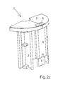
- FIG. 2 c, d the cover of the ejector tool of the injection molding tool from the contact surface
- FIG. 3 a a top view of the ejector tool from the contact surface
- FIG. 3 b a top view of the nozzle side of the injection molding tool from the contact surface.
- FIG. 1 a illustrates a typical application of the cover according to the invention, namely an actuation cover 1 ′ in the dashboard 7 of a motor vehicle.
- the actuation cover typically includes a plurality of push buttons 12 , either in rectangular form or in semicircular form within the three circular operating units which are respectively associated with backlightable functional indicators 9 .
- the functional indicators 9 are partially arranged under the push buttons 12 like for the rectangular push buttons, partially also within the push buttons 12 themselves like in the semicircular push buttons.
- the cover according to the invention can be the actuation cover 1 ′ or also one of the push buttons 12 .
- one of the semicircular push buttons is illustrated as an example for a cover 1 according to the invention, thus in FIG. 1 a , the left push button 12 according to the line B-B in a longitudinal view.
- FIGS. 1 b and 2 c, d it is illustrated in perspective views, however the principles described therein also apply for any other cover, either a rectangular push button 12 or the actuation cover 1 ′ which is not movable after the assembly.
- the cover includes the so-called front assembly which on the one hand side includes the front plate 3 which is approximately semicircular and the transparent light conductor pin 6 made from light permeable plastic material which protrudes in backward direction from the front plate 3 , wherein the light conductor pin already starts at the front side of the front plate 3 and reaches through the front plate 3 and is integrally molded with the front plate 3 in the thickness portion of the front plate 3 .
- the front plate 3 can further include protrusions 3 a which extend backward remote from the light conductor 6 , wherein the protrusions are typically integrally produced in one piece together with the front plate 3 and are made from a non-transparent material like the front plate 3 .
- the front assembly 3 + 6 is illustrated in FIG. 2 a and FIG. 2 b.
- a base element 2 is slid over the front assembly 3 + 6 from the backside, thus onto the free end of the light conductor pin 6 , wherein the base element among other things includes a sleeve 4 which has a hollow interior into which the light conductor pin 6 fits and circumferentially completely envelops the sleeve.
- the base element 2 with its sleeve 4 is pushed with the pass-through opening over the light conductor pin 6 , until the front face of the is base element 2 contacts the backside of the front plate 3 and is fixated therein, e.g. interlocked in that respective engagement lugs interlock in the interlocking openings of the protrusions 3 a of the front plate 3 .
- FIG. 1 b illustrates the finished assembly 1 in a longitudinal sectional view, thus with a slot extension in depth direction from the front plate 3 backward.
- the light conductor 6 Since the channel 5 that is open in the front and in the back in the sleeve 4 of the base element 2 has a slightly larger cross-section than the light conductor 6 , the light conductor 6 has a circumferential distance from the base element 2 .
- the light which has been introduced into the light conductor by an LED 14 which is arranged on a circuit board 13 behind the rear end of the light conductor pin 6 is conducted very well to the front end through total reflection at the side surfaces of the light conductor pin 6 and only small light components transition into the surrounding base element 2 .
- the major portion of the introduced light will be visible on the front face 6 and thus on the functional indicator 9 .
- FIGS. 3 a and 3 b describe the method of producing the cover 1 which in addition to injection molding the components also includes assembly which shall also be automatically performed in the tool.
- FIGS. 3 a and 3 b respectively illustrate the contact sides of the respective tool halves which are pressed against one another during the injection molding process and thus form cavities that are internally enclosed at all times for injecting the plastic material.
- a tool half typically the nozzle tool 102 is locally fixated in the machine.
- the liquid plastic material is injected, this means from the backside or from the sides of the tool half injection channels run to the cavities in the injection molding tool.
- the other tool half is designated as ejector tool since the cavities are positioned with respect to the contact surface between the two tool halves typically so that after opening the tool, the completely injected components remain in the extractor tool which is movably arranged in the machine and in axial direction, the depth direction 10 , the ejector tool can be placed at a distance with respect to the nozzle tool 102 .
- axially movable plungers that are included in the ejector tool 101 , wherein the plungers are arranged behind the cavities and this behind the injected work pieces are moved forward and thus eject the injected work piece out of the contact surface of the ejector tool.
- the cavities for injecting the work pieces are arranged within the form portion 8 a, b .
- the visible elements arranged outside thereof are guides and other functional elements for closing the injection molding tool 100 .
- the ejector tool 101 is pivotable back and forth or rotatable about its center axis 100 ′ in 180 degree increments and has the same cavities 105 a, b in the same arrangement and thus in two sections 100 a, b on both sides of its transversal center.
- stations A-D there is a total of four cavities, also designated as stations A-D.
- the base element 2 is injection molded in the lower section 100 b in the station A and the cavity 105 arranged therein and simultaneously the light conductor pin is injection molded adjacent thereto in the station B in the cavity 105 b.
- the cavity 105 a is positioned in axial direction 100 ′ so that after opening the tool the base element 2 remains in the ejector tool 101 , while the light conductor pin 6 remains in the nozzle tool 102 .
- the ejector tool 101 is rotated by 180 degrees about its center axis 100 ′ and subsequently the tool 100 is closed again, thus the ejector tool 101 is moved so that it contacts the nozzle tool 102 .
- the light conductor pin 6 is now disposed in station C and the front plate 3 is injection molded in the first injection molding step about the light conductor pin 6 .
- the base element 2 is now arranged in the station D and in this second step no additional machining is provided at the base element.
- a base element 2 and a light conductor pin 6 can be simultaneously injection molded again in the stations A and B.
- the tool 100 is opened again, thus the ejector tool 101 is moved at a distance to the nozzle tool 102 , wherein the finished front assembly 3 + 6 remains in the upper half in the station C of the nozzle tool 102 and is oriented with the free rear end of the light conductor pin 6 in a direction towards the ejector tool 101 .
- the base element 2 still remains and is oriented with its front face towards the nozzle tool 102 .
- the cavities 105 c , 105 d respectively provided in the two sections are respectively arranged in an individual index plate 103 which is movable forward in axial direction from the nozzle tool 102 beyond its contact surface 102 a and pivotable or rotatable by 180 degrees about the center axis 103 ′ extending in axial direction 100 ′.
- the tool 100 is opened again wherein the finished cover 1 initially remains in the station D of the ejector tool 1 and is ejected there from through an ejector which is not illustrated in more detail.
Landscapes
- Engineering & Computer Science (AREA)
- Chemical & Material Sciences (AREA)
- Combustion & Propulsion (AREA)
- Transportation (AREA)
- Mechanical Engineering (AREA)
- Injection Moulding Of Plastics Or The Like (AREA)
- Moulds For Moulding Plastics Or The Like (AREA)
- Mechanical Coupling Of Light Guides (AREA)
Applications Claiming Priority (3)
| Application Number | Priority Date | Filing Date | Title |
|---|---|---|---|
| DE102011011028A DE102011011028A1 (de) | 2011-02-11 | 2011-02-11 | Frontplatte mit darin eingespritztem Lichtleiter |
| DE102011011028.3 | 2011-02-11 | ||
| DE102011011028 | 2011-02-11 |
Publications (2)
| Publication Number | Publication Date |
|---|---|
| US20120207977A1 US20120207977A1 (en) | 2012-08-16 |
| US8999215B2 true US8999215B2 (en) | 2015-04-07 |
Family
ID=45655481
Family Applications (1)
| Application Number | Title | Priority Date | Filing Date |
|---|---|---|---|
| US13/361,596 Expired - Fee Related US8999215B2 (en) | 2011-02-11 | 2012-01-30 | Method for producing a cover |
Country Status (4)
| Country | Link |
|---|---|
| US (1) | US8999215B2 (de) |
| EP (1) | EP2487062B1 (de) |
| DE (1) | DE102011011028A1 (de) |
| PT (1) | PT2487062T (de) |
Families Citing this family (2)
| Publication number | Priority date | Publication date | Assignee | Title |
|---|---|---|---|---|
| DE102017113662A1 (de) * | 2017-06-21 | 2018-12-27 | Trw Automotive Electronics & Components Gmbh | Kraftfahrzeugbedienvorrichtung sowie Verfahren zum Herstellen einer Kraftfahrzeugbedienvorrichtung |
| CN120606509B (zh) * | 2025-07-18 | 2025-11-28 | 东莞市志迅塑胶电子有限公司 | 汽车中控插口面板盖注塑模具及注塑方法 |
Citations (8)
| Publication number | Priority date | Publication date | Assignee | Title |
|---|---|---|---|---|
| US2565803A (en) * | 1949-05-17 | 1951-08-28 | Elmer L Danielson | Method of bonding thermoplastic materials |
| US3086250A (en) * | 1957-06-21 | 1963-04-23 | Joseph A Gits | Methods of making a molded indiciabearing article |
| US3354249A (en) * | 1964-04-17 | 1967-11-21 | Coats & Clark | Method of producing united dual character parts and facing part |
| US4155972A (en) * | 1977-09-06 | 1979-05-22 | Keystone Consolidated Industries, Inc. | Multiple-shot method of molding plastic products |
| US4440820A (en) * | 1980-12-24 | 1984-04-03 | Fujitsu Limited | Plastic molding |
| US5469758A (en) * | 1993-11-03 | 1995-11-28 | The Grigoleit Company | Knob with soft plastic cover |
| US6133248A (en) * | 1997-06-13 | 2000-10-17 | Cydex, Inc. | Polar drug of prodrug compositions with extended shelf-life storage and a method of making thereof |
| US6391243B1 (en) * | 1996-01-05 | 2002-05-21 | The Grigoleit Company | Method for manufacturing an indicator knob |
Family Cites Families (3)
| Publication number | Priority date | Publication date | Assignee | Title |
|---|---|---|---|---|
| FR2611578B1 (fr) * | 1987-02-26 | 1989-09-08 | Macrez Guy | Organe conducteur de lumiere, procede et moule pour sa fabrication |
| DE59206715D1 (de) * | 1992-09-25 | 1996-08-08 | Valeo Klimasysteme Gmbh | Anzeigevorrichtung, insbesondere Frontblende eines Kraftfahrzeug-Bediengerätes |
| AT5441U1 (de) * | 2001-07-27 | 2002-07-25 | Engel Gmbh Maschbau | Verfahren zur herstellung eines kunststoffkörpers |
-
2011
- 2011-02-11 DE DE102011011028A patent/DE102011011028A1/de not_active Withdrawn
-
2012
- 2012-01-30 US US13/361,596 patent/US8999215B2/en not_active Expired - Fee Related
- 2012-02-09 PT PT12154596T patent/PT2487062T/pt unknown
- 2012-02-09 EP EP12154596.6A patent/EP2487062B1/de not_active Not-in-force
Patent Citations (10)
| Publication number | Priority date | Publication date | Assignee | Title |
|---|---|---|---|---|
| US2565803A (en) * | 1949-05-17 | 1951-08-28 | Elmer L Danielson | Method of bonding thermoplastic materials |
| US3086250A (en) * | 1957-06-21 | 1963-04-23 | Joseph A Gits | Methods of making a molded indiciabearing article |
| US3354249A (en) * | 1964-04-17 | 1967-11-21 | Coats & Clark | Method of producing united dual character parts and facing part |
| US4155972A (en) * | 1977-09-06 | 1979-05-22 | Keystone Consolidated Industries, Inc. | Multiple-shot method of molding plastic products |
| US4440820A (en) * | 1980-12-24 | 1984-04-03 | Fujitsu Limited | Plastic molding |
| US5469758A (en) * | 1993-11-03 | 1995-11-28 | The Grigoleit Company | Knob with soft plastic cover |
| US5688461A (en) * | 1993-11-03 | 1997-11-18 | The Grigoleit Company | Method of molding a composite plastic article |
| US6391243B1 (en) * | 1996-01-05 | 2002-05-21 | The Grigoleit Company | Method for manufacturing an indicator knob |
| US6568036B1 (en) * | 1996-01-05 | 2003-05-27 | The Grigoleit Company | Composite indicator knob and a method for manufacturing a knob |
| US6133248A (en) * | 1997-06-13 | 2000-10-17 | Cydex, Inc. | Polar drug of prodrug compositions with extended shelf-life storage and a method of making thereof |
Also Published As
| Publication number | Publication date |
|---|---|
| PT2487062T (pt) | 2018-10-10 |
| DE102011011028A1 (de) | 2012-08-16 |
| EP2487062A3 (de) | 2014-11-26 |
| EP2487062A2 (de) | 2012-08-15 |
| EP2487062B1 (de) | 2018-06-20 |
| US20120207977A1 (en) | 2012-08-16 |
Similar Documents
| Publication | Publication Date | Title |
|---|---|---|
| US8999214B2 (en) | Multi K-tool with assembly | |
| JP4602869B2 (ja) | 複合成形品の成形方法とそれに用いる型締装置 | |
| US6428730B1 (en) | Method for manufacturing synthetic resin-made hollow member with intermediate element incorporated therein, and apparatus therefor | |
| US4416602A (en) | Injection molding apparatus for manufacturing articles from different types of plastic material | |
| EP2185335B1 (de) | Spritzgussverfahren und spritzgussform | |
| US10751921B2 (en) | Receiving device and injection-molding method | |
| US8999215B2 (en) | Method for producing a cover | |
| US7914054B2 (en) | Vehicle latch and method of manufacturing the same | |
| KR101736777B1 (ko) | 차량 아웃사이드 도어 핸들 스위치 러버 제조를 위한 사출물 인서트용 지그 장치 | |
| KR102149026B1 (ko) | 상하측 동시성형이 가능한 2단 슬라이딩 코어가 장착된 이중사출금형 | |
| JP3794236B2 (ja) | 型内組み立て装置及びそれを用いたギヤポンプの製造方法 | |
| KR101487010B1 (ko) | 횡축 및 종축 회전하는 멀티 사출금형 및 이를 이용한 사출물의 사출방법 | |
| JP3092488B2 (ja) | 樹脂成形品の製造方法およびその製造用金型 | |
| CN115816775B (zh) | 成型模具 | |
| GB2276583A (en) | Plastic moulding apparatus | |
| KR101861565B1 (ko) | 사출 성형장치 | |
| US7938638B2 (en) | Mould for the injection-moulding a component comprising two portions which are composed of different materials | |
| CA2079441A1 (en) | Method of manufacturing components of plastics enclosures and apparatus for use in the method | |
| US7364683B2 (en) | Rotary automatic transfer rail for injection molding | |
| KR102817995B1 (ko) | 글레이징 및 인서트 오버몰딩 장치 및 방법, 그 장치 및 그 방법에 사용되는 인서트 | |
| JP4880045B2 (ja) | 複合成形用の型締装置及び複合成形品の成形方法 | |
| JP4649119B2 (ja) | 射出成形用金型 | |
| CN210651685U (zh) | 一种车载cd面板的成型模具 | |
| JP3694695B1 (ja) | 複合連結長尺物の成形金型 | |
| JP6318766B2 (ja) | 積層成形用射出成形機及び射出成形方法 |
Legal Events
| Date | Code | Title | Description |
|---|---|---|---|
| AS | Assignment |
Owner name: DITTER PLASTIC GMBH + CO. KG, GERMANY Free format text: ASSIGNMENT OF ASSIGNORS INTEREST;ASSIGNOR:DITTER, ROLF PETER;REEL/FRAME:027619/0563 Effective date: 20120113 |
|
| STCF | Information on status: patent grant |
Free format text: PATENTED CASE |
|
| MAFP | Maintenance fee payment |
Free format text: PAYMENT OF MAINTENANCE FEE, 4TH YR, SMALL ENTITY (ORIGINAL EVENT CODE: M2551); ENTITY STATUS OF PATENT OWNER: SMALL ENTITY Year of fee payment: 4 |
|
| FEPP | Fee payment procedure |
Free format text: MAINTENANCE FEE REMINDER MAILED (ORIGINAL EVENT CODE: REM.); ENTITY STATUS OF PATENT OWNER: SMALL ENTITY |
|
| LAPS | Lapse for failure to pay maintenance fees |
Free format text: PATENT EXPIRED FOR FAILURE TO PAY MAINTENANCE FEES (ORIGINAL EVENT CODE: EXP.); ENTITY STATUS OF PATENT OWNER: SMALL ENTITY |
|
| STCH | Information on status: patent discontinuation |
Free format text: PATENT EXPIRED DUE TO NONPAYMENT OF MAINTENANCE FEES UNDER 37 CFR 1.362 |
|
| FP | Lapsed due to failure to pay maintenance fee |
Effective date: 20230407 |