US8994953B2 - Phased based sensing - Google Patents
Phased based sensing Download PDFInfo
- Publication number
- US8994953B2 US8994953B2 US13/060,546 US200913060546A US8994953B2 US 8994953 B2 US8994953 B2 US 8994953B2 US 200913060546 A US200913060546 A US 200913060546A US 8994953 B2 US8994953 B2 US 8994953B2
- Authority
- US
- United States
- Prior art keywords
- signal
- transducer
- phase
- frequency
- delayed
- Prior art date
- Legal status (The legal status is an assumption and is not a legal conclusion. Google has not performed a legal analysis and makes no representation as to the accuracy of the status listed.)
- Active, expires
Links
- 230000008859 change Effects 0.000 claims abstract description 20
- 238000000034 method Methods 0.000 claims description 33
- 230000003111 delayed effect Effects 0.000 claims description 26
- 239000000835 fiber Substances 0.000 claims description 25
- 230000004044 response Effects 0.000 claims description 7
- 230000035945 sensitivity Effects 0.000 abstract description 10
- 238000005259 measurement Methods 0.000 abstract description 6
- 230000000694 effects Effects 0.000 abstract description 4
- 230000002452 interceptive effect Effects 0.000 abstract description 2
- 230000003287 optical effect Effects 0.000 description 12
- 238000005070 sampling Methods 0.000 description 6
- 238000000926 separation method Methods 0.000 description 6
- 239000013307 optical fiber Substances 0.000 description 4
- 238000003491 array Methods 0.000 description 3
- 230000003247 decreasing effect Effects 0.000 description 2
- 230000001934 delay Effects 0.000 description 2
- 230000001419 dependent effect Effects 0.000 description 2
- 238000000605 extraction Methods 0.000 description 2
- 230000002238 attenuated effect Effects 0.000 description 1
- 230000008901 benefit Effects 0.000 description 1
- 230000015572 biosynthetic process Effects 0.000 description 1
- 230000008602 contraction Effects 0.000 description 1
- 238000001514 detection method Methods 0.000 description 1
- 238000010304 firing Methods 0.000 description 1
- 238000005755 formation reaction Methods 0.000 description 1
- 230000004048 modification Effects 0.000 description 1
- 238000012986 modification Methods 0.000 description 1
- 230000008569 process Effects 0.000 description 1
- 230000000644 propagated effect Effects 0.000 description 1
Images


Classifications
-
- G—PHYSICS
- G01—MEASURING; TESTING
- G01D—MEASURING NOT SPECIALLY ADAPTED FOR A SPECIFIC VARIABLE; ARRANGEMENTS FOR MEASURING TWO OR MORE VARIABLES NOT COVERED IN A SINGLE OTHER SUBCLASS; TARIFF METERING APPARATUS; MEASURING OR TESTING NOT OTHERWISE PROVIDED FOR
- G01D5/00—Mechanical means for transferring the output of a sensing member; Means for converting the output of a sensing member to another variable where the form or nature of the sensing member does not constrain the means for converting; Transducers not specially adapted for a specific variable
- G01D5/26—Mechanical means for transferring the output of a sensing member; Means for converting the output of a sensing member to another variable where the form or nature of the sensing member does not constrain the means for converting; Transducers not specially adapted for a specific variable characterised by optical transfer means, i.e. using infrared, visible, or ultraviolet light
- G01D5/32—Mechanical means for transferring the output of a sensing member; Means for converting the output of a sensing member to another variable where the form or nature of the sensing member does not constrain the means for converting; Transducers not specially adapted for a specific variable characterised by optical transfer means, i.e. using infrared, visible, or ultraviolet light with attenuation or whole or partial obturation of beams of light
- G01D5/34—Mechanical means for transferring the output of a sensing member; Means for converting the output of a sensing member to another variable where the form or nature of the sensing member does not constrain the means for converting; Transducers not specially adapted for a specific variable characterised by optical transfer means, i.e. using infrared, visible, or ultraviolet light with attenuation or whole or partial obturation of beams of light the beams of light being detected by photocells
- G01D5/353—Mechanical means for transferring the output of a sensing member; Means for converting the output of a sensing member to another variable where the form or nature of the sensing member does not constrain the means for converting; Transducers not specially adapted for a specific variable characterised by optical transfer means, i.e. using infrared, visible, or ultraviolet light with attenuation or whole or partial obturation of beams of light the beams of light being detected by photocells influencing the transmission properties of an optical fibre
- G01D5/35303—Mechanical means for transferring the output of a sensing member; Means for converting the output of a sensing member to another variable where the form or nature of the sensing member does not constrain the means for converting; Transducers not specially adapted for a specific variable characterised by optical transfer means, i.e. using infrared, visible, or ultraviolet light with attenuation or whole or partial obturation of beams of light the beams of light being detected by photocells influencing the transmission properties of an optical fibre using a reference fibre, e.g. interferometric devices
-
- G—PHYSICS
- G01—MEASURING; TESTING
- G01V—GEOPHYSICS; GRAVITATIONAL MEASUREMENTS; DETECTING MASSES OR OBJECTS; TAGS
- G01V1/00—Seismology; Seismic or acoustic prospecting or detecting
- G01V1/16—Receiving elements for seismic signals; Arrangements or adaptations of receiving elements
Definitions
- the present invention relates to sensors which exploit a change in phase of an interrogation signal to determine a sensed parameter, and particularly, but not exclusively to fibre optic interferometric sensing.
- the present invention finds particular application in the field of seismic surveying.
- Certain types of fibre optic sensors employ a length of optic fibre arranged in such a way that a sensed parameter causes a strain to be imposed on the fibre.
- the fibre is arranged in a coil, although other arrangements are possible.
- Such strain causes a change in phase of optical signal propagation in that fibre, which change can be detected by interferometric techniques.
- a variety of different arrangements for this type of transducer have previously been proposed, many of which have the coil of optic fibre wound on a deformable core or mandrel, which undergoes radial expansion or contraction in response to the sensed parameter, such as sensed vibration.
- Such fibre optic sensors can exhibit extremely high sensitivities, and have the advantage of being completely passive, employing no power at the sensing transducer.
- Such sensors have also proved popular in applications where large arrays of sensors are required, on account of the relative ease with which they can be multiplexed.
- An example of such an application is seismic surveying in the oil and gas exploration industry, where large time multiplexed arrays comprising hundreds or even thousands of vibration sensors and/or hydrophones can be used to sense reflections of an incident pulse from geological formations beneath the sea bed. Sampling such an array at regular periods provides 3D time lapsed data on existing or potential new reserves.
- a high amplitude seismic source (usually an airgun) is towed across the top of a known or potential oilfield, firing the source at regular intervals, and the reflected returns form the source are monitored using sensors which are either towed together with the source or are positioned on the seabed. It is desired to be able to measure directly both the direct signal from the airgun when it first hits the sensors, and the seismic returns reflected from the underground features within the field, which have significantly lower amplitudes.
- Applicant's co-pending International patent application No. PCT/GB2008/000830 describes apparatus and techniques for determining the derivative of the phase with respect to time which is imposed by a transducer (or a mulitiplexed array of transducers) on an interrogating signal. This technique is referred to as the derivative sensor technique (DST).
- DST derivative sensor technique
- the rate of change, or derivative of the phase typically has a much smaller amplitude than the signal itself since the difference between the two times at which the signal is measured will usually be much less than the period of the signal being measured.
- DST provides a reduced sensitivity measurement.
- the derivative of that signal will typically be attenuated by at least 60 dB with a period between the two measurement times of 200 ns.
- PCT/GB2008/000830 describes multiple means of generating derivative signals with different amplitudes by using a different optical return methods and architecture, employing optical pulse pairs with different separations, where the length of separation determines the amplitude of the channel. This can result in derivative outputs with levels which are approximately 50 dB lower at 800 Hz (described as “medium DST”) and 38 dB lower at 800 Hz (described as “long DST”)
- the level of the derivative signal is proportional to the difference in time between when the pulses pass through the sensor. Decreasing this time difference reduces the level of the derivative signal but increases the maximum level of the dynamic signal that can be measured. There is a practical limit, however, on the minimum time difference between pulse pairs in the multiplexed arrays described above.
- a method of interrogating a phase based transducer said transducer providing a change in phase of signal propagation in response to a sensed parameter, said method comprising receiving a single pulse signal frequency propagated through said transducer; combining a delayed version and an undelayed version of the single pulse signal; and determining from said combination a measure of the rate of change of phase with time of said signal.
- the level of the derivative signal is proportional to the difference in time between when the pulses pass through the sensor. Decreasing this time difference reduces the level of the derivative signal but increases the maximum level of the dynamic signal that can be measured. Thus to measure very large dynamic signals it will be necessary to have a very short time separation.
- a pulse pair is input to an array, and the time separation between the pulses can determine the level of sensitivity which results.
- the optical pulses have a minimum width which is of the order of 100 ns. Therefore the minimum time difference between pulses is also 100 ns otherwise an output interferometer can not be used to realign the two pulses.
- the received signal can be combined with a version having been delayed by only a very short duration, and delays of less than 100 ns or less than 50 ns are achievable. In the example described below delays of 10 ns or less are used.
- the received signal is a substantially square wave pulse in a typical embodiment.
- the pulse may be part of a train of pulses for example, but each received pulse can be delayed by a small amount such that it temporally overlaps with the undelayed version with which it is combined. In other words, the delay is less than the pulse duration, such that temporally misaligned versions of the same pulse are combined.
- the pulse will comprise a single frequency.
- the frequency of the delayed version is shifted relative to the frequency of the undelayed version in embodiments.
- differing frequency shifts can be imposed on the signals in the respective arms of the interferometer.
- the actual value of the sensed parameter can be reconstructed by integrating the measured derivative value.
- the noise floor is determined by system noise, then the noise floor is substantially the same for both the phase information and its derivative, the derivative signal suffers from a lower SNR.
- overloading occurs when the instantaneous frequency of the output of the transducer (which depends on the rate of change of phase) falls outside of the Nyquist frequency range determined by the rate at which this signal is sampled. Any instantaneous frequency that falls outside the Nyquist range will be folded about the limits of the range back into it. Depending on the amplitude and frequency of the sensed signal, the information may be folded or wrapped about the Nyquist frequency limits multiple times. The present inventors have found that the derivative information measured in embodiments of the present information can be used to determine how many times the information has been wrapped, or the factor by which the information exceeds the Nyquist limit. This then allows the directly measured parameter value to be corrected to provide a signal having an improved SNR to that provided by integrating the measured derivative signal.
- FIG. 1 shows a known type of fibre optic sensor package
- FIG. 2 is an interrogating waveform suitable for the package of FIG. 1 ;
- FIG. 3 illustrates a typical response from a package of the type shown in FIG. 1 ;
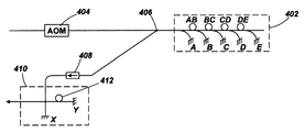
- FIG. 4 shows a system for interrogating a fibre optic package according to an aspect of the invention
- FIG. 5 illustrates an output obtainable from the system of FIG. 4 ;
- FIG. 6 shows an arrangement according to an embodiment of the invention
- FIG. 7 illustrates the output of the arrangement of FIG. 6 ;
- FIG. 8 shows an arrangement according to a further embodiment of the invention.
- FIG. 9 illustrates an arrangement capable of producing multiple outputs
- FIG. 10 illustrates the function of part of the system of FIG. 9 .
- FIG. 1 there is shown schematically a known type of fibre-optic sensor package, indicated generally 102 , comprising four individual fibre-optic sensing coils 104 , 106 , 108 , 110 formed from a single length of optical fibre 13 , and arranged in series. A portion of the optical fibre 112 serves as the package input/output (i/o) fibre. Fibre-coupled mirrors 114 , 116 , 118 , 120 , 122 are coupled to the optical fibre 13 at respective locations along it such that each of the coils has a fibre-coupled-mirror coupled at each end of it.
- Fibre-coupled mirrors 114 , 116 , 118 , 120 , 122 are coupled to the optical fibre 13 at respective locations along it such that each of the coils has a fibre-coupled-mirror coupled at each end of it.
- fibre Bragg gratings Other means of reflecting a portion of light from before and after each sensor such as in fibre Bragg gratings could be used instead of the fibre coupled mirrors.
- a large scale array of such packages can be coupled together, and interrogated periodically using multiplexing to provide time lapsed seismic imagery for example.
- an interrogation of the package 102 of FIG. 1 may be carried out by introducing a pair of interrogating optical pulses 202 , 204 into the package i/o fibre 112 .
- FIG. 3 illustrates the optical output response of the package by considering the output formed by each of the pair of input pulses.
- the first pulse 202 to arrive at the package is reflected off each of the 5 fibre-coupled mirrors to produce five output pulses 301 , 302 , 303 , 304 and 305 , measured relative to an arbitrary time reference.
- pulse 204 produces five time delayed output pulses 322 , 323 , 324 , 325 and 326 relative to the same arbitrary time reference.
- pulses 331 , 332 , 333 , 334 , 335 and 336 shown in FIG. 3 c .
- pulses 332 to 335 correspond to the combination of a pulse which has passed (twice) through the coil between the two adjacent mirrors, and a pulse which has not.
- the pulses which are combined have different frequencies, by virtue of the input pulses 202 and 204 having different frequencies.
- the effect of the frequency difference between the pulses which are combined is the generation of a carrier frequency onto which phase information is modulated. Phase detection can therefore be used to determine the phase change imposed by that coil, and hence a measure of the sensed parameter is obtained as is known in the art.
- the signal obtained from a photodetector used to measure a series of pulses returning from a sensor of the type described above can be written as cos( ⁇ c t+ ⁇ (t)) i.e. the sensed information is represented as a phase change superimposed on a carrier signal of frequency ⁇ c .
- Techniques that are well known to those skilled in the art can then be used to demodulate the phase signal from the carrier.
- the carrier frequency is typically chosen to be half of the Nyquist frequency, which is in turn half of the sampling frequency. It is usual for one sample to be made in each returning optical pulse and so the sampling frequency is the rate at which pulse pairs are transmitted into the array.
- the sampling frequency could be approximately 320 kHz, giving a Nyquist frequency of approximately 160 kHz and a carrier frequency of approximately 80 kHz.
- the sampling frequency will typically have a practical upper limit dependent upon the type and arrangement of sensor or sensors, amongst other factors.
- An overscale condition occurs when the instantaneous frequency of the phase modulated carrier falls outside the Nyquist band i.e. when
- FIG. 4 illustrates interrogation of a sensor package as described in PCT/GB2008/000830.
- the package 402 is interrogated by a pair of pulses produced by acousto-optic modulator 404 .
- the output series of pulses is tapped off at junction 406 , passed through an isolator 408 , and to a phase detector such as an output interferometer designated by 410 .
- the delay between input pulses is arranged to be twice the time of flight of light through delay coil 412 of the output interferometer. While the described embodiment employs a Michelson interferometer, the skilled reader would recognise that a Mach-Zehnder type interferometer with a delay coil in one of the arms could equally be used. In this case, arranging for the separation between the input pulses to be just the time of flight through the delay coil in one arm of the interferometer would allow equivalent measurements to be made.
- FIG. 5 illustrates component pulse trains output from interferometer 410 .
- Pulse train 502 represents the output of the leading input pulse (designated by subscript 1 ) from mirrors B to E, resulting from the delay arm of the interferometer (designated Y).
- Pulse train 504 represents the output from the lagging input pulse (designated by subscript 2 ) from mirrors B to E, resulting from the undelayed arm of the interferometer (designated X) It can be seen that, in this way, interferometer 410 temporally aligns and interferes pairs of pulses, both of which have passed through the same sensing coil(s) of package 402 , but at different times.
- each pulse reflected off fibre coupled mirrors B to E pulse reflected off mirror A have not passed through a sensing coil), and gathering information on the associated sensing coil, is combined with a pulse having undergone the same optical path, gathering the same information, but at a later time.
- the alignment of pulses is such that one of each combined pair is a reflection from a leading input pulse (subscript 1 ), and the other from the lagging input pulse (subscript 2 ).
- the pulses in a pair have a frequency difference which, as noted above, causes phase to be modulated onto a carrier signal.
- the output of the interferometer therefore represents the derivative of the phase value, in contrast to the actual value of phase which would usually be measured directly.
- the system depicted in FIG. 4 derives a value representative of
- the derivative value is extracted from this pulse then, by subtracting the derivative value of sensing loop AB (obtained above) the derivative value of sensing loop BC is obtained. In this way, the derivative values for each of the sensing loops in package 402 can be obtained.
- a single pulse returning from a transducer or transducer array passes through an isolator 602 and enters an output interferometer generally designated 604 .
- a delay 606 in one arm of the interferometer creates a version of the pulse which is delayed by an amount less than the pulse duration. This delayed version is combined with an undelayed version (from the other arm of the interferometer) in the interferometer and resulting signal is output at 608 for demodulation.
- FIG. 7 illustrates the effect of the apparatus of FIG. 6 .
- An input pulse of 100 ns duration is taken as an example.
- a suitable interferometer delay for such a pulse is approximately 10 ns which can be achieved with a 1 m delay coil.
- the pulse produced by the undelayed arm of the interferometer is shown at 702 , and the corresponding delayed pulse at 704 . It can be seen that because the delay is less than the pulse duration, the pulses overlap in time. If we consider a measurement made of the interference between the two pulses at a time t, it will be understood that the sampled portion of the delayed pulse will have passed through the transducer 10 ns before the sampled portion of the undelayed equivalent with which it now interferes.
- phase is captured by the interference of two pulses having a slight frequency difference, typically about 50 kHz.
- this frequency difference causes a carrier signal to be generated which the dynamic signal then modulates, making it easier to extract the dynamic signal.
- the two interfering pulses have the same frequency because they are versions of a single pulse having only a single frequency. There is therefore no carrier signal, making extraction of the dynamic signal more difficult.
- FIG. 8 illustrates an arrangement which addresses this difficulty.
- Output interferometer 804 includes acousto-optic modulators (AOMs) 810 and 812 in both arms.
- AOMs acousto-optic modulators
- One of the AOMs is driven by a continuous RF signal at f 1 while the other is driven at f 2 .
- Each time the light passes through an AOM its frequency is shifted by the RF drive frequency.
- the level of the derivative signal is proportional to the difference in time between when the pulses pass through the sensor.
- a derivative signal will be generated based on a time delay of 10 ns which is shorter than the minimum value that is practicably achievable with the derivative technique described above with reference to FIGS. 4 and 5 . Consequently a larger dynamic signal can be measured. It would be possible to measure still larger signals by reducing the path difference of 1 m, and hence the delay, to a smaller value.
- embodiments of the present invention will experience reduced SNR, which will be particularly low when the normal signal is only just over loaded.
- Direct reconstruction of the normal signal (as described in PCT/GB2008/000830 for example) may then be problematic, and so the arrangement of FIG. 9 is proposed.
- the system of FIG. 9 is adapted to receive the output from a series of sensors each sensing coil comprising 40 m of optical fibre. In this case a double pass of light through each sensor will take approx 400 ns. A series of pairs of optical pulses at frequencies that differ by 50 kHz are transmitted into the array, with the separation of the two pulses in a pair being 200 ns. Light returning from the sensors is split at splitter 902 . One half of the returning light passes to interferometer 904 which includes a 20 m ( ⁇ 200 ns) path imbalance 905 , and is subsequently output to photodetector 906 to measure both the normal and standard derivative signals.
- Interferometer 904 operates as described in PCT/GB2008/000830 to produce pulse trains as illustrated in FIG. 10 (with notation X and Y referring to the undelayed and delayed arms of the interferometer respectively).
- Reflections from the same reflector (denoted A, B . . . ) of the transducer package of the leading and lagging (denoted subscript 1 and 2 ) pulse are aligned and interfered, in substantially the same way as described with reference to FIG. 5 , as seen from pulse trains 1004 and 1006 .
- This therefore provides derivative or ‘low sensitivity’ information for each sensor coil (cumulatively).
- reflections from adjacent reflectors of the package of leading and lagging pulses are aligned and interfered as seen from pulse trains 1002 and 1008 which are essentially of the same form as shown in FIG. 3 , and combine to form output pulses carrying the direct or ‘high sensitivity’ parameter values.
- Interferometer 904 therefore produces an output having two different sensitivities in the form of interleaved pulse trains. Pulses having a frequency difference are interfered such that the sensed information is modulated onto a 50 Hz carrier and can be extracted directly in the known fashion.
- interferometer 908 which contains two AOMs 912 and 914 and a 1 m path imbalance 916 substantially as described with respect to FIG. 6 , and then onto photodetector 910 .
- interferometer 908 Before passing through any interferometer the reflections from the two optical pulses in a pair do not overlap and so they can be treated as a single return pulse, and interferometer 908 functions as described previously to produce ‘very low sensitivity’ derivative phase modulated onto a 50 Hz carrier.
- the arrangement of FIG. 9 produces 3 outputs representing a parameters sensed by the same transducer package, but all having different sensitivities, which enables a very wide range of signal amplitudes to be measured. This result is achieved from a single interrogating waveform comprising a pair of time spaced pulses.
- fibre optic sensor package suitable for seismic surveying has been described, it will be appreciated by the skilled person that the invention is equally applicable to other types of phase based transducers employed in alternative applications. Examples include uses of fibre optic hydrophones in active sonar systems and measurements of surface vibration using a free space optical interferometer.
Applications Claiming Priority (3)
| Application Number | Priority Date | Filing Date | Title |
|---|---|---|---|
| GB0815523.6 | 2008-08-27 | ||
| GB0815523A GB0815523D0 (en) | 2008-08-27 | 2008-08-27 | Phase based sensing |
| PCT/GB2009/002035 WO2010023434A2 (en) | 2008-08-27 | 2009-08-20 | Phase based sensing |
Publications (2)
| Publication Number | Publication Date |
|---|---|
| US20110149295A1 US20110149295A1 (en) | 2011-06-23 |
| US8994953B2 true US8994953B2 (en) | 2015-03-31 |
Family
ID=39846817
Family Applications (1)
| Application Number | Title | Priority Date | Filing Date |
|---|---|---|---|
| US13/060,546 Active 2030-03-02 US8994953B2 (en) | 2008-08-27 | 2009-08-20 | Phased based sensing |
Country Status (7)
| Country | Link |
|---|---|
| US (1) | US8994953B2 (zh) |
| EP (1) | EP2329226B1 (zh) |
| JP (1) | JP5628174B2 (zh) |
| CN (1) | CN102216737B (zh) |
| GB (1) | GB0815523D0 (zh) |
| NO (1) | NO2329226T3 (zh) |
| WO (1) | WO2010023434A2 (zh) |
Cited By (2)
| Publication number | Priority date | Publication date | Assignee | Title |
|---|---|---|---|---|
| US20180356210A1 (en) * | 2017-06-08 | 2018-12-13 | Hifi Engineering Inc. | Optical interrogator for performing interferometry using fiber bragg gratings |
| US10416005B2 (en) | 2014-12-04 | 2019-09-17 | Hifi Engineering Inc. | Optical interrogator for performing interferometry using fiber Bragg gratings |
Families Citing this family (11)
| Publication number | Priority date | Publication date | Assignee | Title |
|---|---|---|---|---|
| GB0705240D0 (en) * | 2007-03-14 | 2007-04-25 | Qinetiq Ltd | Phase based sensing |
| GB0810977D0 (en) * | 2008-06-16 | 2008-07-23 | Qinetiq Ltd | Phase based sensing |
| GB0917150D0 (en) | 2009-09-30 | 2009-11-11 | Qinetiq Ltd | Phase based sensing |
| GB2488841B (en) | 2011-03-11 | 2014-09-10 | Tgs Geophysical Company Uk Ltd | Sensor array |
| GB2489749B (en) * | 2011-04-08 | 2016-01-20 | Optasense Holdings Ltd | Fibre optic distributed sensing |
| CN102997047A (zh) * | 2011-09-14 | 2013-03-27 | 中国石油天然气集团公司 | 一种天然气管道泄漏光纤监测传感器的复用/解复用系统 |
| US9234790B2 (en) * | 2012-03-19 | 2016-01-12 | The Board Of Trustees Of The Leland Stanford Junior University | Apparatus and methods utilizing optical sensors operating in the reflection mode |
| RU2562689C1 (ru) * | 2014-06-02 | 2015-09-10 | Общество с ограниченной ответственностью "Научно-технический центр Т8" (ООО "Т8 НТЦ") | Распределенный датчик акустических и вибрационных воздействий |
| US20190003879A1 (en) * | 2015-12-08 | 2019-01-03 | Hawk Measurement Systems Pty. Ltd. | Improved optical fiber sensing system |
| CN110365415B (zh) * | 2019-08-01 | 2020-10-20 | 浙江大学 | 一种基于光纤光栅传感器阵列的调频解调装置 |
| CN116989832B (zh) * | 2023-09-26 | 2023-12-26 | 北京大学 | 一种可变多空间传感尺度地震勘探方法及系统 |
Citations (32)
| Publication number | Priority date | Publication date | Assignee | Title |
|---|---|---|---|---|
| US4121155A (en) | 1976-12-02 | 1978-10-17 | The Charles Stark Draper Laboratory, Inc. | Position readout device |
| US4231260A (en) | 1978-11-03 | 1980-11-04 | The Charles Stark Draper Laboratory, Inc. | Position determining system |
| US4649529A (en) * | 1985-12-02 | 1987-03-10 | Exxon Production Research Co. | Multi-channel fiber optic sensor system |
| US4697926A (en) * | 1985-02-08 | 1987-10-06 | The Board Of Trustees Of The Leland Stanford Junior University | Coherent distributed sensor and method using short coherence length sources |
| US4699513A (en) | 1985-02-08 | 1987-10-13 | Stanford University | Distributed sensor and method using coherence multiplexing of fiber-optic interferometric sensors |
| WO1987006690A1 (en) | 1986-04-22 | 1987-11-05 | Plessey Overseas Limited | Improvements relating to optical fibre sensing systems |
| US4770535A (en) | 1985-02-08 | 1988-09-13 | The Board Of Trustees Of The Leland Stanford Junior University | Distributed sensor array and method using a pulsed signal source |
| US4848906A (en) | 1987-02-02 | 1989-07-18 | Litton Systems, Inc. | Multiplexed fiber optic sensor |
| US4947037A (en) | 1988-06-14 | 1990-08-07 | Plessey Overseas Limited | Optical sensing system with light pulses |
| US5039221A (en) * | 1989-07-03 | 1991-08-13 | Litton Systems, Inc. | Interferometer calibration for fiber optic sensor arrays |
| US5140154A (en) | 1991-01-16 | 1992-08-18 | The United States Of America As Represented By The Secretary Of The Navy | Inline fiber optic sensor arrays with delay elements coupled between sensor units |
| US5412474A (en) * | 1992-05-08 | 1995-05-02 | Smithsonian Institution | System for measuring distance between two points using a variable frequency coherent source |
| US5680489A (en) | 1996-06-28 | 1997-10-21 | The United States Of America As Represented By The Secretary Of The Navy | Optical sensor system utilizing bragg grating sensors |
| US5787053A (en) * | 1989-07-07 | 1998-07-28 | The United States Of America As Represented By The Secretary Of The Navy | Continuous fiber pulse reflecting means |
| WO2000012977A1 (en) | 1998-09-01 | 2000-03-09 | Input/Output, Inc. | Seismic optical acoustic recursive sensor system |
| US6449046B1 (en) | 1999-05-17 | 2002-09-10 | Chung-Shan Institute Of Science And Technology | Optically amplified WDM/TDM hybrid polarization-insensitive fiber-optic interferometric sensor system |
| US6466706B1 (en) | 2000-10-11 | 2002-10-15 | The United States Of America As Represented By The Secretary Of The Navy | Pulsed system and method for fiber optic sensor |
| US6785004B2 (en) * | 2000-11-29 | 2004-08-31 | Weatherford/Lamb, Inc. | Method and apparatus for interrogating fiber optic sensors |
| US20050078316A1 (en) | 2003-10-10 | 2005-04-14 | Erlend Ronnekleiv | Active coherence reduction for interferometer interrogation |
| WO2006048647A2 (en) | 2004-11-03 | 2006-05-11 | Polarmetrix Limited | Detecting a disturbance in the propagation of light in an optical waveguide |
| US7072566B2 (en) * | 2003-06-26 | 2006-07-04 | Ricoh Company, Ltd. | Ultrashort-pulse laser-working method and apparatus and structural bodies produced by using the same |
| US7119325B2 (en) | 2003-01-27 | 2006-10-10 | Bookham Technology Plc | System and method for monitoring environmental effects using optical sensors |
| US20070024857A1 (en) * | 2005-07-28 | 2007-02-01 | Sercel | Fiber optic interferometric sensor array |
| US20070041020A1 (en) | 2005-08-17 | 2007-02-22 | Hall David B | Method and apparatus for direct detection of signals from a differential delay heterodyne interferometric system |
| US20070097377A1 (en) * | 2005-11-01 | 2007-05-03 | Courville Carol J | System and method for generating beams of light using an anisotropic acousto-optic modulator |
| US20070097376A1 (en) * | 2005-11-01 | 2007-05-03 | Courville Carol J | System and method for generating beams of light using an anisotropic acousto-optic modulator |
| GB2442745A (en) | 2006-10-13 | 2008-04-16 | At & T Corp | Acoustic sensing using an optical fibre |
| US7424191B2 (en) | 2003-04-28 | 2008-09-09 | The Furukawa Electric Co., Ltd. | System for measuring the wavelength dispersion and nonlinear coefficient of an optical fiber |
| WO2008110780A2 (en) | 2007-03-14 | 2008-09-18 | Qinetiq Limited | Phase based sensing |
| US20080277568A1 (en) | 2005-10-25 | 2008-11-13 | Qinetiq Limited | Traffic Sensing and Monitoring Apparatus |
| US20080291461A1 (en) * | 2005-02-11 | 2008-11-27 | Ole Henrik Waagaard | Method and apparatus for suppression of crosstalk and noise in time-division multiplexed interferometric sensor systems |
| WO2010004249A2 (en) | 2008-06-16 | 2010-01-14 | Qinetiq Limited | Phase based sensing |
Family Cites Families (6)
| Publication number | Priority date | Publication date | Assignee | Title |
|---|---|---|---|---|
| JPH09304169A (ja) * | 1996-05-10 | 1997-11-28 | Oki Electric Ind Co Ltd | 光ファイバ加速度センサ |
| CN1207169A (zh) * | 1996-11-15 | 1999-02-03 | 利顿系统有限公司 | 传感方法和装置 |
| JP2001045082A (ja) * | 1999-07-28 | 2001-02-16 | Matsushita Electric Ind Co Ltd | 周波数オフセット量検出装置 |
| CN100353172C (zh) * | 2002-09-17 | 2007-12-05 | 联发科技股份有限公司 | 群延迟测试方法及装置 |
| GB2436872A (en) * | 2006-04-06 | 2007-10-10 | Qinetiq Ltd | Fibre-optic sensor package |
| GB0713413D0 (en) * | 2007-07-11 | 2007-08-22 | Qinetiq Ltd | Phased based sensing |
-
2008
- 2008-08-27 GB GB0815523A patent/GB0815523D0/en not_active Ceased
-
2009
- 2009-08-20 EP EP09784972.3A patent/EP2329226B1/en active Active
- 2009-08-20 WO PCT/GB2009/002035 patent/WO2010023434A2/en active Application Filing
- 2009-08-20 JP JP2011524441A patent/JP5628174B2/ja active Active
- 2009-08-20 NO NO09784972A patent/NO2329226T3/no unknown
- 2009-08-20 US US13/060,546 patent/US8994953B2/en active Active
- 2009-08-20 CN CN200980143724.9A patent/CN102216737B/zh active Active
Patent Citations (38)
| Publication number | Priority date | Publication date | Assignee | Title |
|---|---|---|---|---|
| US4121155A (en) | 1976-12-02 | 1978-10-17 | The Charles Stark Draper Laboratory, Inc. | Position readout device |
| US4231260A (en) | 1978-11-03 | 1980-11-04 | The Charles Stark Draper Laboratory, Inc. | Position determining system |
| US4770535A (en) | 1985-02-08 | 1988-09-13 | The Board Of Trustees Of The Leland Stanford Junior University | Distributed sensor array and method using a pulsed signal source |
| US4697926A (en) * | 1985-02-08 | 1987-10-06 | The Board Of Trustees Of The Leland Stanford Junior University | Coherent distributed sensor and method using short coherence length sources |
| US4699513A (en) | 1985-02-08 | 1987-10-13 | Stanford University | Distributed sensor and method using coherence multiplexing of fiber-optic interferometric sensors |
| US4649529A (en) * | 1985-12-02 | 1987-03-10 | Exxon Production Research Co. | Multi-channel fiber optic sensor system |
| WO1987006690A1 (en) | 1986-04-22 | 1987-11-05 | Plessey Overseas Limited | Improvements relating to optical fibre sensing systems |
| US4885462A (en) * | 1986-04-22 | 1989-12-05 | Plessey Overseas Limited | Optical fiber sensing systems |
| US4848906A (en) | 1987-02-02 | 1989-07-18 | Litton Systems, Inc. | Multiplexed fiber optic sensor |
| US4947037A (en) | 1988-06-14 | 1990-08-07 | Plessey Overseas Limited | Optical sensing system with light pulses |
| US5039221A (en) * | 1989-07-03 | 1991-08-13 | Litton Systems, Inc. | Interferometer calibration for fiber optic sensor arrays |
| US5787053A (en) * | 1989-07-07 | 1998-07-28 | The United States Of America As Represented By The Secretary Of The Navy | Continuous fiber pulse reflecting means |
| US5140154A (en) | 1991-01-16 | 1992-08-18 | The United States Of America As Represented By The Secretary Of The Navy | Inline fiber optic sensor arrays with delay elements coupled between sensor units |
| US5412474A (en) * | 1992-05-08 | 1995-05-02 | Smithsonian Institution | System for measuring distance between two points using a variable frequency coherent source |
| US5680489A (en) | 1996-06-28 | 1997-10-21 | The United States Of America As Represented By The Secretary Of The Navy | Optical sensor system utilizing bragg grating sensors |
| US6522797B1 (en) | 1998-09-01 | 2003-02-18 | Input/Output, Inc. | Seismic optical acoustic recursive sensor system |
| WO2000012977A1 (en) | 1998-09-01 | 2000-03-09 | Input/Output, Inc. | Seismic optical acoustic recursive sensor system |
| US6591025B1 (en) * | 1998-09-01 | 2003-07-08 | Input/Output, Inc. | Optical sensing system |
| US6449046B1 (en) | 1999-05-17 | 2002-09-10 | Chung-Shan Institute Of Science And Technology | Optically amplified WDM/TDM hybrid polarization-insensitive fiber-optic interferometric sensor system |
| US6466706B1 (en) | 2000-10-11 | 2002-10-15 | The United States Of America As Represented By The Secretary Of The Navy | Pulsed system and method for fiber optic sensor |
| US6785004B2 (en) * | 2000-11-29 | 2004-08-31 | Weatherford/Lamb, Inc. | Method and apparatus for interrogating fiber optic sensors |
| US7119325B2 (en) | 2003-01-27 | 2006-10-10 | Bookham Technology Plc | System and method for monitoring environmental effects using optical sensors |
| US7424191B2 (en) | 2003-04-28 | 2008-09-09 | The Furukawa Electric Co., Ltd. | System for measuring the wavelength dispersion and nonlinear coefficient of an optical fiber |
| US7869014B2 (en) | 2003-04-28 | 2011-01-11 | The Furukawa Electric Co., Ltd. | System for measuring the wavelength dispersion and nonlinear coefficient of an optical fiber |
| US7072566B2 (en) * | 2003-06-26 | 2006-07-04 | Ricoh Company, Ltd. | Ultrashort-pulse laser-working method and apparatus and structural bodies produced by using the same |
| US20050078316A1 (en) | 2003-10-10 | 2005-04-14 | Erlend Ronnekleiv | Active coherence reduction for interferometer interrogation |
| US7433045B2 (en) * | 2003-10-10 | 2008-10-07 | Optoplan As | Active coherence reduction for interferometer interrogation |
| WO2006048647A2 (en) | 2004-11-03 | 2006-05-11 | Polarmetrix Limited | Detecting a disturbance in the propagation of light in an optical waveguide |
| US20080291461A1 (en) * | 2005-02-11 | 2008-11-27 | Ole Henrik Waagaard | Method and apparatus for suppression of crosstalk and noise in time-division multiplexed interferometric sensor systems |
| US20070024857A1 (en) * | 2005-07-28 | 2007-02-01 | Sercel | Fiber optic interferometric sensor array |
| US20070041020A1 (en) | 2005-08-17 | 2007-02-22 | Hall David B | Method and apparatus for direct detection of signals from a differential delay heterodyne interferometric system |
| WO2007021287A1 (en) | 2005-08-17 | 2007-02-22 | Northrop Grumman Corporation | Method and apparatus for direct detection of signals from a differential delay heterodyne interferometric system |
| US20080277568A1 (en) | 2005-10-25 | 2008-11-13 | Qinetiq Limited | Traffic Sensing and Monitoring Apparatus |
| US20070097377A1 (en) * | 2005-11-01 | 2007-05-03 | Courville Carol J | System and method for generating beams of light using an anisotropic acousto-optic modulator |
| US20070097376A1 (en) * | 2005-11-01 | 2007-05-03 | Courville Carol J | System and method for generating beams of light using an anisotropic acousto-optic modulator |
| GB2442745A (en) | 2006-10-13 | 2008-04-16 | At & T Corp | Acoustic sensing using an optical fibre |
| WO2008110780A2 (en) | 2007-03-14 | 2008-09-18 | Qinetiq Limited | Phase based sensing |
| WO2010004249A2 (en) | 2008-06-16 | 2010-01-14 | Qinetiq Limited | Phase based sensing |
Cited By (5)
| Publication number | Priority date | Publication date | Assignee | Title |
|---|---|---|---|---|
| US10416005B2 (en) | 2014-12-04 | 2019-09-17 | Hifi Engineering Inc. | Optical interrogator for performing interferometry using fiber Bragg gratings |
| US11054288B2 (en) | 2014-12-04 | 2021-07-06 | Hifi Engineering Inc. | Optical interrogator for performing interferometry using Bragg gratings |
| US20180356210A1 (en) * | 2017-06-08 | 2018-12-13 | Hifi Engineering Inc. | Optical interrogator for performing interferometry using fiber bragg gratings |
| US11199393B2 (en) * | 2017-06-08 | 2021-12-14 | Hifi Engineering Inc. | Optical interrogator for performing interferometry using fiber Bragg gratings |
| US11609086B2 (en) | 2017-06-08 | 2023-03-21 | Hifi Engineering Inc. | Optical interrogator for performing interferometry using fiber Bragg gratings |
Also Published As
| Publication number | Publication date |
|---|---|
| CN102216737A (zh) | 2011-10-12 |
| EP2329226B1 (en) | 2018-03-07 |
| WO2010023434A2 (en) | 2010-03-04 |
| US20110149295A1 (en) | 2011-06-23 |
| GB0815523D0 (en) | 2008-10-01 |
| JP2012500988A (ja) | 2012-01-12 |
| JP5628174B2 (ja) | 2014-11-19 |
| EP2329226A2 (en) | 2011-06-08 |
| CN102216737B (zh) | 2016-01-20 |
| WO2010023434A3 (en) | 2010-04-22 |
| NO2329226T3 (zh) | 2018-08-04 |
Similar Documents
| Publication | Publication Date | Title |
|---|---|---|
| US8994953B2 (en) | Phased based sensing | |
| US8564786B2 (en) | Phase based sensing | |
| US8797824B2 (en) | Phase based sensing | |
| US8248589B2 (en) | Phase based sensing | |
| US11079269B2 (en) | Method and apparatus for optical sensing | |
| US4688200A (en) | Optical system for detecting acoustic wave energy in a fluid medium | |
| JP4774184B2 (ja) | ボアホールに関する土壌構造の地震探査方法および地震探査装置 | |
| Frignet et al. | Optical vertical seismic profile on wireline cable | |
| AU2017420719A1 (en) | Angular response compensation for DAS VSP | |
| US20150308864A1 (en) | Vector Sensor for Seismic Application | |
| AU2022203816B2 (en) | Method and apparatus for optical sensing | |
| Bryson | Technique for multi-parameter sensing |
Legal Events
| Date | Code | Title | Description |
|---|---|---|---|
| AS | Assignment |
Owner name: QINETIQ LIMITED, UNITED KINGDOM Free format text: ASSIGNMENT OF ASSIGNORS INTEREST;ASSIGNOR:CRICKMORE, ROGER IAN;REEL/FRAME:025968/0052 Effective date: 20101124 |
|
| FEPP | Fee payment procedure |
Free format text: PAYOR NUMBER ASSIGNED (ORIGINAL EVENT CODE: ASPN); ENTITY STATUS OF PATENT OWNER: LARGE ENTITY |
|
| STCF | Information on status: patent grant |
Free format text: PATENTED CASE |
|
| MAFP | Maintenance fee payment |
Free format text: PAYMENT OF MAINTENANCE FEE, 4TH YEAR, LARGE ENTITY (ORIGINAL EVENT CODE: M1551); ENTITY STATUS OF PATENT OWNER: LARGE ENTITY Year of fee payment: 4 |
|
| MAFP | Maintenance fee payment |
Free format text: PAYMENT OF MAINTENANCE FEE, 8TH YEAR, LARGE ENTITY (ORIGINAL EVENT CODE: M1552); ENTITY STATUS OF PATENT OWNER: LARGE ENTITY Year of fee payment: 8 |