US8992093B2 - Wheel bearing of an aircraft landing gear - Google Patents
Wheel bearing of an aircraft landing gear Download PDFInfo
- Publication number
- US8992093B2 US8992093B2 US12/676,149 US67614908A US8992093B2 US 8992093 B2 US8992093 B2 US 8992093B2 US 67614908 A US67614908 A US 67614908A US 8992093 B2 US8992093 B2 US 8992093B2
- Authority
- US
- United States
- Prior art keywords
- bearing
- arrangement
- rim
- wheel bearing
- wheel
- Prior art date
- Legal status (The legal status is an assumption and is not a legal conclusion. Google has not performed a legal analysis and makes no representation as to the accuracy of the status listed.)
- Expired - Fee Related, expires
Links
- 230000002093 peripheral effect Effects 0.000 claims description 5
- 238000012423 maintenance Methods 0.000 description 7
- 238000007689 inspection Methods 0.000 description 4
- 239000000463 material Substances 0.000 description 3
- 238000012986 modification Methods 0.000 description 3
- 230000004048 modification Effects 0.000 description 3
- 238000011161 development Methods 0.000 description 2
- 239000000470 constituent Substances 0.000 description 1
- 238000011109 contamination Methods 0.000 description 1
- 238000013461 design Methods 0.000 description 1
- 230000000694 effects Effects 0.000 description 1
- 238000005516 engineering process Methods 0.000 description 1
- 230000010354 integration Effects 0.000 description 1
- 238000004519 manufacturing process Methods 0.000 description 1
- 238000000034 method Methods 0.000 description 1
- 238000005457 optimization Methods 0.000 description 1
- 230000035515 penetration Effects 0.000 description 1
- 125000006850 spacer group Chemical group 0.000 description 1
Images


Classifications
-
- B—PERFORMING OPERATIONS; TRANSPORTING
- B64—AIRCRAFT; AVIATION; COSMONAUTICS
- B64C—AEROPLANES; HELICOPTERS
- B64C25/00—Alighting gear
- B64C25/32—Alighting gear characterised by elements which contact the ground or similar surface
- B64C25/34—Alighting gear characterised by elements which contact the ground or similar surface wheeled type, e.g. multi-wheeled bogies
- B64C25/36—Arrangements or adaptations of wheels, tyres or axles in general
-
- B—PERFORMING OPERATIONS; TRANSPORTING
- B60—VEHICLES IN GENERAL
- B60B—VEHICLE WHEELS; CASTORS; AXLES FOR WHEELS OR CASTORS; INCREASING WHEEL ADHESION
- B60B27/00—Hubs
- B60B27/001—Hubs with roller-bearings
-
- B—PERFORMING OPERATIONS; TRANSPORTING
- B60—VEHICLES IN GENERAL
- B60B—VEHICLE WHEELS; CASTORS; AXLES FOR WHEELS OR CASTORS; INCREASING WHEEL ADHESION
- B60B27/00—Hubs
- B60B27/0047—Hubs characterised by functional integration of other elements
- B60B27/0052—Hubs characterised by functional integration of other elements the element being a brake disc
-
- B—PERFORMING OPERATIONS; TRANSPORTING
- B60—VEHICLES IN GENERAL
- B60B—VEHICLE WHEELS; CASTORS; AXLES FOR WHEELS OR CASTORS; INCREASING WHEEL ADHESION
- B60B27/00—Hubs
- B60B27/0073—Hubs characterised by sealing means
-
- B—PERFORMING OPERATIONS; TRANSPORTING
- B60—VEHICLES IN GENERAL
- B60B—VEHICLE WHEELS; CASTORS; AXLES FOR WHEELS OR CASTORS; INCREASING WHEEL ADHESION
- B60B27/00—Hubs
- B60B27/02—Hubs adapted to be rotatably arranged on axle
-
- F—MECHANICAL ENGINEERING; LIGHTING; HEATING; WEAPONS; BLASTING
- F16—ENGINEERING ELEMENTS AND UNITS; GENERAL MEASURES FOR PRODUCING AND MAINTAINING EFFECTIVE FUNCTIONING OF MACHINES OR INSTALLATIONS; THERMAL INSULATION IN GENERAL
- F16C—SHAFTS; FLEXIBLE SHAFTS; ELEMENTS OR CRANKSHAFT MECHANISMS; ROTARY BODIES OTHER THAN GEARING ELEMENTS; BEARINGS
- F16C19/00—Bearings with rolling contact, for exclusively rotary movement
- F16C19/22—Bearings with rolling contact, for exclusively rotary movement with bearing rollers essentially of the same size in one or more circular rows, e.g. needle bearings
- F16C19/34—Bearings with rolling contact, for exclusively rotary movement with bearing rollers essentially of the same size in one or more circular rows, e.g. needle bearings for both radial and axial load
- F16C19/38—Bearings with rolling contact, for exclusively rotary movement with bearing rollers essentially of the same size in one or more circular rows, e.g. needle bearings for both radial and axial load with two or more rows of rollers
- F16C19/383—Bearings with rolling contact, for exclusively rotary movement with bearing rollers essentially of the same size in one or more circular rows, e.g. needle bearings for both radial and axial load with two or more rows of rollers with tapered rollers, i.e. rollers having essentially the shape of a truncated cone
- F16C19/385—Bearings with rolling contact, for exclusively rotary movement with bearing rollers essentially of the same size in one or more circular rows, e.g. needle bearings for both radial and axial load with two or more rows of rollers with tapered rollers, i.e. rollers having essentially the shape of a truncated cone with two rows, i.e. double-row tapered roller bearings
- F16C19/386—Bearings with rolling contact, for exclusively rotary movement with bearing rollers essentially of the same size in one or more circular rows, e.g. needle bearings for both radial and axial load with two or more rows of rollers with tapered rollers, i.e. rollers having essentially the shape of a truncated cone with two rows, i.e. double-row tapered roller bearings in O-arrangement
-
- F—MECHANICAL ENGINEERING; LIGHTING; HEATING; WEAPONS; BLASTING
- F16—ENGINEERING ELEMENTS AND UNITS; GENERAL MEASURES FOR PRODUCING AND MAINTAINING EFFECTIVE FUNCTIONING OF MACHINES OR INSTALLATIONS; THERMAL INSULATION IN GENERAL
- F16C—SHAFTS; FLEXIBLE SHAFTS; ELEMENTS OR CRANKSHAFT MECHANISMS; ROTARY BODIES OTHER THAN GEARING ELEMENTS; BEARINGS
- F16C19/00—Bearings with rolling contact, for exclusively rotary movement
- F16C19/54—Systems consisting of a plurality of bearings with rolling friction
- F16C19/546—Systems with spaced apart rolling bearings including at least one angular contact bearing
- F16C19/547—Systems with spaced apart rolling bearings including at least one angular contact bearing with two angular contact rolling bearings
- F16C19/548—Systems with spaced apart rolling bearings including at least one angular contact bearing with two angular contact rolling bearings in O-arrangement
-
- F—MECHANICAL ENGINEERING; LIGHTING; HEATING; WEAPONS; BLASTING
- F16—ENGINEERING ELEMENTS AND UNITS; GENERAL MEASURES FOR PRODUCING AND MAINTAINING EFFECTIVE FUNCTIONING OF MACHINES OR INSTALLATIONS; THERMAL INSULATION IN GENERAL
- F16C—SHAFTS; FLEXIBLE SHAFTS; ELEMENTS OR CRANKSHAFT MECHANISMS; ROTARY BODIES OTHER THAN GEARING ELEMENTS; BEARINGS
- F16C33/00—Parts of bearings; Special methods for making bearings or parts thereof
- F16C33/30—Parts of ball or roller bearings
- F16C33/58—Raceways; Race rings
- F16C33/581—Raceways; Race rings integral with other parts, e.g. with housings or machine elements such as shafts or gear wheels
-
- F—MECHANICAL ENGINEERING; LIGHTING; HEATING; WEAPONS; BLASTING
- F16—ENGINEERING ELEMENTS AND UNITS; GENERAL MEASURES FOR PRODUCING AND MAINTAINING EFFECTIVE FUNCTIONING OF MACHINES OR INSTALLATIONS; THERMAL INSULATION IN GENERAL
- F16C—SHAFTS; FLEXIBLE SHAFTS; ELEMENTS OR CRANKSHAFT MECHANISMS; ROTARY BODIES OTHER THAN GEARING ELEMENTS; BEARINGS
- F16C19/00—Bearings with rolling contact, for exclusively rotary movement
- F16C19/22—Bearings with rolling contact, for exclusively rotary movement with bearing rollers essentially of the same size in one or more circular rows, e.g. needle bearings
- F16C19/34—Bearings with rolling contact, for exclusively rotary movement with bearing rollers essentially of the same size in one or more circular rows, e.g. needle bearings for both radial and axial load
- F16C19/36—Bearings with rolling contact, for exclusively rotary movement with bearing rollers essentially of the same size in one or more circular rows, e.g. needle bearings for both radial and axial load with a single row of rollers
- F16C19/364—Bearings with rolling contact, for exclusively rotary movement with bearing rollers essentially of the same size in one or more circular rows, e.g. needle bearings for both radial and axial load with a single row of rollers with tapered rollers, i.e. rollers having essentially the shape of a truncated cone
-
- F—MECHANICAL ENGINEERING; LIGHTING; HEATING; WEAPONS; BLASTING
- F16—ENGINEERING ELEMENTS AND UNITS; GENERAL MEASURES FOR PRODUCING AND MAINTAINING EFFECTIVE FUNCTIONING OF MACHINES OR INSTALLATIONS; THERMAL INSULATION IN GENERAL
- F16C—SHAFTS; FLEXIBLE SHAFTS; ELEMENTS OR CRANKSHAFT MECHANISMS; ROTARY BODIES OTHER THAN GEARING ELEMENTS; BEARINGS
- F16C19/00—Bearings with rolling contact, for exclusively rotary movement
- F16C19/50—Other types of ball or roller bearings
- F16C19/505—Other types of ball or roller bearings with the diameter of the rolling elements of one row differing from the diameter of those of another row
-
- F—MECHANICAL ENGINEERING; LIGHTING; HEATING; WEAPONS; BLASTING
- F16—ENGINEERING ELEMENTS AND UNITS; GENERAL MEASURES FOR PRODUCING AND MAINTAINING EFFECTIVE FUNCTIONING OF MACHINES OR INSTALLATIONS; THERMAL INSULATION IN GENERAL
- F16C—SHAFTS; FLEXIBLE SHAFTS; ELEMENTS OR CRANKSHAFT MECHANISMS; ROTARY BODIES OTHER THAN GEARING ELEMENTS; BEARINGS
- F16C2326/00—Articles relating to transporting
- F16C2326/01—Parts of vehicles in general
- F16C2326/02—Wheel hubs or castors
-
- F—MECHANICAL ENGINEERING; LIGHTING; HEATING; WEAPONS; BLASTING
- F16—ENGINEERING ELEMENTS AND UNITS; GENERAL MEASURES FOR PRODUCING AND MAINTAINING EFFECTIVE FUNCTIONING OF MACHINES OR INSTALLATIONS; THERMAL INSULATION IN GENERAL
- F16C—SHAFTS; FLEXIBLE SHAFTS; ELEMENTS OR CRANKSHAFT MECHANISMS; ROTARY BODIES OTHER THAN GEARING ELEMENTS; BEARINGS
- F16C2326/00—Articles relating to transporting
- F16C2326/43—Aeroplanes; Helicopters
-
- F—MECHANICAL ENGINEERING; LIGHTING; HEATING; WEAPONS; BLASTING
- F16—ENGINEERING ELEMENTS AND UNITS; GENERAL MEASURES FOR PRODUCING AND MAINTAINING EFFECTIVE FUNCTIONING OF MACHINES OR INSTALLATIONS; THERMAL INSULATION IN GENERAL
- F16C—SHAFTS; FLEXIBLE SHAFTS; ELEMENTS OR CRANKSHAFT MECHANISMS; ROTARY BODIES OTHER THAN GEARING ELEMENTS; BEARINGS
- F16C33/00—Parts of bearings; Special methods for making bearings or parts thereof
- F16C33/30—Parts of ball or roller bearings
- F16C33/58—Raceways; Race rings
- F16C33/583—Details of specific parts of races
- F16C33/586—Details of specific parts of races outside the space between the races, e.g. end faces or bore of inner ring
-
- F—MECHANICAL ENGINEERING; LIGHTING; HEATING; WEAPONS; BLASTING
- F16—ENGINEERING ELEMENTS AND UNITS; GENERAL MEASURES FOR PRODUCING AND MAINTAINING EFFECTIVE FUNCTIONING OF MACHINES OR INSTALLATIONS; THERMAL INSULATION IN GENERAL
- F16C—SHAFTS; FLEXIBLE SHAFTS; ELEMENTS OR CRANKSHAFT MECHANISMS; ROTARY BODIES OTHER THAN GEARING ELEMENTS; BEARINGS
- F16C35/00—Rigid support of bearing units; Housings, e.g. caps, covers
- F16C35/04—Rigid support of bearing units; Housings, e.g. caps, covers in the case of ball or roller bearings
- F16C35/06—Mounting or dismounting of ball or roller bearings; Fixing them onto shaft or in housing
- F16C35/067—Fixing them in a housing
-
- F—MECHANICAL ENGINEERING; LIGHTING; HEATING; WEAPONS; BLASTING
- F16—ENGINEERING ELEMENTS AND UNITS; GENERAL MEASURES FOR PRODUCING AND MAINTAINING EFFECTIVE FUNCTIONING OF MACHINES OR INSTALLATIONS; THERMAL INSULATION IN GENERAL
- F16C—SHAFTS; FLEXIBLE SHAFTS; ELEMENTS OR CRANKSHAFT MECHANISMS; ROTARY BODIES OTHER THAN GEARING ELEMENTS; BEARINGS
- F16C35/00—Rigid support of bearing units; Housings, e.g. caps, covers
- F16C35/04—Rigid support of bearing units; Housings, e.g. caps, covers in the case of ball or roller bearings
- F16C35/06—Mounting or dismounting of ball or roller bearings; Fixing them onto shaft or in housing
- F16C35/07—Fixing them on the shaft or housing with interposition of an element
- F16C35/073—Fixing them on the shaft or housing with interposition of an element between shaft and inner race ring
Definitions
- the invention lies in the field of landing gear for aircraft, in particular freight aircraft and commercial aircraft.
- various, partially inverse, optimization criteria have to be met.
- landing gear of this type and therefore wheel bearings are loaded only briefly in relation to the overall operating period of the aircraft but, in these phases, are extremely highly loaded.
- the wheel bearings must operate with the maximum reliability, absorb extreme forces and torques—for example during the braking operation following the landing—and must nevertheless be as lightweight and as low-maintenance as possible.
- the object of the present invention consists in providing a wheel bearing for aircraft which has a long service life and reliability with the smallest possible number of individual parts and provides subassemblies which are simple to handle and to mount or dismount.
- An important aspect of the invention consists in the outer rings being held jointly by a single component, namely the outer ring bearing housing.
- the bearing arrangement already experiences a considerable improvement with regard to its ability to be mounted or dismounted.
- the bearing arrangement can advantageously be fitted with the anti-friction bearings in advance and, in a mounting process, can simply be applied to the respective load-bearing hollow axle or the bearing journal, and the rotatable part of the bearing arrangement can then be fitted with the rim later.
- the rotatable part of the bearing arrangement is to be understood to be that region of the bearing arrangement which, during operation, rotates about the wheel axle relative to the stationary bearing (e.g. the hollow axle or the bearing journal of the wheel bearing).
- a further aspect of the invention consists in the rim both being joined to the rotatable part of the bearing arrangement and being configured in such a way that it can be mounted or dismounted independently of the bearing arrangement.
- the outer ring bearing housing forms the rotatable part of the bearing arrangement, on which the rim is detachably mounted.
- the rim can be joined by means of appropriate screw joints to a cast-on part or an extension of the outer ring bearing housing, extending radially.
- the rim is in two parts.
- the two rim parts can be joined to each other in advance—for example screwed together—so that the rim overall forms a one-piece simple-to-handle unit.
- the outer rings are integral constituent parts of the outer ring bearing housing, specifically in that the anti-friction bearing outer rings are formed from the material of the bearing housing. This further reduces the number of individual parts to be mounted.
- bearing rings In order to be able to set a particularly simply reproducible prestress during fabrication, a preferred development of the invention provides for the bearing rings to have extensions which run toward each other in order to set an axial spacing or prestress of the anti-friction bearings.
- the mounting and dismounting are further facilitated, according to a preferred development of the invention, by the extensions being pre-joined to each other via a clip.
- a peripheral seal is provided between the mutually facing end regions of the extensions.
- a subassembly in aircraft landing gear which is particularly demanding and in need of maintenance is the brake arrangement.
- This usually comprises a plurality of brake disks rotatably fixedly coupled to the rim and brake blocks located alternatingly between the latter in the axial direction and rotatably fixedly arranged.
- the brake blocks are loaded with an axial force which, in order to ensure an adequate braking effect, must be absorbed by a counter-mounting or a counter-bearing.
- a preferred refinement of the invention provides for a counter-bearing to be detachably fixed to the outer ring bearing housing and to absorb the axial force applied by a disk brake arrangement during braking.
- the detachable arrangement of the counter-bearing provides the advantage that, in order to replace the brake linings or the brake disks, it is not necessary for the entire brake caliper of the brake arrangement to be dismounted; instead, following the dismounting of the rim, the components to be replaced can be removed or refitted in the axial direction.
- the outer anti-friction bearing of the wheel bearing has a greater diameter.
- FIG. 1 shows a first wheel bearing according to the invention for an aircraft landing gear
- FIG. 2 shows a second wheel bearing according to the invention
- FIG. 3 shows the detail A from FIG. 2 ;
- FIG. 4 shows a third wheel bearing according to the invention
- FIG. 5 shows a fourth wheel bearing according to the invention
- FIG. 6 shows a fifth wheel bearing according to the invention
- FIG. 7 shows a sixth wheel bearing according to the invention
- FIG. 8 shows a seventh wheel bearing according to the invention.
- FIG. 9 shows an eight wheel bearing according to the invention.
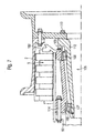
- FIG. 1 shows a wheel bearing 1 according to the invention of an aircraft landing gear.
- the wheel bearing comprises a two-part rim 2 , onto which a tire, not illustrated, is fitted and which is assembled from two rim parts 3 , 4 .
- the rim parts 3 , 4 are joined to each other by connecting screws provided on the circumference and thus form an independent structural unit.
- a brake arrangement 5 can be seen, which is formed from brake linings or brake blocks 7 and brake disks 8 arranged alternatingly along the longitudinal axis 6 .
- the brake arrangement 5 can be pressurized in the axial direction via a ram 10 , shown by way of illustration, by a corresponding axial braking force 12 being exerted on the arrangement.
- a counter-bearing 14 is provided on the other side of the brake arrangement 5 .
- a stub axle or a hollow axle 20 of the aircraft landing gear bears inner rings 21 , 22 of two anti-friction bearings 23 , 24 arranged axially spaced apart.
- the anti-friction bearings 23 , 24 are configured as tapered roller bearings in the exemplary embodiments. In principle, however, other bearings, for example angular contact ball bearings, can also be used.
- the bearing outer rings 25 , 26 of the anti-friction bearings 23 , 24 are jointly accommodated in a one-piece outer ring bearing housing 28 .
- the outer bearing rings 25 , 26 can be pressed into the housing 28 .
- the inner ring 22 of the anti-friction bearing 24 is fixed on the axle 20 in a manner known per se with an axle nut.
- the outer ring bearing housing 28 forms the part 30 which can be rotated—seen in relation to the stationary axle 20 —of the bearing arrangement 31 .
- the rim 2 is detachably joined to a flange-like peripheral extension 32 extending radially outward and belonging to the bearing housing 28 , by means of a plurality of screws 33 arranged on a pitch circle.
- the rim 2 can be removed axially to the right from the wheel bearing or the axle 20 in one piece as a structural unit by loosening the screws 33 .
- the brake arrangement 5 is therefore easily accessible.
- the outer ring bearing housing forms a structural unit which is simple to handle during the mounting and which, in order to fulfill the actual rotational mounting, comprises only a comparatively few individual parts to be mounted.
- FIG. 2 shows a variant of a wheel bearing according to the invention.
- the outer ring bearing housing 40 shown in FIG. 2 is modified in as much as it extends radially further outward than the bearing housing 28 in FIG. 1 .
- the two-part rim 2 with its rim parts 3 and 4 is detachably joined to the outer ring bearing housing 40 .
- the rim parts 3 and 4 are pre-joined by screw connections 44 that are merely indicated, forming a structural unit.
- the outer ring bearing housing forms the rotating part 45 of the bearing arrangement 46 .
- a counter-bearing 50 is provided in a stationary base area 49 , joined by a screw fixing 48 , in order to absorb the axial force exerted by the brake arrangement 5 during operational braking.
- the bearing arrangement 46 has a modification with regard to the bearing inner rings 21 , 22 , in as much as the latter are each provided with an axial extension 53 , 54 .
- the extensions 53 , 54 facing each other axially, form spacers for setting an axial distance between the anti-friction bearings 23 , 24 .
- the extensions 53 , 54 are pre-joined to each other via a clip 56 , as the detail view A illustrated enlarged in FIG. 3 indicates.
- the clip holds the two extensions in position and clamps a peripheral seal 58 between them. Therefore, in an advantageous way, the bearing arrangement 46 is formed as a closed unit protected against contamination and against the penetration of media from outside.
- the bearing inner rings 21 , 22 and the running surfaces formed by the latter for the anti-friction elements—can advantageously be formed integrally from the material 60 of the outer ring bearing housing
- FIG. 4 shows a modified wheel bearing according to the invention which, in the axial direction, is constructed more compactly and is particularly capable of bearing a load and absorbing torques as a result of the fact that the outer anti-friction bearing 70 of the bearing arrangement 71 has a greater diameter than the inner anti-friction bearing 72 .
- the outer ring bearing housing 74 is formed with a step, so to speak, the bearing part of the inner rings of the anti-friction bearings having a corresponding stepped portion 75 .
- the inner part is fixed on the hollow axle 78 of the wheel bearing via an axle nut 77 .
- the bearing arrangement 80 is arranged laterally beside the brake arrangement 5 in the axial direction.
- the rim 2 with its two rim parts 3 , 4 is joined to the outer ring bearing housing 82 via a plurality of axial screws 81 arranged on the pitch circle.
- the bearing inner rings 84 , 85 are fixed on an axle 87 in a manner known per se by an axle nut 86 .
- the screw connection 81 is released and the rim 2 can then be removed axially to the right. It therefore not only exposes the brake arrangement 5 but also, in this exemplary embodiment, a counter-bearing 89 detachably fixed to a support 88 .
- the counter-bearing as already previously described, is used to absorb the braking forces applied by a brake ram 90 and transmitted via the brake linings/brake blocks 7 and brake disks 8 .
- This configuration is particularly advantageous for the brake inspection and maintenance, since the counter-bearing 89 detachably fixed via a screw connection 92 can be removed simply by loosening the connection 92 , and, therefore, the brake disks and brake linings are accessible axially and can be removed from the brake arrangement 5 .
- these can have axial recesses or grooves distributed over the periphery, in which corresponding webs on the rims and the rotating elements, on the one hand, and corresponding webs or projections of a brake caliper or of the support 88 , on the other hand, engage.
- FIGS. 6 to 9 show wheel bearings according to the invention in which the outer ring bearing housing 100 is in each case fixed to a hollow axle 101 or a stub axle rotatably fixed.
- a counter-bearing 102 is detachably fixed to the outer ring bearing housing 100 via a screw connection 103 in the manner and with the advantages as previously already described ( FIGS. 6 and 7 ).
- the counter-bearing 102 can also be fixed to the hollow axle 101 .
- the bearing arrangement 105 is, so to speak, arranged completely inside the brake arrangement 5 . Therefore, despite a comparatively wider spacing of the anti-friction bearings 107 , 108 , a design of the wheel bearing that is very compact in the axial direction can be implemented.
- FIG. 7 for example, in the event of loosening the screw connection 110 , indicated only schematically, between the rim 2 and an inner hollow axle 112 , which is mounted via the anti-friction bearings 107 and 108 such that it can rotate with respect to the outer ring bearing housing 100 , particularly good access to the brake arrangement 5 is possible.
- the embodiment shown in FIG. 7 also has the additional advantage that, following the dismounting of the rim 2 and of the counter-bearing 102 and removal of the brake arrangement 5 , a connecting screw 114 , via which the outer ring bearing housing 100 is screwed to the hollow axle 101 , also becomes accessible from the right-hand side.
- FIG. 8 shows a further form of configuration in which, in the outer ring bearing housing 100 , running surfaces 116 , 117 for the anti-friction elements 118 , 119 of the anti-friction bearings 107 , 108 are integrally formed at the same time.
- the outer ring bearing housing 100 is fixed, for example via a screw fixing or a circlip 120 , in the hollow axle 101 serving as a support.
- the brake arrangement 5 can be implemented as what is known as a “floating” brake caliper even without a specific brake caliper base.
- FIG. 9 shows a further special feature with regard to the fixing of the rim in the rotatable region of the bearing arrangement, which, in this example, is formed by the inner hollow axle 121 .
- the rim 2 here is screwed to the hollow axle 121 in a particularly simple way via an axle nut 122 .
Abstract
Description
-
- A Detail view from
FIG. 2 - 1 Wheel bearing
- 2 Rim
- 3, 4 Rim parts
- 5 Brake arrangement
- 6 Longitudinal axis
- 7 Brake linings/brake blocks
- 8 Brake disks
- 10 Ram
- 12 Braking force
- 14 Counter-bearing
- 20 Stub axle/hollow axle
- 21, 22 Inner rings
- 23, 24 Anti-friction bearings
- 25, 26 Bearing outer rings
- 28 Outer ring bearing housing
- 30 Axle nut
- 31 Rotatable part
- 32 Extension
- 33 Screws
- 40 Outer ring bearing housing
- 42 Screw joints
- 44 Screw connections
- 45 Rotating part
- 46 Bearing arrangement
- 48 Screw joint
- 49 Base area
- 50 Counter-bearing
- 53, 54 Extensions
- 56 Clip
- 58 Seal
- 60 Material of the outer ring bearing housing
- 70 Outer anti-friction bearing
- 71 Bearing arrangement
- 72 Inner anti-friction bearing
- 74 Outer ring bearing housing
- 75 Stepped portion
- 77 Axle nut
- 78 Hollow axle
- 80 Bearing arrangement
- 81 Screw joint
- 82 Outer ring bearing housing
- 84, 85 Bearing inner rings
- 86 Axle nut
- 87 Axle
- 88 Support
- 89 Counter-bearing
- 90 Brake ram
- 92 Screw connection
- 100 Outer ring bearing housing
- 101 Hollow axle
- 102 Counter-bearing
- 103 Screw connection
- 105 Bearing arrangement
- 107, 108 Anti-friction bearings
- 110 Screw connection
- 112 Hollow axle
- 114 Connecting screw
- 116, 117 Running surfaces
- 118, 119 Anti-friction elements
- 120 Circlip
- 121 Inner hollow axle
- 122 Axle nut
- A Detail view from
Claims (6)
Applications Claiming Priority (4)
| Application Number | Priority Date | Filing Date | Title |
|---|---|---|---|
| DE102007042369 | 2007-09-06 | ||
| DE102007042369.3 | 2007-09-06 | ||
| DE102007042369A DE102007042369A1 (en) | 2007-09-06 | 2007-09-06 | Wheel bearing of an aircraft landing gear |
| PCT/DE2008/001430 WO2009030200A1 (en) | 2007-09-06 | 2008-08-27 | Wheel bearing of an aircraft landing gear |
Publications (2)
| Publication Number | Publication Date |
|---|---|
| US20100202719A1 US20100202719A1 (en) | 2010-08-12 |
| US8992093B2 true US8992093B2 (en) | 2015-03-31 |
Family
ID=39952235
Family Applications (1)
| Application Number | Title | Priority Date | Filing Date |
|---|---|---|---|
| US12/676,149 Expired - Fee Related US8992093B2 (en) | 2007-09-06 | 2008-08-27 | Wheel bearing of an aircraft landing gear |
Country Status (4)
| Country | Link |
|---|---|
| US (1) | US8992093B2 (en) |
| EP (1) | EP2195176B1 (en) |
| DE (1) | DE102007042369A1 (en) |
| WO (1) | WO2009030200A1 (en) |
Cited By (1)
| Publication number | Priority date | Publication date | Assignee | Title |
|---|---|---|---|---|
| CN111559199A (en) * | 2020-05-22 | 2020-08-21 | 福建申利卡铝业发展有限公司 | Novel vehicle hub with good brake performance |
Families Citing this family (4)
| Publication number | Priority date | Publication date | Assignee | Title |
|---|---|---|---|---|
| DE102007059587A1 (en) * | 2007-12-11 | 2009-06-18 | Schaeffler Kg | Wheel bearing of an aircraft landing gear |
| DE102010047932A1 (en) | 2010-10-08 | 2012-04-12 | Schaeffler Technologies Gmbh & Co. Kg | wheel bearing unit |
| DE102016218134A1 (en) * | 2016-09-21 | 2018-03-22 | Schaeffler Technologies AG & Co. KG | Bearing arrangement with adjustable bearing preload |
| GB2587431A (en) * | 2019-09-30 | 2021-03-31 | Airbus Operations Ltd | Bearing unit for an aircraft wheel |
Citations (18)
| Publication number | Priority date | Publication date | Assignee | Title |
|---|---|---|---|---|
| US1950592A (en) * | 1932-03-10 | 1934-03-13 | Yellow Truck & Coach Mfg Co | Outer wheel bearing retention |
| US2048442A (en) * | 1931-07-06 | 1936-07-21 | Bendix Brake Co | Wheel |
| US2406068A (en) | 1944-07-20 | 1946-08-20 | Bendix Aviat Corp | Wheel construction |
| US2834636A (en) * | 1953-10-28 | 1958-05-13 | Thomas L Fawick | Forged wheel |
| US2998282A (en) | 1956-11-23 | 1961-08-29 | Bendix Corp | Forged wheel constructions and process of making same |
| US3836201A (en) * | 1971-07-27 | 1974-09-17 | Dunlop Ltd | Wheel assemblies |
| US5086821A (en) * | 1990-01-23 | 1992-02-11 | The B. F. Goodrich Company | Aircraft wheel |
| US5096310A (en) * | 1985-10-25 | 1992-03-17 | Skf Gmbh | Rolling bearing with separated bearing ring |
| JPH05162502A (en) * | 1991-12-13 | 1993-06-29 | Honda Motor Co Ltd | Wheel hub with brake drum |
| US5402865A (en) * | 1993-07-01 | 1995-04-04 | Alliedsignal Inc. | Aircraft brake assembly retention mechanism |
| US5492419A (en) * | 1994-07-19 | 1996-02-20 | Ntn Corporation | Cartridge axle pinion bearing assembly |
| US5641239A (en) * | 1994-04-21 | 1997-06-24 | Skf Gmbh | Device for connecting bearing rings |
| US6615958B1 (en) | 1999-09-13 | 2003-09-09 | Goodrich Corporation | Integrated aircraft wheel, brake and axle for all-electric aircraft braking system |
| US7255208B2 (en) * | 2004-02-13 | 2007-08-14 | Honeywell International Inc. | Aircraft brake wheel heat shield |
| US7393064B2 (en) * | 2004-03-22 | 2008-07-01 | Webb Wheel Products, Inc. | Wheel hub with improved pilot construction and a method for manufacturing |
| US7537390B2 (en) * | 2004-09-08 | 2009-05-26 | Fag Kugelfischer Ag | Rolling bearing arrangement |
| US8444324B2 (en) * | 2007-12-11 | 2013-05-21 | Schaeffler Technologies AG & Co. KG | Wheel bearing for an aircraft landing gear |
| US8668276B2 (en) * | 2011-07-14 | 2014-03-11 | Meggitt Aircraft Braking Systems | Wheel assembly heat shield |
-
2007
- 2007-09-06 DE DE102007042369A patent/DE102007042369A1/en not_active Withdrawn
-
2008
- 2008-08-27 EP EP08801238A patent/EP2195176B1/en not_active Not-in-force
- 2008-08-27 US US12/676,149 patent/US8992093B2/en not_active Expired - Fee Related
- 2008-08-27 WO PCT/DE2008/001430 patent/WO2009030200A1/en active Application Filing
Patent Citations (18)
| Publication number | Priority date | Publication date | Assignee | Title |
|---|---|---|---|---|
| US2048442A (en) * | 1931-07-06 | 1936-07-21 | Bendix Brake Co | Wheel |
| US1950592A (en) * | 1932-03-10 | 1934-03-13 | Yellow Truck & Coach Mfg Co | Outer wheel bearing retention |
| US2406068A (en) | 1944-07-20 | 1946-08-20 | Bendix Aviat Corp | Wheel construction |
| US2834636A (en) * | 1953-10-28 | 1958-05-13 | Thomas L Fawick | Forged wheel |
| US2998282A (en) | 1956-11-23 | 1961-08-29 | Bendix Corp | Forged wheel constructions and process of making same |
| US3836201A (en) * | 1971-07-27 | 1974-09-17 | Dunlop Ltd | Wheel assemblies |
| US5096310A (en) * | 1985-10-25 | 1992-03-17 | Skf Gmbh | Rolling bearing with separated bearing ring |
| US5086821A (en) * | 1990-01-23 | 1992-02-11 | The B. F. Goodrich Company | Aircraft wheel |
| JPH05162502A (en) * | 1991-12-13 | 1993-06-29 | Honda Motor Co Ltd | Wheel hub with brake drum |
| US5402865A (en) * | 1993-07-01 | 1995-04-04 | Alliedsignal Inc. | Aircraft brake assembly retention mechanism |
| US5641239A (en) * | 1994-04-21 | 1997-06-24 | Skf Gmbh | Device for connecting bearing rings |
| US5492419A (en) * | 1994-07-19 | 1996-02-20 | Ntn Corporation | Cartridge axle pinion bearing assembly |
| US6615958B1 (en) | 1999-09-13 | 2003-09-09 | Goodrich Corporation | Integrated aircraft wheel, brake and axle for all-electric aircraft braking system |
| US7255208B2 (en) * | 2004-02-13 | 2007-08-14 | Honeywell International Inc. | Aircraft brake wheel heat shield |
| US7393064B2 (en) * | 2004-03-22 | 2008-07-01 | Webb Wheel Products, Inc. | Wheel hub with improved pilot construction and a method for manufacturing |
| US7537390B2 (en) * | 2004-09-08 | 2009-05-26 | Fag Kugelfischer Ag | Rolling bearing arrangement |
| US8444324B2 (en) * | 2007-12-11 | 2013-05-21 | Schaeffler Technologies AG & Co. KG | Wheel bearing for an aircraft landing gear |
| US8668276B2 (en) * | 2011-07-14 | 2014-03-11 | Meggitt Aircraft Braking Systems | Wheel assembly heat shield |
Non-Patent Citations (1)
| Title |
|---|
| Machine translation of JP 05162502 A obtained on Mar. 14, 2014. * |
Cited By (1)
| Publication number | Priority date | Publication date | Assignee | Title |
|---|---|---|---|---|
| CN111559199A (en) * | 2020-05-22 | 2020-08-21 | 福建申利卡铝业发展有限公司 | Novel vehicle hub with good brake performance |
Also Published As
| Publication number | Publication date |
|---|---|
| US20100202719A1 (en) | 2010-08-12 |
| DE102007042369A1 (en) | 2009-03-12 |
| EP2195176B1 (en) | 2013-03-27 |
| WO2009030200A1 (en) | 2009-03-12 |
| EP2195176A1 (en) | 2010-06-16 |
Similar Documents
| Publication | Publication Date | Title |
|---|---|---|
| US8992093B2 (en) | Wheel bearing of an aircraft landing gear | |
| US9429201B2 (en) | Braking device with a brake caliper attachment | |
| US10704627B2 (en) | Multi-piece rotor for use with an electric wheel end drive motor | |
| KR101728024B1 (en) | Wheel hub, brake disk, and wheel bearing assembly provided with the same | |
| US20100258387A1 (en) | Annular disk brake and method of increasing a brake pad clamping force | |
| JP2005502005A5 (en) | ||
| KR20170004769A (en) | Wheel hub | |
| JP2005517580A (en) | Wheel hub assembly | |
| JP2012072904A (en) | Adapter discrete type disk rotor | |
| US20060249338A1 (en) | Compact integrated brake system | |
| CN108791483B (en) | Wheel end assembly with deflector | |
| CN113015565A (en) | Brake system, axle bearing unit for a vehicle, vehicle having such an axle bearing unit and drive unit | |
| US6872163B2 (en) | Planetary wheelend | |
| US10072717B2 (en) | Driven wheel assembly and automotive vehicle equipped with such an assembly | |
| JP2007085393A (en) | Rolling bearing unit for supporting wheel | |
| KR101532078B1 (en) | Separatable brake disk, wheel bearing assembly provided with the same and method of restricting runout of brake disk | |
| JP5304113B2 (en) | Axle bearing fastening structure | |
| JP2008007053A (en) | Rolling bearing device for wheel | |
| CN108791484B (en) | Wheel end assembly with compression ring and method of assembly | |
| JP2008223982A (en) | Wheel rotation supporting device with disc brake | |
| KR101885141B1 (en) | Wheel bearing assembly | |
| KR20200120562A (en) | Wheel bearing assembly | |
| JP2007069746A (en) | Bearing unit | |
| JP2020131821A (en) | Wheel hub device | |
| WO2021060442A1 (en) | Water infiltration prevention structure for vehicle disc brake |
Legal Events
| Date | Code | Title | Description |
|---|---|---|---|
| AS | Assignment |
Owner name: SCHAEFFLER TECHNOLOGIES GMBH & CO. KG, GERMANY Free format text: ASSIGNMENT OF ASSIGNORS INTEREST;ASSIGNORS:DOTZEL, TORSTEN;LANG, ROBIN;PROESCHEL, CHRISTIAN;AND OTHERS;REEL/FRAME:024166/0744 Effective date: 20100212 |
|
| AS | Assignment |
Owner name: SCHAEFFLER TECHNOLOGIES AG & CO. KG, GERMANY Free format text: CHANGE OF NAME;ASSIGNOR:SCHAEFFLER TECHNOLOGIES GMBH & CO. KG;REEL/FRAME:028533/0036 Effective date: 20120119 |
|
| STCF | Information on status: patent grant |
Free format text: PATENTED CASE |
|
| AS | Assignment |
Owner name: SCHAEFFLER TECHNOLOGIES AG & CO. KG, GERMANY Free format text: CHANGE OF NAME;ASSIGNOR:SCHAEFFLER TECHNOLOGIES GMBH & CO. KG;REEL/FRAME:037732/0347 Effective date: 20150101 Owner name: SCHAEFFLER TECHNOLOGIES GMBH & CO. KG, GERMANY Free format text: MERGER AND CHANGE OF NAME;ASSIGNORS:SCHAEFFLER TECHNOLOGIES AG & CO. KG;SCHAEFFLER VERWALTUNGS 5 GMBH;REEL/FRAME:037732/0228 Effective date: 20131231 |
|
| AS | Assignment |
Owner name: SCHAEFFLER TECHNOLOGIES AG & CO. KG, GERMANY Free format text: CORRECTIVE ASSIGNMENT TO CORRECT THE PROPERTY NUMBERS PREVIOUSLY RECORDED ON REEL 037732 FRAME 0347. ASSIGNOR(S) HEREBY CONFIRMS THE APP. NO. 14/553248 SHOULD BE APP. NO. 14/553258;ASSIGNOR:SCHAEFFLER TECHNOLOGIES GMBH & CO. KG;REEL/FRAME:040404/0530 Effective date: 20150101 |
|
| FEPP | Fee payment procedure |
Free format text: MAINTENANCE FEE REMINDER MAILED (ORIGINAL EVENT CODE: REM.); ENTITY STATUS OF PATENT OWNER: LARGE ENTITY |
|
| LAPS | Lapse for failure to pay maintenance fees |
Free format text: PATENT EXPIRED FOR FAILURE TO PAY MAINTENANCE FEES (ORIGINAL EVENT CODE: EXP.); ENTITY STATUS OF PATENT OWNER: LARGE ENTITY |
|
| STCH | Information on status: patent discontinuation |
Free format text: PATENT EXPIRED DUE TO NONPAYMENT OF MAINTENANCE FEES UNDER 37 CFR 1.362 |
|
| FP | Lapsed due to failure to pay maintenance fee |
Effective date: 20190331 |