US8991876B2 - Connection means and method for connecting at least two fluid-conducting medical-technical systems, as well as medical-technical apparatus - Google Patents
Connection means and method for connecting at least two fluid-conducting medical-technical systems, as well as medical-technical apparatus Download PDFInfo
- Publication number
- US8991876B2 US8991876B2 US12/765,933 US76593310A US8991876B2 US 8991876 B2 US8991876 B2 US 8991876B2 US 76593310 A US76593310 A US 76593310A US 8991876 B2 US8991876 B2 US 8991876B2
- Authority
- US
- United States
- Prior art keywords
- pipe
- connection
- pipe section
- widening
- connection means
- Prior art date
- Legal status (The legal status is an assumption and is not a legal conclusion. Google has not performed a legal analysis and makes no representation as to the accuracy of the status listed.)
- Active, expires
Links
Images




Classifications
-
- F—MECHANICAL ENGINEERING; LIGHTING; HEATING; WEAPONS; BLASTING
- F16—ENGINEERING ELEMENTS AND UNITS; GENERAL MEASURES FOR PRODUCING AND MAINTAINING EFFECTIVE FUNCTIONING OF MACHINES OR INSTALLATIONS; THERMAL INSULATION IN GENERAL
- F16L—PIPES; JOINTS OR FITTINGS FOR PIPES; SUPPORTS FOR PIPES, CABLES OR PROTECTIVE TUBING; MEANS FOR THERMAL INSULATION IN GENERAL
- F16L25/00—Construction or details of pipe joints not provided for in, or of interest apart from, groups F16L13/00 - F16L23/00
- F16L25/10—Sleeveless joints between two pipes, one being introduced into the other
-
- A—HUMAN NECESSITIES
- A61—MEDICAL OR VETERINARY SCIENCE; HYGIENE
- A61M—DEVICES FOR INTRODUCING MEDIA INTO, OR ONTO, THE BODY; DEVICES FOR TRANSDUCING BODY MEDIA OR FOR TAKING MEDIA FROM THE BODY; DEVICES FOR PRODUCING OR ENDING SLEEP OR STUPOR
- A61M39/00—Tubes, tube connectors, tube couplings, valves, access sites or the like, specially adapted for medical use
- A61M39/10—Tube connectors or tube couplings
-
- A—HUMAN NECESSITIES
- A61—MEDICAL OR VETERINARY SCIENCE; HYGIENE
- A61M—DEVICES FOR INTRODUCING MEDIA INTO, OR ONTO, THE BODY; DEVICES FOR TRANSDUCING BODY MEDIA OR FOR TAKING MEDIA FROM THE BODY; DEVICES FOR PRODUCING OR ENDING SLEEP OR STUPOR
- A61M1/00—Suction or pumping devices for medical purposes; Devices for carrying-off, for treatment of, or for carrying-over, body-liquids; Drainage systems
- A61M1/36—Other treatment of blood in a by-pass of the natural circulatory system, e.g. temperature adaptation, irradiation ; Extra-corporeal blood circuits
- A61M1/3621—Extra-corporeal blood circuits
- A61M1/3622—Extra-corporeal blood circuits with a cassette forming partially or totally the blood circuit
-
- A—HUMAN NECESSITIES
- A61—MEDICAL OR VETERINARY SCIENCE; HYGIENE
- A61M—DEVICES FOR INTRODUCING MEDIA INTO, OR ONTO, THE BODY; DEVICES FOR TRANSDUCING BODY MEDIA OR FOR TAKING MEDIA FROM THE BODY; DEVICES FOR PRODUCING OR ENDING SLEEP OR STUPOR
- A61M39/00—Tubes, tube connectors, tube couplings, valves, access sites or the like, specially adapted for medical use
- A61M39/10—Tube connectors or tube couplings
- A61M39/105—Multi-channel connectors or couplings, e.g. for connecting multi-lumen tubes
-
- A—HUMAN NECESSITIES
- A61—MEDICAL OR VETERINARY SCIENCE; HYGIENE
- A61M—DEVICES FOR INTRODUCING MEDIA INTO, OR ONTO, THE BODY; DEVICES FOR TRANSDUCING BODY MEDIA OR FOR TAKING MEDIA FROM THE BODY; DEVICES FOR PRODUCING OR ENDING SLEEP OR STUPOR
- A61M39/00—Tubes, tube connectors, tube couplings, valves, access sites or the like, specially adapted for medical use
- A61M39/10—Tube connectors or tube couplings
- A61M39/16—Tube connectors or tube couplings having provision for disinfection or sterilisation
- A61M39/18—Methods or apparatus for making the connection under sterile conditions, i.e. sterile docking
-
- A—HUMAN NECESSITIES
- A61—MEDICAL OR VETERINARY SCIENCE; HYGIENE
- A61M—DEVICES FOR INTRODUCING MEDIA INTO, OR ONTO, THE BODY; DEVICES FOR TRANSDUCING BODY MEDIA OR FOR TAKING MEDIA FROM THE BODY; DEVICES FOR PRODUCING OR ENDING SLEEP OR STUPOR
- A61M1/00—Suction or pumping devices for medical purposes; Devices for carrying-off, for treatment of, or for carrying-over, body-liquids; Drainage systems
- A61M1/14—Dialysis systems; Artificial kidneys; Blood oxygenators ; Reciprocating systems for treatment of body fluids, e.g. single needle systems for hemofiltration or pheresis
-
- A—HUMAN NECESSITIES
- A61—MEDICAL OR VETERINARY SCIENCE; HYGIENE
- A61M—DEVICES FOR INTRODUCING MEDIA INTO, OR ONTO, THE BODY; DEVICES FOR TRANSDUCING BODY MEDIA OR FOR TAKING MEDIA FROM THE BODY; DEVICES FOR PRODUCING OR ENDING SLEEP OR STUPOR
- A61M1/00—Suction or pumping devices for medical purposes; Devices for carrying-off, for treatment of, or for carrying-over, body-liquids; Drainage systems
- A61M1/36—Other treatment of blood in a by-pass of the natural circulatory system, e.g. temperature adaptation, irradiation ; Extra-corporeal blood circuits
- A61M1/3621—Extra-corporeal blood circuits
- A61M1/3622—Extra-corporeal blood circuits with a cassette forming partially or totally the blood circuit
- A61M1/36226—Constructional details of cassettes, e.g. specific details on material or shape
-
- A—HUMAN NECESSITIES
- A61—MEDICAL OR VETERINARY SCIENCE; HYGIENE
- A61M—DEVICES FOR INTRODUCING MEDIA INTO, OR ONTO, THE BODY; DEVICES FOR TRANSDUCING BODY MEDIA OR FOR TAKING MEDIA FROM THE BODY; DEVICES FOR PRODUCING OR ENDING SLEEP OR STUPOR
- A61M39/00—Tubes, tube connectors, tube couplings, valves, access sites or the like, specially adapted for medical use
- A61M39/10—Tube connectors or tube couplings
- A61M2039/1027—Quick-acting type connectors
-
- A—HUMAN NECESSITIES
- A61—MEDICAL OR VETERINARY SCIENCE; HYGIENE
- A61M—DEVICES FOR INTRODUCING MEDIA INTO, OR ONTO, THE BODY; DEVICES FOR TRANSDUCING BODY MEDIA OR FOR TAKING MEDIA FROM THE BODY; DEVICES FOR PRODUCING OR ENDING SLEEP OR STUPOR
- A61M39/00—Tubes, tube connectors, tube couplings, valves, access sites or the like, specially adapted for medical use
- A61M39/10—Tube connectors or tube couplings
- A61M2039/1072—Tube connectors or tube couplings with a septum present in the connector
-
- Y—GENERAL TAGGING OF NEW TECHNOLOGICAL DEVELOPMENTS; GENERAL TAGGING OF CROSS-SECTIONAL TECHNOLOGIES SPANNING OVER SEVERAL SECTIONS OF THE IPC; TECHNICAL SUBJECTS COVERED BY FORMER USPC CROSS-REFERENCE ART COLLECTIONS [XRACs] AND DIGESTS
- Y10—TECHNICAL SUBJECTS COVERED BY FORMER USPC
- Y10S—TECHNICAL SUBJECTS COVERED BY FORMER USPC CROSS-REFERENCE ART COLLECTIONS [XRACs] AND DIGESTS
- Y10S604/00—Surgery
- Y10S604/905—Aseptic connectors or couplings, e.g. frangible, piercable
Definitions
- the present invention relates to a connection means. It further relates to a method for connecting at least two fluid-conducting medical-technical systems, as well as an external medical-technical functional means and a medical-technical apparatus. Furthermore it relates to a drip-protection means and a closure sleeve.
- External functional means are regularly employed with treatment and analytic apparatuses in medical or laboratory technology.
- Such external functional means which may be based on tube systems and cassette arrangements, are frequently connected to the treatment and analytic apparatus and/or to another external functional means by establishing a fluid connection for liquids and/or gases.
- connection means of the invention serves for the fluid connection of at least one first fluid-conducting system and a second fluid-conducting system (further below also referred to as a connection system) and comprises at least one first pipe section of the first system which is intended to be connected to a second pipe section of the second system.
- a fluid connection between two systems may advantageously be established.
- the respective systems may each be an external functional means and/or a treatment apparatus between which a fluid connection is to be established.
- pipe or “pipe section” as presently used designates a pipe passage or a pipe conduit suited and intended for receiving and/or passing on fluids.
- the first or the second pipe or pipe section comprises at least one inner pipe and at least one outer pipe.
- the inner pipe is arranged in an interior of the outer pipe.
- the inner pipe and the outer pipe may have a concentric or non-concentric arrangement relative to each other.
- the inner pipe and the outer pipe may be arranged on an external functional means or on a treatment apparatus, or may be provided for being arranged there.
- connection means may be suited for receiving at least one portion of the connection pipe of a treatment apparatus or of an external functional means between the inner pipe and the outer pipe.
- connection pipe designates a pipe, a pipe section, a passage, a conduit or the like, which is adapted to be connected or is connected to the connection means of the invention.
- connection pipe may be flexible or rigid.
- connection pipe may be received by a portion thereof in an interstice between the inner pipe and the outer pipe of the connection means.
- a fluid connection may be provided between an interior of the inner pipe and an interior of the outer pipe.
- the first and/or the second system may be a respective external medical-technical functional means, medical-technical treatment or blood treatment apparatus, medical analytic apparatus, or the like systems conducting medical fluids (in particular liquids and gases).
- connection means may comprise a closure means for short-circuiting the inner lumen and the annular gap between the inner pipe and the outer pipe for the purpose of rinsing and/or disinfecting all of the inner surfaces of the system getting into contact with fluid.
- connection means may comprise a widening for connecting—in particular by jamming or expanding—the inner pipe against the connection pipe.
- the widening may be present on the inner pipe or on the connection pipe. It may be present as a result of integral manufacture with the inner pipe or the connection pipe, or may have been connected to the latter. It may have a spherical or convex outer surface. It may be intended to effect a fluidic seal between inner pipe and connection pipe in the ready-to-use, connected condition of the connection means.
- the widening may have a spherical and/or globular and/or curved and/or arc-shaped and/or convex outer surface, in particular in a region of the maximum cross-section or diameter, preferably in a direction of flow.
- the widening may be configured so as to effect a fluidic seal between the first pipe section and the second pipe section, in particular between inner pipe and connection pipe, in the ready-to-use, connected condition of the connection means.
- the widening may have its largest cross-sectional diameter or its largest circumference in a cross-section in a plane perpendicular to the direction of connection of the first pipe section to the second pipe section, in a region of the widening that is central in the direction of connection.
- the direction of connection may be an axial direction of the pipe section to which the widening is connected.
- the widening may have its largest cross-sectional diameter or its largest circumference in a cross-section in a plane perpendicular to a direction of extension of the inner lumen of the one pipe section to which the widening is connected, in a region of the widening that is central in the direction of connection.
- the widening may have the same diameter and/or circumference in at least three different sectional planes through a central point of the widening or in at least three different sectional planes containing a common straight line.
- the diameter or the cross-sectional diameter of the widening may be circular.
- the widening may be configured such that it may be moved, in the process of connecting the first pipe section to the second pipe section, along a displacement path in the pipe section into which it is being introduced, while maintaining the sealing condition brought about by it, and/or may be configured such that it may be tilted, in the process of connecting the first pipe section to the second pipe section or following completion of connecting, by an angle relative to the direction of flow, while maintaining the sealing condition brought about by it.
- the connected pipe sections may therefore be telescoped some further distance in an inward or outward direction without having to relinquish the connected condition obtained by means of the widening.
- the connected pipe sections may be tilted slightly relative to each other or be folded jointly in their connection to each other without relinquishing the connected condition or causing a leakage.
- the widening may be configured such that it may be moved, in the process of connecting the first pipe section to the second pipe section, along a displacement path in the pipe section into which it is being introduced, while maintaining the sealing condition brought about by it.
- the displacement path may be 1, 2, 3, 4, 5, 6, 7, 8, 9, 10 or more millimeters (mm).
- the widening may be configured such that it may be tilted, in the process of connecting the first pipe section to the second pipe section or following completion of connecting, by an angle relative to the direction of flow while maintaining the sealing condition brought about by it.
- the angle may be in a range from 1 to 3 degrees; it may be in a range from 1 to 5 degrees, 1 to 8 degrees, or 1 to 10 degrees. It may adopt numeric values of 1, 2, 3, 4, 5, 6, 7, 8, 9, or 10 degrees or more.
- connection means of the invention may comprise another, second sealing means.
- this second sealing means may be arranged adjacent to the widening.
- connection means may comprise a pressure limiting valve. It may comprise a waste water branch.
- connection means may comprise a pivotal mount for lateral and/or horizontal alignment of the inner pipe and/or of the outer pipe and/or of the connection pipe relative to each other.
- connection means may comprise a pre-centering means for—vertical and/or lateral—alignment of the inner pipe and/or of the outer pipe and/or of the connection pipe prior to establishing the fluid connection.
- the pre-centering means may comprise at least two springily deflectable tongues.
- connection means may comprise a touch-prevention panel for preventing an interior from being contaminated and/or the connection pipe from being touched by a user.
- the touch-prevention panel may be retained in the external, medical-technical functional means by a latching arrangement. It may comprise a plurality of bendable segments. A number of bendable segments may be bendable independently of other segments.
- connection means may comprise a means which is mechanically altered and/or moved in the process of connecting such that the effected connection continues to be apparent on the means following disconnection.
- This means may be the touch-prevention panel.
- connection means may comprise a bellows arrangement. This may be part of the outer pipe.
- the outer pipe may comprise at least one spring member for tightening the bellows arrangement.
- connection means may comprise a means for moving the closure means, for example a removable rinsing cap, for exposing an opening of the inner pipe in order to establish the fluid connection.
- the rinsing cap may be adapted to be moved automatically for exposing with the aid of the means.
- the inner pipe and the outer pipe may be arranged for axial displacement relative to each other.
- the connection means may comprise a means—in particular an automatic means—for axially displacing the inner pipe and/or the outer pipe relative to each other.
- connection means may comprise a means for axially displacing both the inner pipe and the outer pipe.
- the relative position of inner pipe and outer pipe may remain unchanged or may change.
- Materials participating in the realization of the range of flow of the fluid connection to be obtained may be hydrophilic.
- surfaces in the range of flow may have a hydrophilic coating.
- connection means of the invention may be employed, for example, as an automatic substituate connector.
- Coupling may take place through the intermediary of a sliding guide or by making use of the fact that the rinsing cap will be pivoted whenever the connection means is in the pivoting position.
- connection means of the invention and/or the medical-technical apparatus of the invention may comprise sensors for detecting positions or attitudes of single elements of the connection means (for example of inner pipe, outer pipe, rinsing cap, connection pipe, etc.).
- the sensor apparatuses used may equally be based on various principles (axial detection of position, e.g., with the aid of photoelectric barriers or detection of the spindle's rotation, detection of the pivoting movement also with the aid of photoelectric barriers, switches, rotary potentiometers, and the like).
- the liquid flowing through the connection means of the invention in the connected condition of a disposable may first of all be utilized for filling and rinsing the external functional means, and later on during the treatment as a substituate.
- a fully automatic connection e.g., of a dialyzer (or of a rinse port) is equally encompassed by the invention.
- An “external functional means” may be a single-use component or a single-use article. It may be made of a plastic material.
- the external functional means of the invention may be intended for use in a treatment method.
- Treatment methods within the meaning of the present invention include medical or medical-technical treatment methods as well as analytic methods in laboratory technology.
- the external functional means of the invention is configured as a blood cassette.
- a blood cassette within the meaning of the present invention is, for example, described in the German Patent Application No. 10 2009 018 664.6 (representative's file FM19A27) and German Patent Application No. 10 2009 024 468.9. (09/33-d01 DE; FM19B27) filed by the applicant of the present invention with the German Patent and Trademark Office on Apr. 23, 2009 and Jun. 10, 2009, respectively, and each having the title “Externeforensics responded, Blut intensitysvortechnischtechnischtechnischtechnischtechnisch
- Example 1 Example, blood treatment apparatus for receiving an external functional means in accordance with the invention, and method]
- connection means of the invention may also be obtained in an undiminished manner with the method of the invention.
- connection means of the invention is used.
- an expansion of the inner lumen of the connection pipe by means of the widening of the inner pipe may take place, to thereby obtain a fluid-tight connection.
- the method may further include performing an automatic routine for determining possibly existing leakages of the fluid connection obtained with the aid of the connection means and/or the operation of a pressure limiting valve of the connection means.
- the rinsing cap may be pivoted automatically for exposing the inner pipe in order to establish the fluid connection.
- the object of the invention is also achieved through a treatment apparatus of the invention. All the advantages of the connection means of the invention may in turn be achieved in an undiminished manner with the treatment apparatus of the invention.
- the treatment apparatus is a blood treatment apparatus such as a dialyzing apparatus, for performing a dialysis treatment such as a hemodialysis, hemofiltration, hemodiafiltration, and the like.
- the treatment apparatus may equally be suited for performing a peritoneal dialysis.
- the object of the invention is also achieved through a drip-protection means and a closure sleeve.
- connection means of the invention may advantageously serve for automatically establishing a connection between two fluid-conducting systems, in particular for a liquid. This may provide the advantage that during the connection, the user will in principle not get into contact with parts that get into contact with fluid or liquid. In this way, a contamination of the location of connection and/or of the conveyed fluid may advantageously be reduced or precluded during the connection.
- the user may advantageously be relieved; the user needs not to undergo training. Furthermore the risk of an error or even damage-causing connection is eliminated.
- the connecting operation may be integrated into an automated overall operation that may be carried out without intervention by the user (e.g.: initial testing of the machine with subsequent filling/rinsing).
- connection means of the invention it is advantageously possible to ensure a substantially complete access involving low pressure losses to any surfaces of the external functional means to be sterilized, which is generally required for sterilization methods utilizing gas.
- Closing the connection means in an automatic and/or automated manner may moreover advantageously avoid trickling out of residual liquid quantities from the connection openings after termination of a treatment procedure.
- connection means of the invention and/or the external functional means of the invention may advantageously be equipped with a reuse prevention means.
- a reuse prevention means advantageously indicating in an easily recognizable form that the external functional means was already used.
- connection means of the invention may advantageously enable to ensure maximum possible filling and/or draining processes through rheologically appropriate configuration and arrangement of any fluid-conducting regions (also in short: fluid regions), in particular of the inner pipe, of the outer pipe and of the connection pipe. In this way, it may advantageously also be ensured that a minimum possible residual quantity of liquid remains in the fluid system of the treatment apparatus used, with no liquid at all or only very little liquid leaking out into the environment of the connection opening.
- the inner lumen of the inner pipe may be partly emptied or may have no liquid content at all at the time of removing the rinsing cap, it is thus advantageously possible to reduce or even avoid the risk of projected droplets of liquid—which might at the last moment, during removal of the rinsing cap, still have contact with non-sterile zones of the outer pipe and/or of the rinsing cap—mixing with sterile residual liquids in the connection means and thus possibly being transferred into the inner lumen of the inner pipe upon repeated connection to the connection partner.
- connection means of the invention may also advantageously ensure freedom from dead spaces and/or stationary eddies. This may be of particular advantage during sterilization.
- connection means of the invention In the case of a horizontal connection assembly the inner lumen and the outer lumen generally remain filled with rinsing solution following rinsing. This implies the risk of at least small quantities of liquid getting into the environment every time the closure cap or rinsing cap is removed manually. This may advantageously be avoided with the connection means of the invention.
- closure cap or rinsing cap of the connection means of the invention may advantageously result in the avoidance of secondary spaces. This allows simplified and particularly thorough disinfection and rinsing.
- the rinsing cap is preferably adapted in a rheologically favorable manner on the inside, so that all of the flow regions may advantageously be rinsed to a sufficient extent or degree during disinfection and rinsing.
- a corresponding—e.g. conical—configuration of the inner pipe furthermore advantageously allows to ensure that critical sealing regions are subjected to particularly intense disinfection and rinsing.
- the rotational flow achievable due to the configuration it is possible to reach even narrow joints while at the same time creating the rheological preconditions for a return flow of the fluids via the outer lumen.
- connection means of the invention may advantageously provide a realization of all relevant areas that provides maximum possible safety against touch and—where possible—even coughing.
- connection means of the invention may furthermore advantageously be configured to be particularly intolerant of tolerances. This is advantageously true both for tolerances within the single partial arrangements of treatment apparatus and external functional means and for the tolerance compatibility of the two connection partners or fluid systems among each other. Both in manual and automated execution of the actual connecting operation, it is thus advantageously possible to provide a maximum possible—in particular lateral—tolerance of the connection partners before and during the connection and to also admit a maximum possible tolerance for the sliding movements in the direction of connecting. As a combination of both tolerances, a sufficient angular tolerance among the axes of connection of the two connection partners may advantageously be provided.
- connection means of the invention advantageously provides sufficient tightness until termination of the treatment.
- the connection means of the invention is advantageously capable of counteracting the case of a leakage occurring nevertheless.
- it is advantageously possible to detect leaked liquid and discharge it in a controlled manner.
- connection means of the invention advantageously provides a design of the arrangement involving low transversal forces, in particular with concurrent action of gravity and by making use of the maximum lateral tolerance.
- connection means of the invention By means of the connection means of the invention, the treatment apparatus is advantageously protected against undesired access to the connection regions, so that maintenance and/or inspection of these regions may advantageously be reduced. In this way, it may advantageously be possible to reduce the costs required for maintenance of the treatment apparatus.
- connection arrangement may advantageously be inspected and/or exchanged easily.
- connection means of the invention it is furthermore possible to avoid elastomer seals in the range or area of the treatment apparatus. In this way, it is advantageously possible to avoid boundary zones and/or dead space zones between the elastomer seals and their installation spaces that are otherwise poorly suited for rinsing through.
- connection means of the invention when the connection means of the invention is provided on the side of an external functional means, the outer pipe is advantageously protected against touch following removal of the rinsing cap or protective cap, and so is the outer pipe of the connection means on the side of the treatment apparatus. In this way it is equally advantageously possible to avoid transfer or introduction of germs into the inner pipe during the connection to the treatment apparatus.
- a first embodiment represents an automatically connecting arrangement between an external functional means and a treatment apparatus.
- connection means of the invention is customarily configured and provided as a part of the treatment apparatus.
- Such an arrangement may be usable in a particularly advantageous manner in connections between external functional means and treatment apparatuses where several three-dimensionally defined connections between external functional means and treatment apparatus should or have to be achieved simultaneously.
- Such an arrangement may, for example, be provided for an automatic substituate connection of an external functional means such as, for example, a blood cassette, in connection with a dialysis treatment. Furthermore, this arrangement may also be employed for an automatic hemofilter/dialysate connection of current and/or future cassette dialysis systems.
- a second embodiment represents an automatically connecting arrangement between a first external functional means and a second external functional means.
- connection means of the invention is part of a treatment apparatus
- connection means of the invention is here chiefly realized as a single-use part arrangement on an external functional means.
- the like arrangements may, for example, be employed as an automatic connection system for any bag treatment liquids for the treatment cassette in acute hemodialysis machines and in peritoneal dialysis machines of future generations.
- a third embodiment encompasses manually connectable arrangements between an external functional means and a treatment apparatus.
- the drive mechanism for automatic or automated connection of the two fluid-conducting systems may be omitted or be replaced with a similar manually operated system having, for example, the form of a lever for driving the mechanism.
- connection pipe each of an external functional means that is freely movable in three dimensions, i.e., a disposable connector (such as a connector on a tube), is coupled to the treatment apparatus, a part of the tolerance compensation system may be omitted (pivotal arrangement and pre-centering of the connection means).
- the like arrangements may, for example, be employed for a rinse connection and/or substituate connection in dialysis treatment apparatuses involving tube systems, rinse connection in current blood cassettes, etc.
- a fourth embodiment encompasses manual-connection arrangements between at least two external functional means.
- additional force-enhancing construction elements such as eccentric levers and/or swivel nuts, etc. may be provided additionally.
- additional force-enhancing construction elements such as eccentric levers and/or swivel nuts, etc. may be provided additionally.
- the use of resilient and/or easily sliding single-use part materials may be reasonable.
- FIG. 1 shows a connection means of the invention in a longitudinal sectional view.
- FIG. 2 shows a basic position of a connector subassembly of an external functional means in a longitudinal sectional view.
- FIG. 3 shows a basic position of a connection means of the invention in a longitudinal sectional view.
- FIG. 4 shows an enlarged portion of the connection means of FIG. 3 .
- FIG. 5 shows a connection means of the invention in a partial longitudinal sectional view.
- FIG. 6 shows a perspective view of the connection means of the invention as part of a treatment apparatus.
- FIG. 7 shows a state in the course of establishing a fluid communication between an external functional means and a treatment apparatus with the aid of the connection means of the invention.
- FIG. 8 shows the connection means of the invention in a first state in the course of establishing a fluid communication in a longitudinal sectional view.
- FIG. 9 shows the connection means of the invention in a second state in the course of establishing the fluid communication in a longitudinal sectional view.
- FIG. 10 shows an enlarged portion of the connection means of the invention in a third state in the course of establishing the fluid communication.
- FIG. 11 shows the connection means of the invention in a fourth state in the course of establishing the fluid communication in a longitudinal sectional view.
- FIG. 12 shows the connection means of the invention in a fifth state in the course of establishing the fluid communication in a longitudinal sectional view.
- FIG. 13 shows another perspective view of the connection means of the invention as part of a treatment apparatus.
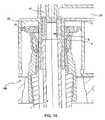
- FIG. 14 shows the connection means of the invention in a first state of a fluid communication in a longitudinal sectional view.
- FIG. 15 shows the connection means of the invention in a second state of the fluid communication in a longitudinal sectional view.
- FIG. 16 shows another perspective view of the connection means of the invention as part of a treatment apparatus.
- FIG. 17 shows another perspective view of the connection means of the invention as part of a treatment apparatus.
- FIG. 18 shows a perspective view of a connection means of the invention in a pivoted position.
- FIG. 19A shows the touch-prevention panel prior to use in a perspective view.
- FIG. 19B shows the touch-prevention panel after use in a perspective view.
- FIG. 20A shows a rinsing cap having a spiral structure in a perspective view.
- FIG. 20B shows a rinsing cap in an axially sealing design in a longitudinal sectional view.
- FIG. 21A shows a closure sleeve in a design A in a longitudinal sectional view.
- FIG. 21B shows a closure sleeve in a design B with improved drip-protection in a perspective view.
- FIG. 22A shows a longitudinal sectional view of the closure sleeve of design B in a basic position.
- FIG. 22B shows a longitudinal sectional view of the closure sleeve of design B in a closure position.
- FIG. 23A shows a longitudinal sectional view of a lateral compensation in a design A in a basic position.
- FIG. 23B shows a longitudinal sectional view of the lateral compensation of design A in a deflected position.
- FIG. 24A shows a longitudinal sectional view of a lateral compensation in a design B in a basic position.
- FIG. 24 B shows a longitudinal sectional view of the lateral compensation of design B in a pre-centering position.
- FIG. 24C shows a longitudinal sectional view of the lateral compensation of design B in a connection position.
- FIG. 25A shows a longitudinal sectional view of an embodiment of the connection means of the invention during a disinfection, a rinsing operation and/or in operation-readiness.
- FIG. 25B shows a longitudinal sectional view of an embodiment of the connection means of the invention during an emptying operation and/or at the beginning of a connecting operation.
- FIG. 25C shows a longitudinal sectional view of an embodiment of the connection means of the invention during the connection and/or a closing operation.
- FIG. 26 shows a longitudinal sectional view of a dialysis filter including a connector subassembly inside the dialysate port.
- FIG. 27 shows a flow diagram of a treatment apparatus of the invention comprising a connection means of the invention and an external functional means.
- FIG. 28 shows a rinse port in a longitudinal sectional view.
- FIG. 1 shows a connection means 100 of the invention in a longitudinal sectional view.
- the connection means 100 comprises an inner pipe 1 which is arranged—only in a preferred manner concentrically—inside an outer pipe 3 .
- the inner pipe 1 may be axially displaceable in the outer pipe 3 .
- FIGS. 2 to 4 each show a basic position of arrangements or subassemblies, respectively, which are prepared for establishing a fluid connection in accordance with the method of the invention or with the aid of the connection means of the invention.
- FIG. 2 shows a longitudinal sectional view of a connector subassembly 200 for the connection to a connection means of the invention which is not shown in FIG. 2 .
- the connector subassembly 200 is part of an external functional means, while the connection means is part of a treatment apparatus.
- the connector subassembly 200 might, however, also be present on the treatment apparatus, with the connection means in turn being present on the external functional means.
- the connector subassembly 200 comprises a connection pipe 5 having an inner lumen 7 . Inside the connection pipe 5 a closure sleeve 9 is arranged.
- the closure sleeve 9 comprises a closure collar 11 at its upper end (relative to its orientation in FIG. 2 ).
- a latching arrangement 13 in an inner wall 15 of the connection pipe 5 the closure sleeve 9 is retained in its position against a displacement, e.g. in a downward direction.
- the latching arrangement 13 comprises a thickening in the inner wall 15 of the connection pipe 5 and a recess or depression in a side wall of the closure sleeve 9 .
- the invention does, however, also encompass reversed arrangements, i.e., depression in the inner wall and thickening in the closure sleeve.
- the disclosure of such “reversed” configurations is always inherent in the framework of the presently described invention whenever it is recognizable to the skilled person that they are technically practicable.
- the latching arrangement 13 might also be configured as a clamping means (not represented) or the like.
- connection pipe 5 At its upper end (relative to the orientation in FIG. 2 ) the connection pipe 5 comprises a closure neck 17 .
- the closure neck 17 has a crenellated shape.
- a support dome 19 On the upper side of the closure neck 17 a support dome 19 is provided.
- a passage 21 On the right-hand side of the closure neck 17 (relative to the arrangement in FIG. 2 ) a passage 21 is provided.
- the passage 21 may lead to an interior of the external functional means.
- the connector subassembly 200 comprises a reception space 23 for receiving fluids.
- the connector subassembly 200 On its lower side (relative to the arrangement in FIG. 2 ) the connector subassembly 200 comprises a support ring 25 . Between an outer wall 27 of the connector subassembly 200 and the support ring 25 a latching arrangement 29 for a touch-prevention panel 31 is provided.
- FIG. 3 schematically shows a connection means 100 in accordance with the present invention in a longitudinal sectional view.
- the connection means 100 is shown in its overall arrangement as part of a treatment apparatus.
- the connection means 100 comprises an inner pipe 1 as well as an outer pipe 3 .
- the inner pipe 1 has been introduced into the outer pipe 3 .
- the inner pipe 1 comprises an inner lumen 33 . Between the outer wall 35 of the inner pipe 1 and the inner wall 15 of the outer pipe 3 , there is a gap presently designated as an outer lumen 37 of the inner pipe 1 . Both the inner lumen 33 of the inner pipe 1 and the outer lumen 37 of the inner pipe 1 are suited for receiving fluids. At its upper end (relative to the orientation in FIG. 3 ) a wall of the inner pipe 1 comprises a widening 39 . The widening 39 has a spherical configuration. As an alternative, both the entire inner pipe 1 and also its inner lumen 33 might comprise such a widening.
- connection means 100 is covered or closed by a rinsing cap 41 .
- a drive mechanism may be provided in order to be able to remove the rinsing cap 41 in an automated manner from the connection means 100 or vice versa, for example in order to establish a fluid communication with another fluid-conducting system.
- FIG. 3 parts of such a drive mechanism having the form of a rinsing cap pivotal drive mechanism 43 are shown.
- the rinsing cap pivotal drive mechanism 43 comprises a support means 45 .
- the support means 45 comprises an upper part 451 and a lower part 453 .
- the upper part 451 and the lower part 453 are fixedly connected to each other. In the basic position of FIG. 3 , the upper part 451 and the lower part 453 are aligned substantially in parallel or in a mirror-symmetrical manner relative to each other.
- the support means 45 comprises a pivotal mount 455 .
- the support means 45 is moved by means of a linear drive (not shown).
- FIG. 3 a chassis 47 of the treatment apparatus is shown.
- the chassis 47 comprises a rubber plate 49 on its upper side (relative to the orientation in FIG. 3 ) as well as on an inner side of the chassis 47 facing the rinsing cap 41 .
- the inner pipe 1 comprises a fluid port 51 for introducing fluids into the inner lumen 33 of the inner pipe 1 .
- the outer pipe 3 comprises a fluid port 53 for introducing fluids into the outer lumen 37 of the inner pipe 1 or for discharging the fluids therefrom.
- FIG. 4 shows a portion of the connection means 100 of the invention of FIG. 3 in an enlarged representation.
- the portion or detail of the connection means 100 shown in FIG. 4 serves for establishing a connection in fluid communication of the treatment apparatus and of an external functional means.
- the outer pipe 3 comprises a base body 55 .
- the outer pipe 3 comprises a head cover or head body 57 .
- the outer pipe 3 moreover comprises a sealing cover or sealing body 59 .
- the gap 61 may be a gap circling the inner pipe 1 . It may have identical dimensions in every portion of its extension. It may, however, also have different dimensions in portions thereof if the inner pipe 1 were not arranged centrally in the outer pipe 3 .
- the gap 61 is delimited laterally, or in a radial direction, by the sealing body 59 of the outer pipe 3 . Below the gap 61 there continues the outer lumen 37 of the inner pipe 1 that is accessible to fluids.
- the rinsing cap 41 comprises a fluid insert 411 as well as a mounting body 413 .
- the rinsing cap 41 is placed on or over the sealing body 59 of the outer pipe 3 , or applied over the inner pipe 1 and the outer pipe 3 .
- the sealing body 59 of the outer pipe 3 is compressed at the seal 60 with the rinsing cap 41 .
- the rinsing cap 41 or the fluid insert 411 thereof is expanded at the seal 60 .
- the rinsing cap 41 is sealed against the treatment apparatus or a treatment apparatus front, respectively, at two peripheral seals 621 and 623 .
- the rinsing cap 41 is seated flush in or on a surface 201 of the treatment apparatus.
- FIG. 5 schematically shows a connection means 100 of the invention as a part of a treatment apparatus 300 in a partial longitudinal sectional view.
- the connection means 100 carries the rinsing cap 41 .
- the treatment apparatus 300 comprises a motor, e.g. a DC motor 63 , for pivoting the rinsing cap 41 .
- the treatment apparatus 300 comprises a motor, e.g. a DC motor 65 , for displacing the connection means 100 .
- the treatment apparatus 300 comprises a dripping water drain 67 .
- the treatment apparatus 300 comprises a film potentiometer 69 for recognizing a position of the connection means 100 .
- the treatment apparatus 300 may comprise several sensors which may in a given case also be of different kinds. As is shown in FIG. 5 , the treatment apparatus 300 comprises a Hall sensor 71 for this purpose. An inlet 73 for introducing fluids into the connection means 100 leads to the interior of the connection means 100 .
- FIG. 6 shows the connection means 100 of the invention as a part of a treatment apparatus 300 from the front and above, as viewed from the side of the external functional means to be coupled or integrated.
- the connection means comprises the rinsing cap 41 .
- the inlet 73 is concealed in the present representation of the connection means 100 of the invention. Indication of the reference numeral has the purpose of indicating its position.
- the treatment apparatus 300 comprises a pivoting lever 75 .
- the rinsing cap 41 is rigidly connected to the pivoting lever 75 .
- the pivoting lever 75 comprises a magnet 77 .
- the treatment apparatus 300 is shown with two Hall sensors 51 .
- the connection means 100 is provided with a pipe connection for a passage (not shown here) towards the external functional means. This passage may serve, for example, as a return line 79 for fluids.
- FIG. 7 schematically shows a state in the course of establishing a fluid communication between a treatment apparatus 300 and an external functional means 400 with the aid of the connection means of the invention 100 .
- the arrangement is represented in a longitudinal sectional view.
- FIG. 7 shows, as it were, the first contact between the treatment apparatus 300 and the external functional means 400 in the course of establishing the fluid connection.
- the sealing body 59 of the outer pipe 3 abuts against the touch-prevention panel 31 of the connector subassembly 200 of the external functional means 400 .
- a center axis 81 of the connection pipe 5 and a center axis 83 of the inner pipe 1 are positioned at a discernible offset. Therefore, the connection pipe 5 is not yet in the desired or aspired position relative to the inner pipe 1 for establishing the fluid communication.
- a cover means 85 is provided, for example a door surface or panel.
- Such a cover means may be employed, for instance, for pressing the external functional means in the treatment apparatus as disclosed, for example, in the German patent application No. 10 2009 012 633.3 (representative's file FM19A24) having the title “Vorraumtechnischtechnisch Verbinden fürcies responded mit für An für, An extract für, etc.] [Device for connecting an external functional means to an arrangement, arrangement including a like device, and connecting method] deposited by the applicant of the present application with the German Patent and Trademark Office on Mar. 8, 2009, the relevant disclosure of which is herewith fully incorporated by way of reference.
- FIG. 8 schematically shows a longitudinal sectional view of the connection means 100 at the beginning of threading the connection pipe 5 in the outer pipe 3 .
- the outer pipe 3 comprises a leading-in funnel or guiding funnel 87 .
- the guiding funnel 87 is part of the sealing body 59 of the outer pipe 3 .
- the center axis 81 of the connection pipe 5 does not have a central alignment relative to the outer pipe 3 . It may rather be seen that the outer pipe 3 is shifted to the right along the lower side of the connector subassembly 200 , or vice versa.
- the guiding funnel 87 of the outer pipe 3 is contiguous or abuts against the touch-prevention panel 31 of the connector subassembly 200 .
- the position of the center axis 83 of the inner pipe 1 is at an offset from the center axis 81 of the connection pipe 5 .
- the connection pipe 5 has a lateral tolerance 89 in its inner lumen 7 .
- the lateral tolerance 89 preferably serves for providing a certain measure of play, for example in order to compensate inaccuracies of fit.
- the lateral tolerance 89 advantageously allows to perform threading of the inner pipe 1 in the connection pipe 5 in an easy manner and/or free from damage.
- FIG. 9 schematically shows a longitudinal sectional view of the connection means 100 at the end of threading the outer pipe 3 .
- the inner pipe 1 is partly inserted or introduced into the connection pipe 5 (or vice versa).
- the inner lumen 33 of the inner pipe 1 is in fluid communication with the inner lumen 7 of the connection pipe 5 .
- the preferred arrangement for fluid connection has, however, not been reached yet.
- the inner pipe 1 is not properly aligned yet with the connection pipe 5 .
- the center axis 83 of the inner pipe 1 and the center axis 81 of the connection pipe 5 are offset relative to each other.
- FIG. 10 shows an enlarged detail representation of a position at the beginning of threading the inner pipe 1 in the connection pipe 5 .
- the wall of the connection pipe 5 is pushed between the widening 39 of the inner pipe 1 and the sealing body 59 of the outer pipe 3 .
- FIG. 11 schematically shows the connection means 100 in a position of minimum connection of the inner pipe 1 with the connection pipe 5 .
- the inner pipe 1 is inserted into the connection pipe 5 with the widening 39 and beyond.
- the wall of the connection pipe 5 substantially fills the gap 61 between the sealing body 59 of the outer pipe 3 and the widening 39 of the inner pipe 1 .
- the center axis 81 of the connection pipe 5 and the center axis 83 of the inner pipe 1 are now coincident.
- the widening 39 pushes the connection pipe 5 apart or expands it at least locally.
- the sealing body 59 of the outer pipe 3 presses or pushes from the outside against the wall of the connection pipe 5 .
- the sealing body 59 of the outer pipe 3 pushes the touch-prevention panel 31 of the connector subassembly 200 in an upward direction in FIG. 11 , whereby the reception space 23 of the connector subassembly 200 becomes smaller, for example in comparison with the reception space shown in FIG. 2 .
- FIG. 12 schematically shows the connection means 100 in a position of maximum connection of the inner pipe 1 and the connection pipe 5 .
- any axial position is admissible. This advantageously results from the axial tolerance compensation provided with the connection means of the invention.
- the inner pipe 1 is shifted even further into the connection pipe 5 as compared with the position of FIG. 11 .
- the widening 39 is located completely inside the connection pipe 5 .
- the touch-prevention panel 31 has been shifted further in an upward direction, so that the reception space 23 has become even smaller in comparison with the reception space of FIG. 11 .
- the end side of the widening 39 is directly contiguous with the closure sleeve 9 of the connector subassembly 200 even before the condition of maximum connection is reached, and thus displaces the closure sleeve 9 in an axial direction.
- the closure collar 11 is contiguous with the closure neck 17 of the connector subassembly 200 .
- the fluidic connection and/or seal may be effected by insertion of the inner pipe 1 having the widening 39 into the connection pipe 5 .
- the connection pipe 5 is widened or expanded annularly in the location of largest diameter of the widening 39 . This may advantageously result in the creation of an annular sealing zone in which the inner wall of the connection pipe 5 is applied to the outer circumference of the largest outer diameter of the widening 39 under—preferably elastic—tensioning of material.
- such tensioning of material due to expansion may ensure a sufficient fluid-tightness of the connection against the specified differential pressures relative to the environment.
- the inner wall of the connection pipe 5 preferably has a cylindrical configuration. Relative to the diameter of the connection pipe 5 , the inner wall of the connection pipe 5 may preferably be realized with thin walls and/or a constant wall thickness. In this way, it may advantageously be possible to keep the expanding and/or sealing effect constant at any distance of insertion of the inner pipe 1 into the connection pipe 5 .
- thermoplastic materials such as polypropylene, polyamide, polycarbonate, thermoplastic composite materials including PTFE (polytetrafluoroethylene) and the like may be employed, however, without being restricted thereto. These materials may advantageously be processed at low cost by means of injection molding techniques. They may moreover possess a favorable rigidity and/or tenacity for the above-described principle of sealing involving expansion.
- connection pipe 5 encompass an inner diameter of 4 mm to 8 mm, a wall thickness of 0.4 mm to 1 mm, as well as a length of 20 mm to 40 mm.
- a pipe In general, due to its geometry a pipe predominantly has a lower expansion stiffness in the vicinity of its open mouth and/or predominantly has a higher expansion stiffness in the vicinity of the coupled end than in a central region.
- connection pipe 5 that have a distance from one or two ends of the connection pipe 5 of slightly more than one times the inner diameter.
- connection pipe 5 preferably is the connection half-assembly or the system which is realized on the side of an external functional means 400 , for instance in the form of a single-use part.
- the widening 39 may produce a seal in the external functional means.
- the widening 39 may further provide tolerance compensation.
- the widening 39 of the inner pipe 1 preferably is realized such that at least the annular region of expansion has the form of a sphere.
- the center of the sphere may be situated on a center axis or axis of symmetry 83 of the inner pipe 1 .
- the same annular geometry of contact or sealing may thus always advantageously be effected in this way.
- the same annular geometry of contact or sealing may thus always advantageously be effected in this way.
- Narrow annular sealing bars may advantageously provide redundant sealing ring zones having the same or elevated sealing pressure.
- An elastomer ring insert may advantageously bridge or shunt out or equalize small roughnesses between the sealing mates.
- the widening 39 of the inner pipe 1 may present a diameter overdimension relative to an inner diameter of the connection pipe 5 .
- a diameter overdimension preferably is in a range from 2% to 10% of the inner diameter of the connection pipe 5 .
- the inner pipe 1 having the widening 39 may be a connection half-assembly of the treatment apparatus 300 .
- connection means 100 or the inner pipe 1 , respectively, and/or the widening 39 of the inner pipe 1 preferably comprise(s) materials such as stainless steel, titanium, steels having ceramic, oxide, and/or PTFE—(polytetrafluoroethylene-) containing coatings and/or injection-moldable sintered ceramics such as zirconium oxide or are made of such materials. It is, however, equally possible to realize the connection means 100 of the invention as single-use part, e.g. by using thermoplastic resins.
- connection half-assembly in a reverse manner, i.e., the connection pipe 5 as a stiff or non-deformable component of the treatment apparatus 300 , or as a stiff or non-deformable component of the external functional means 400 .
- the connection pipe 5 is in particular preferred when the realization of thin-walled connection pipes 5 is not possible or only possible at high complexity or costs.
- the outer pipe 3 comprises a redundancy sealing bead 91 as an example of another redundant sealing security.
- a redundancy sealing bead 91 may serve for radially supporting the connection pipe 5 .
- the redundancy sealing bead 91 primarily has two purposes: Firstly, the redundancy sealing bead 91 serves for radially supporting the connection pipe 5 in order to maintain the expansion-type main seal in accordance with the invention. Secondly, the redundancy sealing bead 91 serves as a redundant secondary sealing. The O-ring shown in FIG. 12 on the left next to the redundancy sealing bead 91 serves as a spring. The redundancy sealing bead 91 may have an annular configuration.
- FIG. 12 shows a typical connection position of the connection means of the invention for a redundancy sealing bead 91 .
- the connection pipe 5 of the connector subassembly 200 is again pressed against the connection means 100 in an annular zone at the inner wall 15 of the outer pipe 3 .
- a fluidic seal may exist.
- the inner diameter of the redundancy sealing bead 91 attached to the outer pipe 3 may be selected to be about 2% to 10% smaller than the outer diameter of the substantially cylindrical and/or smooth-walled connection pipe 5 .
- At least one of the two sealing mates, the outer pipe 3 and/or the connection pipe 5 may preferably be realized to be elastic.
- connection pipe 5 in the outer pipe 3 , a radial inward compression towards the connection pipe 5 or a radial outward expansion of the redundancy sealing bead 91 may be effected in the region of the redundancy sealing bead 91 .
- connection pipe 5 is pressed against the redundancy sealing bead 91 under radial stress.
- the tensioning of material in combination with a sufficient smoothness, or in combination with a sufficient assimilation of the associated surfaces may advantageously result in fluid-tightness of the connection pipe 5 against the outer pipe 3 .
- the redundancy sealing bead 91 is preferably arranged in immediate vicinity of the widening 39 of the main seal at an axial offset of up to about one times the inner diameter of the connection pipe 5 in a direction towards the open pipe opening of the connection pipe 5 .
- the offset arrangement of the widening 39 may on the one hand ensure a continued elastic deformation capability of the connection pipe 5 both to the outside and to the inside.
- a pipe may have a general tendency to a funnel-type expansion towards the open pipe end due to being expanded. This type of expansion is advantageously also counteracted by the offset arrangement of the redundancy seal annular zone of the redundancy sealing bead 91 .
- the redundancy sealing bead 91 may be made of hard or include materials such as metals and/or ceramics, of resilient materials such as PTFE and/or POM (polyoxymethylene), and/or of elastomer materials such as, e.g., silicone rubber and the like.
- the redundancy sealing bead 91 represented in FIG. 12 is made of PTFE in one piece with the head body 57 of the outer pipe 3 .
- the PTFE material may be provided with persistent elasticity in a radial inward direction by tempering (cold stretching) and/or by being mounted against an elastic ring of elastomers and/or by means of annular springs.
- the axial pushing force required for sealing may advantageously be minimized.
- the elastic elements may advantageously cause a constant sealing effect even in the event of an admissible wear of the PTFE layer.
- connection means 100 of the invention By means of the connection means 100 of the invention, it is advantageously possible to obtain tightness monitoring and/or leakage protection.
- connection pipe 5 In the connection position of FIG. 12 , the connection pipe 5 is connected on the inside to the fluid port 51 of the inner pipe 1 in a fluid-tight manner. The connection pipe 5 is further fluid-tight against the fluid port 53 of the outer pipe 3 .
- the inner lumen 33 of the inner pipe 1 preferably serves for the regular fluid connection.
- the outer lumen 37 of the inner pipe 1 is optionally filled with gas, for example air, and/or liquid.
- the outer lumen 37 is preferably coupled to a conduit leading to the waste water branch, e.g., a dripping water drain (not shown in FIG. 12 ), via a pressure limiting valve.
- the response pressure of the pressure limiting valve may be set to be lower than the maximum liquid pressure occurring in the inner fluid connection.
- the response pressure of the pressure limiting valve may furthermore be lower than the minimum sealing pressure against the environment that may be obtained by the redundancy sealing bead 91 .
- the response pressure of the pressure limiting valve is even below the pressure of the atmosphere.
- the pressure limiting valve may eventually open and allow the leaked liquid to pass over into the waste water branch in a controlled manner. In this way it is advantageously possible to poll the switching condition of the pressure limiting valve and thus recognize a possible leakage of the main seal as soon as possible on behalf of the self-check routine prior to the beginning of the respective treatment method. In this way, it may in turn advantageously be possible to take countermeasures early on, such as replacing the external functional means 400 and/or replacing worn components of the treatment apparatus 300 .
- a vacuum to the fluid port 53 of the outer pipe 3 (e.g., when using a fluid connection under negative pressure conditions) and/or a direct connection with the drain that is open to the atmosphere (e.g., when using a fluid connection under overpressure conditions) and to perform a pressure keeping test of the inner fluid connection—in particular between inner pipe 1 and connection pipe 5 —on behalf of the self-check routine.
- the monitoring method described first in the foregoing may advantageously be performed even prior to the beginning of the actual treatment or main treatment such as, for example, a dialysis treatment. It may advantageously also be effective continuously during the main treatment.
- the monitoring method described second in the foregoing may be restricted to tightness monitoring prior to the beginning of the main treatment.
- Both fluid arrangements may advantageously ensure that treatment fluids will not leak to the environment at any point of time. Instead, possibly occurring leakage fluids are discharged into the waste water branch of the treatment apparatus 300 in a controlled manner.
- FIG. 13 is a view of a connection means 100 of the invention in a connection position.
- FIG. 14 is a longitudinal sectional view of the connection means 100 of the invention in a closed position.
- a fluid communication between the inner pipe 1 and the connection pipe 5 has been established.
- the reception space 23 is further made smaller, e.g. in comparison with the one of FIG. 12 , by sliding up the touch-prevention panel 31 .
- the closure sleeve 9 is pushed by the closure collar 11 from below (relative to the arrangement in FIG. 14 ) into the closure neck 17 .
- the closure sleeve 9 is displaced in an upward direction in FIG. 14 by displacing or shifting the connection means 100 into the closure position (with the rinsing cap being open).
- the closure sleeve 9 closes the passage 21 to the external functional means. Closing the external functional means may take place, for example, at the end of a treatment session.
- FIG. 15 is a sectional view of the connection means 100 of the invention at a maximum admissible displacement of the closure position.
- a residual gap 28 preferably remains between the touch-prevention panel 31 and the inner side of the outer wall 27 . This may advantageously contribute to safe and smooth operation.
- the reception space 23 has a minimum size. The closure sleeve 9 is again pushed further into the closure neck 17 .
- FIG. 16 is a view of a connection means 100 of the invention without a rinsing cap.
- the connection means 100 may be taken from the closure position into a rinsing position.
- the support means or support is displaced axially against the connecting direction to such a distance that the rinsing cap may be pivoted above the connection means in an axially aligned manner.
- the support or the support means is displaced in the connecting direction until a sealing connection of the connection means to the rinsing cap is obtained.
- FIG. 17 is a view of a connection means 100 of the invention in a rinsing position.
- the housing front part 93 of the treatment apparatus 300 conceals components of the connection means 100 and/or of the treatment apparatus 300 situated behind it.
- Reference numerals of concealed elements shall be indicated in the following description in order to facilitate an understanding of their co-operation.
- the rinsing position may correspond to the basic position of the connection means 100 .
- the rinsing cap 41 has been pivoted in front of the opening (of the connection means 100 ) in the housing front part 93 of the treatment apparatus 300 .
- the rinsing cap 41 is axially flush with the front side of an actor/sensor mat (not shown).
- a possibly existing ring gap between the rinsing cap 41 and the housing front part 93 of the treatment apparatus 300 may, for example, be sealed with an O-ring against penetrating fluids, in particular penetrating liquids.
- connection means 100 preferably plunges into the rinsing cap 41 such that the sealing body 59 of the outer pipe 3 , or an outer edge thereof, is sealed against an outside in the rinsing cap 41 .
- the sealing body of the outer pipe 3 When the sealing body of the outer pipe 3 is made of a composite PTFE material, it may represent the softer partner of this sealing pair. It may therefore preferably be configured such that it may advantageously be replaced without opening the treatment apparatus 300 .
- cleaning liquid is generally supplied through the inner pipe 1 and discharged through the outer pipe 3 .
- a Hall sensor e.g. a H2Conn (S 502 ) may detect the magnet 77 attached on the pivoting lever 75 .
- the axial position of a spindle nut (and thus of the connection pipe 5 of the external functional means 400 ) may be determined with the aid of the potentiometer, e.g. the linear potentiometer SPosConn (S 503 ).
- the axial position of the rinsing cap 41 may be determined based on the distance of the outer edge of the sealing body from the housing front part 93 of the treatment apparatus 300 .
- connection means 100 In order to pass over from the rinsing position into the connection position, the following sequence of movements may be executed: Initially, an axial movement of the connection means 100 together with the rinsing cap 41 against the connecting direction (to the left in FIG. 17 ) takes place. Subsequently, the connection means 100 is moved out of the rinsing cap 41 in the axial direction. The rinsing cap 41 may remain in its position. Then a pivoting movement of the rinsing cap 41 may take place to such an extent as to enable a free movement of the connection means 100 in the connecting direction. At last, the connection means 100 may be moved out of the front plane of the treatment apparatus 300 in an axial direction and into the external functional means 400 .
- connection means 100 may be displaced axially in the connecting direction. Due to the pivoting lever 75 pivoted open, the rinsing cap 41 preferably exposes an opening in the housing front part 93 . The connection means 100 may be displaced in a forward direction. The connection means 100 may now penetrate into the connection pipe 5 of the connector subassembly 200 of the external functional means 400 .
- FIGS. 1 to 18 In order to facilitate understanding of the described embodiments, reference numerals are indicated, the general description or association of which may predominantly be found in FIGS. 1 to 18 .
- the present invention provides a particular lateral mobility and/or pre-centering.
- External functional means 400 may comprise a multiplicity of functional means that simultaneously need to be aligned in three dimensions. Frequently, it is intended to align these functional means, e.g., connectors, sensors, actors and the like, by or relative to corresponding functional means and/or arrangements of treatment apparatuses 300 .
- a basic alignment and/or fixation of the entire external functional means 400 may usually be effected with the aid of a separate means.
- a centering latching of the external functional means 400 to the chassis 47 of the treatment apparatus 300 and/or a fixation of the external functional means 400 by pressing and/or installation in form closure connection between the chassis 47 of the treatment apparatus 300 is performed.
- a rubber plate 49 and/or a door panel may be used as a cover means 85 (see, e.g., FIG. 3 ).
- connection means 100 and the connector subassembly 200 When two external functional means 400 are to be taken into fluid communication with each other, the orientation among the connection means 100 and the connector subassembly 200 , or among a connection means 100 of a first external functional means 400 and a connector subassembly 200 of a second external functional means 400 may take place directly by means of the inner pipe 1 and of the outer pipe 3 of the connection means 100 and the connection pipe 5 of the connector subassembly 200 .
- connection of the connection means 100 and/or of the connector subassembly 200 to a port of a treatment apparatus 300 may, for example, be effected with the aid of thread and/or a bayonet catch and/or via a pivotal yoke (as, e.g., in the case of the rinse port of the current 5008 dialysis machine by the company Fresenius Medical Care, Bad Homburg, Germany).
- a (further) lateral offset of the connection systems could additionally occur in the prior art owing to tolerances or manufacture.
- connection means 100 and the connector subassembly 200 could be taken into the connection positions at a sufficiently low lateral deviation of the respective associated connection axes (e.g., center axes 81 , 83 ).
- the maximum admissible lateral positional deviation of a connection opening, e.g., of the inner pipe 1 , relative to, e.g., the connection opening of the connection pipe 5 e.g., may be about +/ ⁇ 0.2 mm.
- connection means 100 and the connector subassembly 200 in particular the connection pipe 5 of the connector subassembly 200 , might still achieve mutual centering under a sufficiently low lateral force of, for instance, less than 10 N through a flexure in the connection position without causing leakages.
- connection pipes inner pipe 1 , connection pipe 5 and outer pipe 3
- they preferably require correspondingly configured guiding funnels 87 in combination with an equally high lateral mobility of at least one in a case of two connection partners, i.e., of the connection means 100 and/or the connector subassembly 200 relative to each other.
- This lateral mobility may preferably be guaranteed by a pivotal mount 455 of the connection means 100 of the invention relative to the chassis 47 of the treatment apparatus 300 .
- the represented mounting type advantageously results in a sufficient lateral mobility of the connection opening of the inner pipe 1 of the connection means 100 of the invention relative to the chassis 47 of the treatment apparatus 300 .
- the outer pipe 3 possesses a spherical shape which is mounted rotatably and/or with little play in corresponding hemispherical sockets, i.e., the upper part 451 and the lower part 453 of the support means 45 (see FIG. 3 and FIGS. 24A-C ).
- connection means 100 of the invention may also be used in a horizontal position under the influence of gravity, and as the lateral mobility means usually is subject to friction and therefore not automatically resetting, a pre-centering means is preferably used in accordance with the invention.
- the pre-centering means preferably aligns at least one of the connection means 100 of the invention and/or of the connector subassembly 200 in a tolerance center prior to a renewed connection.
- pre-centering means may preferably ensure that a maximum lateral force among the connection means 100 of the invention and the connector subassembly 200 during the connection is limited to a predetermined value, for example somewhat less than about 10 N.
- connection means 100 of the invention and the connector subassembly 200 might already adopt an excessive laterally deviating position prior to the connection due to their lateral mobility.
- a correspondingly larger guiding funnel 87 might then be necessary which would, however, generally be undesirable as the structural size of the arrangement of the connection means 100 of the invention would then increase in an unfavorable manner.
- FIGS. 23A and 23B show an embodiment of pre-centering through the intermediary of springily deflectable tongues or flexible pre-centering tongues 95 (preferably three tongues).
- the flexible pre-centering tongues 95 may bring the connection means 100 into a zero position or basic position, respectively, and at the same time exert a sufficiently low lateral force even in the event of a maximum deflection.
- Pre-centering stops 97 may guarantee a limitation of the lateral deflection to the maximum admissible value (in a given case depending on the dimensions of the arrangement of the guiding funnel 87 ).
- FIGS. 24A to 24C show an alternative arrangement in which the pivotal mount 455 is realized as balanced scales at an horizontal orientation. From the basic position of FIG. 24A into an intermediate position of FIG. 24B , the outer pipe 3 is guided by a pre-centering tube 99 until an opening of the inner pipe 1 of the connection means 100 of the invention exhibits an overlap with the guiding funnel 87 to the mouth of the connection pipe 5 of the connector subassembly 200 .
- the pre-centering tube 99 gets disengaged, so that no resetting spring forces may act laterally on the connection partners as in previously known arrangements.
- the fluidic connection conduits of the inner lumen 33 of the inner pipe 1 and of the outer lumen 37 of the inner pipe 1 are realized as easily movable and easily bendable tube conduits, in a particularly preferred manner of silicone rubber.
- connection means 100 An arrangement of the fluidic connection conduits as closely as possible near an articulation center point of the pivotal mount 455 is preferred in such a case.
- connection means 100 it may be particularly advantageous to provide the tube conduits or portions thereof with a spiral form.
- the present invention provides a lateral, axial and/or angular fine alignment and/or a tolerance compensation.
- tolerance compensation shall in the following be explained with reference to a representation of the movement processes during the connection.
- connection means 100 e.g., according to FIG. 4 or FIG. 24A
- a coupling position e.g. according to FIG. 7
- FIG. 24B Starting from a basic position of the connection means 100 (e.g., according to FIG. 4 or FIG. 24A ) or from a coupling position (e.g. according to FIG. 7 ) to a position according to FIG. 24B , the pre-centering described in the foregoing is applied.
- connection pipe 5 has penetrated minimally into the guiding funnel 87 of the outer pipe 3 , so that the guiding funnel 87 may fulfill the essential tasks of further centering the connection means 100 or the inner pipe 1 and the connector subassembly 200 or the connection pipe 5 .
- the last part of lateral centering may be carried out by the widening 39 of the inner pipe 1 after an initial contact with the rounded jacket surface of the inner wall 7 of the connection pipe 5 ; see, for example, FIG. 10 .
- connection means 100 and of the connector subassembly 200 From this position on, fine centering is completed for all further introduction paths of the connection means 100 and of the connector subassembly 200 .
- the preferred globularly spherical shape of the widening 39 in combination with the outer diameter of the inner pipe 1 and in combination with the inner diameter of the connection pipe 5 having a relative larger size by about 5% to 30% may be suited to allow a complete lateral tolerance compensation with the aid of the pivoting movement of the treatment apparatus 300 as described in the foregoing.
- the maximum angular offset between the connector axes or center axes 81 , 83 produced in the process advantageously does not result in a mechanical collision or in a leakage of the main seal and/or of the redundancy seal.
- the tolerance of the axial offset between the connection means 100 of the invention and the connector subassembly 200 is about +/ ⁇ 1.5 mm. This tolerance dimension may lead to reduced complexity of manufacture of the participating structures.
- connection system of the treatment apparatus 400 including the drive mechanism or drive unit, should as far as possible be adapted for assembly and/or replacement without individual calibration.
- the drive mechanisms of the treatment apparatus 400 to have referencing means, path measuring means and/or drive units that are as simple and low-cost as possible.
- the elements of the two connection systems may be adapted such that an axial tolerance of about +/ ⁇ 1.5 mm is admissible for any relevant positions of the connector arrangement.
- FIGS. 12 , 14 and 15 illustrate how both a secure connection and a secure open position or closure position of the connector subassembly 200 of an external functional means 400 may be ensured in all of the relevant connection positions.
- the present invention provides an optimized protection for the connector subassembly 200 of an external functional means 400 against touch and/or cough.
- the optimized protection against touch and/or cough may in particular be advantageous for the fluid-conducting inner region of the connection pipe 5 that is critical in terms of hygiene.
- the present invention further allows an improved sterilization capability, in particular an improved gas sterilization capability.
- the mouth of the conventional connector or of the conventional connection means is not protected any more against the entry of foreign matters by air-borne transmission, for instance due to coughing or sneezing.
- connection pipe 5 of the external functional means 400 has been known to be generally equipped with another external tube structure, compared to which the actual connection pipe 5 is receded so far that a human finger and the end face of the connection pipe 5 may not get in direct contact in the case of inadvertent touch.
- a new approach in accordance with the present invention is represented by the touch-prevention panel 31 (in FIGS. 19A and 19B ) in the positions according to FIGS. 7 to 12 and 14 and 15 .
- the touch-prevention panel 31 is retained on the external functional means 400 by means of a latching arrangement 29 (e.g., FIG. 2 ) from its assembly until insertion of the external functional means 400 in the treatment apparatus 300 .
- the touch-prevention panel 31 covers the end face of the connection pipe 5 with segmented and/or bendable segments. As a result, the mouth of the connection pipe 5 may advantageously not be touched and contaminated. Instead, it may advantageously be innocuous to touch the touch-prevention panel 31 , for instance with one finger.
- the touch-prevention panel 31 is propelled by the outer pipe 3 and advanced further.
- the bending segments fold in such a way that mechanical contact between outer surfaces of the touch-prevention panel 31 and the surfaces of the connection pipe 5 and/or the surfaces of the inner pipe 1 and/or the funnel surfaces of the outer pipe 3 may advantageously not come about at any point of time.
- the touch-prevention panel 31 may be configured in such an angularly tolerant manner that an angle in the axial direction or direction of center line between the connection means 100 and the connector subassembly 200 of not equal to zero may be allowed without impairing the function discussed.
- the reception space 23 may be configured to be sufficiently spacious or amply for being able to accommodate the touch-prevention panel 31 in any position of the connection pipe 5 while involving low forces.
- the touch-prevention panel 31 does advantageously not interfere with the known methods of gas sterilization.
- the touch-prevention panel 31 may advantageously be manufactured cost-efficiently of thermoplastic materials by injection molding.
- the position of the touch-prevention panel 31 which is now not perceivable or seen on the surface of the external functional means any more, may signal to the user that the external functional means 400 has already been used.
- the touch-prevention panel 31 advantageously need not be removed in contrast with a conventional closure cap and may guarantee unfailing touch protection for the connection opening.
- connection assembly or of the connection means 100 of the invention, also against coughing or transfer of foreign matter droplets via the air may advantageously be ensured.
- the end side of the free end 6 of the connection pipe 5 represents a potential contamination zone.
- a peripheral internal chamfer 8 or internal rounding is provided at the free end 6 of the connection pipe 5 .
- the internal chamfer 8 preferably does not contact the widening 39 . Only the transitional area of the internal chamfer 8 or of the rounding to the smooth pipe portion of the connection pipe 5 contacts the widening 39 of the inner pipe 1 , so that germs possibly present in the contamination zone may not be carried over into the connection pipe 5 .
- This fine centering may advantageously allow or favor a first contact of relevant surfaces of the connection pipe 5 and/or of the inner pipe 1 that is admissible in terms of hygiene.
- connection pipe 5 may advantageously be prevented even if a contamination of the end face of the connection pipe 5 or of the funnel surface, or of the guiding funnel 87 of the outer pipe 3 might nevertheless have occurred.
- the present invention therefore provides a protection of the connector subassembly 200 against reuse and/or trickling out.
- an improved gas sterilization capability may in turn advantageously be ensured.
- the present invention provides a protection of the connector subassembly 200 against reuse and/or trickling out.
- an improved gas sterilization capability may in turn advantageously be ensured.
- closure sleeves 9 for example according to FIGS. 21A , 21 B, 22 A, 22 B as well as 26 .
- FIGS. 22A and 22B a closure sleeve 9 with an integrated drip-protection element is shown.
- the drip-protection element is obtained by providing several pipe portions in a concentrically nested configuration, thereby creating narrow ring gaps which “suck in” drops by capillary effect and thus prevent them from trickling out.
- a closure sleeve 9 having such a construction may be used in a multiplicity of quite different external functional means (disposables), whenever the trickling out of liquid may occur following disconnection. In particular a use in the dialysate ports of dialyzers is conceivable.
- FIG. 26 shows an end cap of a dialyzer with inserted closure sleeve 9 . It is conceivable to use the closure sleeve 9 shown in FIGS. 22A and 22B as a retrofitting kit for dialyzers that are already commercially available.
- the closure sleeve 9 having an integrated drip-protection element is initially opened so that gas sterilization and/or vapor sterilization may be performed. It is closed irreversibly after the end of the single use of the external functional means, with the drip-protection element preventing liquid drops from trickling out from the connection piece.
- FIG. 22A shows the flow passage position
- FIG. 22B shows the closure position
- closure sleeve 9 may be made of the same low-cost thermoplastic materials as the remaining constituent parts of the external functional means 400 . It may be retained by the latching arrangement 13 .
- the initial arrangement may advantageously allow any form of gas sterilization in a particularly simple and effective manner.
- connection means 100 of the treatment apparatus 300 of the two connection systems may be telescoped further in, whereby the closure sleeve 9 arrives in the closure position.
- connection pipe 5 of the external functional means 400 may advantageously result in a liquid-tight and/or non-releasable expansion-type seal of the connection pipe 5 of the external functional means 400 between the associated topologies of closure neck 17 with closure collar 11 .
- a reuse may hereby advantageously be precluded and may also be recognized securely in the framework of the initial test following installation of the external functional means 400 (e.g., pressure keeping test).
- the treatment apparatus 300 and/or the external functional means 400 are advantageously not damaged upon attempted reuse.
- connection means 100 and the connector subassembly 200 are disconnected, a residual space including a residual liquid that possibly should not leak to the environment still remains in the connection pipe 5 .
- This capillary design may be integrated directly in the connection pipe 5 in the case of the known rinsing connector or on-line connector.
- a closure sleeve may be omitted altogether in this application.
- the number of constituent parts of the connector is reduced to only two parts while guaranteeing the gas sterilization capability in contrast with conventional means.
- Another advantageous application of the protection against reuse and of the protection against trickling out may result from the dialysate ports of the dialysis filter in accordance with FIG. 26 .
- closure caps usually had to be shipped jointly and installed manually after use in order to achieve a protection against trickling out of residual dialyzing liquid after use.
- closure caps are particularly inconvenient because they need to be disposed of in accordance with regulations following their removal, and where necessary have to be replaced with new, sterile caps.
- the realization of the inner pipe 1 in accordance with the invention and the latched inserted closure sleeve 9 may advantageously result in a dialysis filter which may be fully compatible with the customary dialysis filters with regard to the Hansen connector geometry and/or with regard to the connections in connection with filter manufacture.
- a utilization in any dialysis filter on the market is conceivable.
- the treatment of the dialysis filter by liquid, gas and/or vapor during manufacture is advantageously furthermore possible without any restrictions.
- a mixed use of filters with and without closure sleeve 9 may equally be ensured through corresponding realization of the connection means 100 relative to the Hansen connector geometry.
- the present invention thus provides an optimized protection against reuse and/or a protection against trickling out with optimized handling.
- the one of the two drive mechanisms is the linear drive for the main connecting movement which admits not only two positions but at least the three positions of basic position, connection position and closure position, and also provides further positions with a corresponding connection technique as described in the foregoing.
- the second drive complex relates to the drive mechanism of the movements necessary for placing and removing the closure cap or rinsing cap 41 .
- a combined pivotal and/or lifting drive which is electromotorically driven may preferably and advantageously be utilized.
- Other types of movement and actuation such as an oblique slide movement or a drive by means of pneumatic cylinders, are equally encompassed by the invention.
- FIG. 4 shows a radial seal which may advantageously do away completely with elastomer sealing rings (having inherent dead-space problems).
- At least one of the two sealing mates (the sealing body 59 of the outer pipe 3 or the fluid insert 411 of the rinsing cap 41 ) is preferably manufactured in one piece of a material that is suitable for sealing as well as for configuring the rinsing space such as, for example, PTFE.
- the elastic resilience necessary for sealing may be ensured through a resilient implementation of the sealing zone and/or through an additional reset spring support, for example through an elastomer ring acting in the direction of sealing and/or through correspondingly acting spring constructions (known from the field of rotary shaft seals).
- FIG. 20B Another variant of sealing the rinsing cap or closure cap against the outer pipe 3 is the axially sealing design shown in FIG. 20B : this involves a fluid insert 411 of elastomer or of PTFE which is placed in an axially sealing manner on the end face of the outer pipe 3 .
- a fluid insert 411 of elastomer or of PTFE which is placed in an axially sealing manner on the end face of the outer pipe 3 .
- there there preferably are substantially no more of the typical dead spaces mentioned before.
- there may additionally be particularly good endurance against wear because such an axial seal may automatically adapt axially and angularly to the sealing mate.
- Another advantage of this technique may consist in the fact that the partially emptied inner space of the connection means 100 in the region of the widening 39 of the inner pipe 1 substantially does not have a coherent ring of liquid any more when the closure cap or the rinsing cap 41 is removed, and that also the space in front of the end face of the inner pipe 1 is partially emptied from liquids.
- the mounting body 413 of the rinsing cap 41 in FIG. 4 is connected to the rinsing cap pivotal drive mechanism 43 by a thread, latch-insertion or bayonet catch. Moreover, the seal of the mounting body 413 against the chassis 47 of the treatment apparatus 300 or against the rubber plate 49 is preferably effected in a radially sealing manner.
- the mounting body 413 furthermore comprises at least one means for transmitting the forces and movements required for disassembling. In a preferred manner this is a groove for disassembling the mounting body 413 which is advantageously adapted for easy and simple operation such as, for example, by means of a coin.
- the user may now advantageously take out the rinsing cap 41 without further dismantling of the mechanism and subject both the rinsing cap 41 and the end space of the connection means 100 to a revision, for example.
- the surroundings of the head body 57 of the outer pipe 3 are accessible.
- At the head body 57 of the outer pipe 3 there are several recesses or depressions present on the outside on which a ring wrench tool may attack.
- connection means 100 of the invention advantageously includes a complete protection against touch and/or cough of all the regions that are relevant in terms of hygiene.
- the rinsing cap 41 is mounted in a liquid-tight manner against the chassis 47 of the treatment apparatus 300 or against the rubber plate 49 .
- the first operation of refitting the treatment apparatus 300 with the external functional means 400 may include fixation of the external functional means 400 in front of the rinsing cap 41 in the basic position.
- any contact with the regions that are relevant in terms of hygiene may advantageously be precluded.
- the rinsing cap 41 is drawn off behind the tight cover through the external functional means 400 from the connection means 100 while being inaccessible for touch and for drops of liquid from the surroundings, and pivoted into a further inaccessible space behind the front of the treatment apparatus 300 .
- the external functional means 400 preferably remains in this covering position.
- FIGS. 25A to 25C show a particularly optimized design and type of movement of the connection means of the invention 100 . Particularly in a horizontal connection assembly, this arrangement may achieve further raised demands with regard to low losses of residual liquid and/or with regard to securing freedom from germs.
- FIG. 20A shows a fluid insert 411 of the rinsing cap 41 having a particularly optimized configuration of flow space. Due to a substantially conical contour conformation in combination with spiral-shaped redirecting grooves, the flow exiting from the inner pipe 1 during disinfection and/or rinsing is redirected, preferably with low losses, to the lateral sealing regions between outer pipe 3 and rinsing cap 41 and thereby shifted to a rotational flow.
- the flow space through the optimized conformation was configured to be particularly narrow in order to be able to ensure overall high flow velocities and good fluid exchange.
- FIGS. 25A-C show the components of inner pipe 1 , outer pipe 3 , and rinsing cap 41 for the further optimized design.
- the outer pipe 3 is now configured to be axially movable relative to the inner pipe 1 .
- this shifting capability is preferably realized with the aid of the shown bellows arrangement 105 of a plastics material such as PTFE.
- a passage 101 is arranged which merges in the direction of return flow between two inner ring beads 107 and 109 which are capable of forming a switchable flow throttle due to the shifting capability of the inner pipe 1 relative to the outer pipe 3 in combination with corresponding diameter ratios relative to the sealing head or sealing body 59 .
- At least one further passage 103 is located, in a preferred manner also in a lowest location, in the rinsing cap 41 .
- the outer pipe 3 comprises two external ring beads 111 and 113 .
- FIG. 25A shows the locations of these components during disinfection, rinsing and operation readiness.
- the rinsing cap 41 is inserted in the outer pipe 3 to a maximum depth.
- the external ring bead 111 serves as a final seal against the environment.
- the further external ring bead 113 serves as a stripping means for possible encrustations in the region of the ring bead 111 while forming a flow redirection in this location for disinfection and rinsing.
- a flow takes place through the rinsing cap 41 , through the passage 103 in the rinsing cap 41 into the annular region between the external ring beads 111 , 113 , into the passage 101 in the outer pipe 3 , and from there into the outflow space behind the sealing body or sealing head.
- the mouth-side region of the outer pipe 3 is advantageously subjected to particularly intense rinsing action, wherein the further external ring bead 113 is cleaned from two sides, while the external ring bead 111 is rinsed on its side towards the annular region.
- the outer pipe 3 advantageously remains disinfected, well-rinsed and/or free from possible deposits in a particularly large region extending as far as the external ring bead 111 .
- FIG. 25B shows the positions of the components during the processes of emptying and at the beginning of the subsequent connecting operations to the connection pipe 5 of the connector subassembly 200 .
- the inner pipe 1 moves a further distance away from the end face of the outer pipe 3 . This results in approximate sealing between the further inner ring bead 109 and the outer diameter of the sealing head.
- the lumen of the outer pipe 3 is now coupled to the waste water network of the treatment apparatus 300 , either directly or via a conveying means.
- the inner pipe 1 is connected, either directly or via a conveying means, to a gas port.
- the liquid is discharged towards the waste water network by generating a pressure difference or by activating a conveying means.
- the relevant spaces in the mouth region of the connection means 100 and of the rinsing cap 41 are freed from liquid to such a complete degree or extent that only a small film of residual liquid remains on the surfaces, which can not result in a leakage of residual liquid to the environment any more when the rinsing cap 41 is drawn off later on.
- the inner pipe 1 is particularly far away or far removed from the end face of the outer pipe 3 and from the rinsing cap 41 .
- the entire mouth region that is of relevance during the following processes is freed virtually completely of liquid or movable residual liquid.
- the inner pipe 1 which is far receded and which is particularly relevant for the subsequent sterile connection from the point of time immediately prior to withdrawal of the rinsing cap 41 until completion of the following connecting operations, is provided with a particularly effective protection both against touch and against possible contaminations with non-sterile or soiling substances, in particular drops of liquid, which may during the subsequent rinsing cap and connection movements enter the mouth region of the internal connector subassembly 200 which is then open against the non-sterile environment.
- the inner pipe is particularly far removed from the non-sterile environment of the treatment apparatus 300 .
- FIG. 25C shows the optimized design in the position of completed connection until the final change of position into the closure position of the closure sleeve 9 .
- the inner pipe 1 is increasingly displaced in a forward direction towards the end face of the outer pipe 3 .
- both external ring beads 111 and 113 seal against the cylindrical wall of the reception space 23 .
- the functionalities of the outer lumen 37 in combination with the redundant seal and/or in combination with the examination of tightness are maintained.
- the inner pipe 1 may increasingly be displaced towards the end face of the outer pipe 3 and thus further on than in a rigid arrangement of the inner pipe 1 relative to the outer pipe 3 .
- Each ring bead may preferably be produced as an inserted sealing ring of elastomer material coated with PTFE.
- FIG. 27 schematically shows the position of the connection means 100 of the invention in a process flow chart of a dialysis machine as a treatment apparatus 300 including dialysate circuit 500 and extracorporeal blood circuit 600 .
- the extracorporeal blood circuit 600 comprises an external functional means 400 which is exemplarily shown as a blood treatment cassette.
- a blood treatment cassette is described, for example, in the German Patent Application No. 10 2009 018 664.6 (representative's file FM19A27) and German Patent Application No. 10 2009 024 468.9. (09/33-d01 DE; FM19B27) filed by the applicant of the present application with the German Patent and Trademark Office on Apr. 23, 2009 and on Jun.
- the external functional means 400 comprises the connector subassembly 200 as an integral constituent part.
- the connection means 100 and the connector subassembly 200 form the substituate connection from the dialysis machine to the blood treatment cassette.
- FIG. 27 the connection means 100 and the connector subassembly 200 are represented in the non-connected state.
- FIG. 28 shows a rinse port 700 in a longitudinal sectional view.
- the rinse port 700 comprises a realization of both connector subassemblies or connection half-assemblies, i.e., both the connector subassembly 200 and also the connection means 100 .
- Such an arrangement is particularly used for applications in which a connection is achieved manually and/or pre-centering is achieved directly through the intermediary of the connector subassemblies and/or additional means for lateral tolerance compensation are omitted and/or the internal connector subassembly as well as the external connector subassembly are equally realized as disposables and/or a closure sleeve may be omitted because the capillary drip-protection element is already integrated integrally or by material connection, respectively, in the connection pipe of the external connector subassembly while a closure sleeve as drip-protection element is not required due to the low pressures in this location at which possible residual liquids are banked up at the external connector subassembly.
- FIG. 28 furthermore illustrates that both connector subassemblies, each taken for itself, are provided with an effective classical touch protection through the intermediary of retracted connection-relevant inner connectors (inner pipe and connection pipe).
- connection means 200 connector subassembly of external functional means 201 surface of treatment apparatus 300 treatment apparatus 400 external functional means 500 dialysate circuit 600 extracorporeal blood circuit 700 rinse port 1 inner pipe 3 outer pipe 5 connection pipe 6 free end of the connection pipe 7 inner lumen of the connection pipe 8 internal chamfer 9 closure sleeve 11 closure collar 13 latching arrangement of the closure sleeve 15 inner wall of the outer pipe 17 closure neck 19 support dome 21 passage 23 reception space 25 support ring 27 outer wall of the connector subassembly 28 residual gap 29 latching arrangement touch-prevention panel 31 touch-prevention panel 33 inner lumen of inner pipe 35 outer wall of inner pipe 37 outer lumen of inner pipe 39 widening of inner pipe 41 rinsing cap 411 fluid insert 413 mounting body 43 rinsing cap pivotal drive mechanism 45 support means 451 upper part 453 lower part 455 pivotal mount 47 chassis of a treatment apparatus 49 rubber plate 51 fluid port inner pipe 53 fluid port outer pipe 55 base body of outer pipe 57 head body of outer pipe
Landscapes
- Health & Medical Sciences (AREA)
- Heart & Thoracic Surgery (AREA)
- Engineering & Computer Science (AREA)
- Public Health (AREA)
- Anesthesiology (AREA)
- Biomedical Technology (AREA)
- Hematology (AREA)
- Life Sciences & Earth Sciences (AREA)
- Animal Behavior & Ethology (AREA)
- General Health & Medical Sciences (AREA)
- Veterinary Medicine (AREA)
- Pulmonology (AREA)
- Vascular Medicine (AREA)
- Epidemiology (AREA)
- Cardiology (AREA)
- General Engineering & Computer Science (AREA)
- Mechanical Engineering (AREA)
- External Artificial Organs (AREA)
- Apparatus For Disinfection Or Sterilisation (AREA)
- Infusion, Injection, And Reservoir Apparatuses (AREA)
Priority Applications (1)
| Application Number | Priority Date | Filing Date | Title |
|---|---|---|---|
| US12/765,933 US8991876B2 (en) | 2009-04-23 | 2010-04-23 | Connection means and method for connecting at least two fluid-conducting medical-technical systems, as well as medical-technical apparatus |
Applications Claiming Priority (8)
| Application Number | Priority Date | Filing Date | Title |
|---|---|---|---|
| DE102009018664 | 2009-04-23 | ||
| DE102009018664.6 | 2009-04-23 | ||
| DE102009018664A DE102009018664A1 (de) | 2009-04-23 | 2009-04-23 | Externe Funktionseinrichtung, Blutbehandlungsvorrichtung zum Aufnehmen einer erfindungsgemäßen externen Funktionseinrichtung, sowie Verfahren |
| US18568709P | 2009-06-10 | 2009-06-10 | |
| DE102009024575A DE102009024575A1 (de) | 2009-04-23 | 2009-06-10 | Verbindungseinrichtung und Verfahren zum Konnektieren wenigstens zweier fluidführender medizinitechnischer Systeme, sowie medizintechnische Vorrichtung |
| DE102009024575.8 | 2009-06-10 | ||
| DE102009024575 | 2009-06-10 | ||
| US12/765,933 US8991876B2 (en) | 2009-04-23 | 2010-04-23 | Connection means and method for connecting at least two fluid-conducting medical-technical systems, as well as medical-technical apparatus |
Publications (2)
| Publication Number | Publication Date |
|---|---|
| US20100270792A1 US20100270792A1 (en) | 2010-10-28 |
| US8991876B2 true US8991876B2 (en) | 2015-03-31 |
Family
ID=42991440
Family Applications (1)
| Application Number | Title | Priority Date | Filing Date |
|---|---|---|---|
| US12/765,933 Active 2032-05-10 US8991876B2 (en) | 2009-04-23 | 2010-04-23 | Connection means and method for connecting at least two fluid-conducting medical-technical systems, as well as medical-technical apparatus |
Country Status (7)
| Country | Link |
|---|---|
| US (1) | US8991876B2 (de) |
| EP (2) | EP3127565B1 (de) |
| JP (1) | JP5574552B2 (de) |
| CN (2) | CN106247052B (de) |
| DE (1) | DE102009024575A1 (de) |
| PL (1) | PL2421585T3 (de) |
| WO (1) | WO2010121751A2 (de) |
Cited By (2)
| Publication number | Priority date | Publication date | Assignee | Title |
|---|---|---|---|---|
| US20180252337A1 (en) * | 2015-09-07 | 2018-09-06 | Haydale Composite Solutions Ltd. | Collar assesmbly |
| US20220105335A1 (en) * | 2020-10-07 | 2022-04-07 | Fresenius Medical Care Deutschland Gmbh | Disposable and System with a Port |
Families Citing this family (34)
| Publication number | Priority date | Publication date | Assignee | Title |
|---|---|---|---|---|
| US6695817B1 (en) | 2000-07-11 | 2004-02-24 | Icu Medical, Inc. | Medical valve with positive flow characteristics |
| MX2007005324A (es) | 2004-11-05 | 2007-06-25 | Icu Medical Inc | Conector medico de agarre suave. |
| US8454579B2 (en) | 2009-03-25 | 2013-06-04 | Icu Medical, Inc. | Medical connector with automatic valves and volume regulator |
| KR101753134B1 (ko) | 2009-04-23 | 2017-07-03 | 프레제니우스 메디칼 케어 도이칠란드 게엠베하 | 외부 기능 장치, 이 외부 기능 장치를 수용하기 위한 혈액 처리 장치 및 방법 |
| USD644731S1 (en) | 2010-03-23 | 2011-09-06 | Icu Medical, Inc. | Medical connector |
| US8758306B2 (en) | 2010-05-17 | 2014-06-24 | Icu Medical, Inc. | Medical connectors and methods of use |
| DE102010032179A1 (de) * | 2010-07-23 | 2012-01-26 | Fresenius Medical Care Deutschland Gmbh | Konnektor, medizintechnische Behandlungsvorrichtung, medizintechnische Funktionseinrichtung sowie Verfahren |
| DE102010032181A1 (de) | 2010-07-23 | 2012-01-26 | Fresenius Medical Care Deutschland Gmbh | Ankoppeleinrichtung, Konnektor, medizintechnische Funktionseinrichtung, medizintechnische Behandlungsvorrichtung sowie Verfahren |
| US9861733B2 (en) | 2012-03-23 | 2018-01-09 | Nxstage Medical Inc. | Peritoneal dialysis systems, devices, and methods |
| JP6049685B2 (ja) | 2011-03-23 | 2016-12-21 | ネクステージ メディカル インコーポレイテッド | 腹膜透析使い捨てユニット、コントローラ、腹膜透析システム |
| ITRM20120239A1 (it) * | 2012-05-24 | 2013-11-25 | Glomeria Therapeutics S R L | Dispositivo di connessione |
| DE102013001438B4 (de) | 2013-01-29 | 2017-08-24 | Fresenius Medical Care Deutschland Gmbh | Medizinische Vorrichtung mit einer Buchsen-Einheit zum Anschluss einer Stecker-Einheit einer Vorrichtung zur Bereitstellung von medizinischen Flüssigkeiten |
| AU2014364218B2 (en) | 2013-12-11 | 2019-06-06 | Icu Medical, Inc. | Check valve |
| DE102014103490A1 (de) | 2014-03-14 | 2015-09-17 | Fresenius Medical Care Deutschland Gmbh | Blutbehandlungskassette mit Folienventil und elastischem Abstandhalter sowie Blutbehandlungsvorrichtung |
| DE102014103491A1 (de) | 2014-03-14 | 2015-09-17 | Fresenius Medical Care Deutschland Gmbh | Blutbehandlungskassette mit Folienventil und unelastischem Abstandhalter sowie Blutbehandlungsvorrichtung |
| USD793551S1 (en) | 2014-12-03 | 2017-08-01 | Icu Medical, Inc. | Fluid manifold |
| USD786427S1 (en) | 2014-12-03 | 2017-05-09 | Icu Medical, Inc. | Fluid manifold |
| DE202016102660U1 (de) | 2016-05-19 | 2016-06-10 | Fresenius Medical Care Deutschland Gmbh | Externe Funktionseinrichtung, Blutbehandlungsvorrichtung zum Aufnehmen einer erfindungsgemäßen externen Funktionseinrichtung |
| WO2018237375A1 (en) | 2017-06-24 | 2018-12-27 | Nxstage Medical, Inc. | Peritoneal dialysis fluid preparation and/or treatment devices methods and systems |
| CA3092575A1 (en) | 2018-02-28 | 2019-09-06 | Nxstage Medical, Inc. | Fluid preparation and treatment devices, methods, and systems |
| CN109866424A (zh) * | 2019-03-15 | 2019-06-11 | 西安增材制造国家研究院有限公司 | 一种大尺寸颗粒塑料3d打印机防滴料喷嘴 |
| DE102020106590A1 (de) | 2020-03-11 | 2021-09-16 | Fresenius Medical Care Deutschland Gmbh | Konnektionselement und Konnektionssystem für eine Blutbehandlungsvorrichtung |
| DE102020106595A1 (de) | 2020-03-11 | 2021-09-16 | Fresenius Medical Care Deutschland Gmbh | Konzentratbehälteradapter und Konnektorgehäuse zur Anbindung an eine Blutbehandlungsvorrichtung |
| DE102020106593A1 (de) | 2020-03-11 | 2021-09-16 | Fresenius Medical Care Deutschland Gmbh | Reinigungsvorrichtung und Reinigungssystem für eine Blutbehandlungsvorrichtung |
| DE102020114988A1 (de) | 2020-06-05 | 2021-12-09 | Fresenius Medical Care Deutschland Gmbh | Verfahren zur Diskonnektion |
| DE102020126226A1 (de) | 2020-10-07 | 2022-04-07 | Fresenius Medical Care Deutschland Gmbh | Disposable und System mit einem Port |
| DE102020126224A1 (de) | 2020-10-07 | 2022-04-07 | Fresenius Medical Care Deutschland Gmbh | Zugangssystem für ein medizintechnisches Gerät zur Entnahme einer medizinischen Flüssigkeit und Überwachungssystem mit einem derartigen Zugangssystem und ein medizinisches Behandlungsgerät mit einem derartigen Überwachungssystem |
| DE102021103885A1 (de) | 2021-02-18 | 2022-08-18 | Fresenius Medical Care Deutschland Gmbh | Vorrichtung und Verfahren zur Diskonnektion |
| CN113262392B (zh) * | 2021-04-25 | 2022-08-09 | 泰尔茂医疗产品(杭州)有限公司 | 连接器 |
| CN113546239B (zh) * | 2021-07-22 | 2022-09-30 | 自贡市第一人民医院 | 一种医疗护理输液装置 |
| DE102023117212A1 (de) * | 2023-06-29 | 2025-01-02 | B.Braun Avitum Ag | Vorrichtung zur extrakorporalen Blutbehandlung |
| WO2025190869A1 (de) * | 2024-03-13 | 2025-09-18 | Fresenius Medical Care Deutschland Gmbh | Disposable und medizintechnische behandlungsvorrichtung |
| CN118767235A (zh) * | 2024-06-24 | 2024-10-15 | 恩基(苏州)智慧医疗科技有限公司 | 一种快换式血液透析用透析机 |
| DE102025105036A1 (de) * | 2025-02-11 | 2026-08-13 | B.Braun Avitum Ag | Extrakorporale Blutbehandlungsvorrichtung mit verkürzter Desinfektion |
Citations (39)
| Publication number | Priority date | Publication date | Assignee | Title |
|---|---|---|---|---|
| US72258A (en) * | 1867-12-17 | Charles r | ||
| US1017813A (en) * | 1910-07-21 | 1912-02-20 | Mueller Mfg Co H | Supply-pipe for lavatory-fittings. |
| US1490622A (en) * | 1920-04-08 | 1924-04-15 | Nicholas M Miller | Interchangeable spouting system for automatic mills |
| US3796057A (en) * | 1972-05-15 | 1974-03-12 | Apf Corp | Pile splicer with retaining means |
| US3986508A (en) * | 1973-08-22 | 1976-10-19 | Abcor, Inc. | Sterilizable, medical connector for blood processing |
| US4019512A (en) * | 1975-12-04 | 1977-04-26 | Tenczar Francis J | Adhesively activated sterile connector |
| US4153278A (en) * | 1977-09-19 | 1979-05-08 | Vetco, Inc. | Hydraulically operated misalignment connector |
| JPS5523213A (en) | 1978-08-04 | 1980-02-19 | Seal Paateishipantsu Hoorudein | Device for automatically connecting pipes concentrically each other |
| US5308314A (en) * | 1991-11-19 | 1994-05-03 | Yasuhiro Fukui | Integrated heart-lung machine |
| US5492147A (en) * | 1995-01-17 | 1996-02-20 | Aeroquip Corporation | Dry break coupling |
| US5643190A (en) * | 1995-01-17 | 1997-07-01 | Medisystems Technology Corporation | Flow-through treatment device |
| US5807347A (en) | 1995-12-21 | 1998-09-15 | Bonaldo; Jean M. | Medical valve element |
| US5911710A (en) * | 1997-05-02 | 1999-06-15 | Schneider/Namic | Medical insertion device with hemostatic valve |
| US6009339A (en) * | 1997-02-27 | 1999-12-28 | Terumo Cardiovascular Systems Corporation | Blood parameter measurement device |
| EP0966985A1 (de) | 1998-06-26 | 1999-12-29 | Fresenius Medical Care Deutschland GmbH | Konnektorelement mit Verschlussteil insbesondere zum Verbinden von medizinischen Schläuchen, Kanülen und Kathetern |
| US6050978A (en) * | 1997-05-09 | 2000-04-18 | Becton Dickinson And Company | Needleless valve connector |
| US6059325A (en) * | 1996-09-13 | 2000-05-09 | Richard Wolf Gmbh | Coupling for connecting a tubing to a medical instrument, apparatus or other tubing |
| US6063062A (en) * | 1997-04-18 | 2000-05-16 | Paradis; Joseph R. | Universal luer activatable and swabbable antireflux valve |
| WO2003101510A1 (de) | 2002-06-04 | 2003-12-11 | Fresenius Medical Care Deutschland Gmbh | Vorrichtung zur behandlung einer medizinischen flüssigkeit |
| JP2004141646A (ja) | 2002-10-03 | 2004-05-20 | Top:Kk | 継ぎ手装置 |
| US6745998B2 (en) * | 2001-08-10 | 2004-06-08 | Alaris Medical Systems, Inc. | Valved male luer |
| EP1566196A1 (de) | 2002-10-03 | 2005-08-24 | Kabushiki Kaisha Top | Verbindungsvorrichtung |
| WO2006037638A1 (en) | 2004-10-06 | 2006-04-13 | Sherwood Services Ag | Connection structure of transfusion line, and connector having connection structure |
| EP1649890A1 (de) | 2003-07-31 | 2006-04-26 | JMS Co. Ltd. | Verbindungssystem für die medizinische anwendung |
| US7396051B2 (en) * | 2005-01-14 | 2008-07-08 | Baxa Corporation | Swabable fluid connectors and fluid connector pairs |
| US7465285B2 (en) * | 2003-09-03 | 2008-12-16 | Therakos, Inc. | Control system for driving fluids through an extracorporeal blood circuit |
| US7476209B2 (en) * | 2004-12-21 | 2009-01-13 | Therakos, Inc. | Method and apparatus for collecting a blood component and performing a photopheresis treatment |
| US7766304B2 (en) * | 2002-12-31 | 2010-08-03 | Carefusion 303, Inc. | Self-sealing male luer connector with biased valve plug |
| US7784835B1 (en) * | 2006-12-05 | 2010-08-31 | Keays Steven J | Pipe connecting member |
| WO2010102790A2 (de) | 2009-03-10 | 2010-09-16 | Fresenius Medical Care Deutschland Gmbh | Vorrichtung zum verbinden einer externen funktionseinrichtung mit einer anordnung, anordnung aufweisend eine solche vorrichtung und verfahren zum verbinden |
| WO2010102784A1 (de) | 2009-03-10 | 2010-09-16 | Fresenius Medical Care Deutschland Gmbh | Abdichtungseinrichtung zum abdichten eines volumens einer medizinischen behandlungsanordnung gegen ein weiteres volumen sowie anordnung und verfahren |
| US7811278B2 (en) * | 2007-02-11 | 2010-10-12 | Cuffco, Llc | Fluid connector |
| DE102009018664A1 (de) | 2009-04-23 | 2010-10-28 | Fresenius Medical Care Deutschland Gmbh | Externe Funktionseinrichtung, Blutbehandlungsvorrichtung zum Aufnehmen einer erfindungsgemäßen externen Funktionseinrichtung, sowie Verfahren |
| DE102009024468A1 (de) | 2009-06-10 | 2010-12-16 | Fresenius Medical Care Deutschland Gmbh | Externe Funktionseinrichtung, Blutbehandlungsvorrichtung zum Aufnehmen einer erfindungsgemäßen externen Funktionseinrichtung, sowie Verfahren |
| US8100866B2 (en) * | 2005-03-24 | 2012-01-24 | B. Braun Medical Inc. | Needleless access port valves |
| JP2012506381A (ja) | 2008-10-21 | 2012-03-15 | バーテックス ファーマシューティカルズ インコーポレイテッド | c−METタンパク質キナーゼ阻害剤 |
| US8192421B2 (en) * | 2006-05-24 | 2012-06-05 | Ace Development Solution | Male luer lock connector |
| US8197452B2 (en) * | 2006-07-28 | 2012-06-12 | Becton, Dickinson And Company | Vascular access device non-adhering surfaces |
| US8220843B2 (en) * | 2008-07-30 | 2012-07-17 | Parker-Hannifin Corporation | Sealing joint for connecting adjoining duct pieces in an engine exhaust system |
Family Cites Families (9)
| Publication number | Priority date | Publication date | Assignee | Title |
|---|---|---|---|---|
| SE451089B (sv) * | 1985-12-20 | 1987-08-31 | Steridose Systems Ab | Kontaminationsfri koppling |
| US5591251A (en) * | 1993-11-29 | 1997-01-07 | Cobe Laboratories, Inc. | Side flow bubble trap apparatus and method |
| SE9402720D0 (sv) * | 1994-08-15 | 1994-08-15 | Gambro Ab | Insats för tryckgivare |
| DE19707804C1 (de) * | 1997-02-27 | 1997-12-04 | Fresenius Medical Care De Gmbh | Anschlußvorrichtung für medizintechnische Einrichtungen |
| JP3739960B2 (ja) * | 1999-03-24 | 2006-01-25 | 有限会社グッピー | 孵化槽及び水生動物飼育槽 |
| EP1586345A1 (de) * | 1999-12-10 | 2005-10-19 | Vapotherm, Inc. | Vorrichtung und Verfahren zur Atemwegstherapie |
| GB2365344A (en) * | 2000-08-04 | 2002-02-20 | Alan David Mogg | Catheter adaptor |
| US20050261619A1 (en) * | 2004-05-24 | 2005-11-24 | Terumo Cardiovascular Systems Corporation | Vortex-flow air removal in a blood perfusion system |
| CA2574551A1 (en) * | 2007-01-19 | 2008-07-19 | Joseph E. Dadson, Sr. | Connectology system |
-
2009
- 2009-06-10 DE DE102009024575A patent/DE102009024575A1/de not_active Ceased
-
2010
- 2010-04-15 CN CN201610682396.1A patent/CN106247052B/zh active Active
- 2010-04-15 CN CN201080027671.7A patent/CN102458506B/zh active Active
- 2010-04-15 JP JP2012506381A patent/JP5574552B2/ja active Active
- 2010-04-15 PL PL10717534.1T patent/PL2421585T3/pl unknown
- 2010-04-15 EP EP16175684.6A patent/EP3127565B1/de active Active
- 2010-04-15 EP EP10717534.1A patent/EP2421585B1/de active Active
- 2010-04-15 WO PCT/EP2010/002323 patent/WO2010121751A2/de not_active Ceased
- 2010-04-23 US US12/765,933 patent/US8991876B2/en active Active
Patent Citations (50)
| Publication number | Priority date | Publication date | Assignee | Title |
|---|---|---|---|---|
| US72258A (en) * | 1867-12-17 | Charles r | ||
| US1017813A (en) * | 1910-07-21 | 1912-02-20 | Mueller Mfg Co H | Supply-pipe for lavatory-fittings. |
| US1490622A (en) * | 1920-04-08 | 1924-04-15 | Nicholas M Miller | Interchangeable spouting system for automatic mills |
| US3796057A (en) * | 1972-05-15 | 1974-03-12 | Apf Corp | Pile splicer with retaining means |
| US3986508A (en) * | 1973-08-22 | 1976-10-19 | Abcor, Inc. | Sterilizable, medical connector for blood processing |
| US4019512A (en) * | 1975-12-04 | 1977-04-26 | Tenczar Francis J | Adhesively activated sterile connector |
| US4153278A (en) * | 1977-09-19 | 1979-05-08 | Vetco, Inc. | Hydraulically operated misalignment connector |
| JPS5523213A (en) | 1978-08-04 | 1980-02-19 | Seal Paateishipantsu Hoorudein | Device for automatically connecting pipes concentrically each other |
| US5308314A (en) * | 1991-11-19 | 1994-05-03 | Yasuhiro Fukui | Integrated heart-lung machine |
| US5492147A (en) * | 1995-01-17 | 1996-02-20 | Aeroquip Corporation | Dry break coupling |
| US5643190A (en) * | 1995-01-17 | 1997-07-01 | Medisystems Technology Corporation | Flow-through treatment device |
| US5807347A (en) | 1995-12-21 | 1998-09-15 | Bonaldo; Jean M. | Medical valve element |
| US6059325A (en) * | 1996-09-13 | 2000-05-09 | Richard Wolf Gmbh | Coupling for connecting a tubing to a medical instrument, apparatus or other tubing |
| US6009339A (en) * | 1997-02-27 | 1999-12-28 | Terumo Cardiovascular Systems Corporation | Blood parameter measurement device |
| US6063062A (en) * | 1997-04-18 | 2000-05-16 | Paradis; Joseph R. | Universal luer activatable and swabbable antireflux valve |
| US5911710A (en) * | 1997-05-02 | 1999-06-15 | Schneider/Namic | Medical insertion device with hemostatic valve |
| US6050978A (en) * | 1997-05-09 | 2000-04-18 | Becton Dickinson And Company | Needleless valve connector |
| US6814726B1 (en) * | 1998-06-26 | 2004-11-09 | Fresenius Medical Care Deutschland Gmbh | Connector element with a sealing part |
| US20040199143A1 (en) | 1998-06-26 | 2004-10-07 | Martin Lauer | Connector element with a sealing part |
| DE19828651A1 (de) | 1998-06-26 | 1999-12-30 | Fresenius Medical Care De Gmbh | Konnektorelement mit Verschlußteil |
| JP2000033124A (ja) | 1998-06-26 | 2000-02-02 | Fresenius Medical Care Deutsche Gmbh | シ―ル部品を備えたコネクタ要素 |
| EP0966985A1 (de) | 1998-06-26 | 1999-12-29 | Fresenius Medical Care Deutschland GmbH | Konnektorelement mit Verschlussteil insbesondere zum Verbinden von medizinischen Schläuchen, Kanülen und Kathetern |
| US6745998B2 (en) * | 2001-08-10 | 2004-06-08 | Alaris Medical Systems, Inc. | Valved male luer |
| US20100133153A1 (en) | 2002-06-04 | 2010-06-03 | Josef Beden | Medical Fluid Cassettes and Related Systems |
| US20050230292A1 (en) | 2002-06-04 | 2005-10-20 | Josef Beden | Device for treating a medical liquid |
| WO2003101510A1 (de) | 2002-06-04 | 2003-12-11 | Fresenius Medical Care Deutschland Gmbh | Vorrichtung zur behandlung einer medizinischen flüssigkeit |
| EP1566196A1 (de) | 2002-10-03 | 2005-08-24 | Kabushiki Kaisha Top | Verbindungsvorrichtung |
| JP2004141646A (ja) | 2002-10-03 | 2004-05-20 | Top:Kk | 継ぎ手装置 |
| US7766304B2 (en) * | 2002-12-31 | 2010-08-03 | Carefusion 303, Inc. | Self-sealing male luer connector with biased valve plug |
| EP1649890A1 (de) | 2003-07-31 | 2006-04-26 | JMS Co. Ltd. | Verbindungssystem für die medizinische anwendung |
| US20060189961A1 (en) | 2003-07-31 | 2006-08-24 | Jms Co., Ltd. | Connector system for medical use |
| US7465285B2 (en) * | 2003-09-03 | 2008-12-16 | Therakos, Inc. | Control system for driving fluids through an extracorporeal blood circuit |
| US20080103487A1 (en) | 2004-10-06 | 2008-05-01 | Susumu Miyasaka | Connection Structure of a Transfusion Line |
| WO2006037638A1 (en) | 2004-10-06 | 2006-04-13 | Sherwood Services Ag | Connection structure of transfusion line, and connector having connection structure |
| US7476209B2 (en) * | 2004-12-21 | 2009-01-13 | Therakos, Inc. | Method and apparatus for collecting a blood component and performing a photopheresis treatment |
| US7396051B2 (en) * | 2005-01-14 | 2008-07-08 | Baxa Corporation | Swabable fluid connectors and fluid connector pairs |
| US7763013B2 (en) * | 2005-01-14 | 2010-07-27 | Baxa Corporation | Swabable fluid connectors and fluid connector pairs |
| US8100866B2 (en) * | 2005-03-24 | 2012-01-24 | B. Braun Medical Inc. | Needleless access port valves |
| US8192421B2 (en) * | 2006-05-24 | 2012-06-05 | Ace Development Solution | Male luer lock connector |
| US8197452B2 (en) * | 2006-07-28 | 2012-06-12 | Becton, Dickinson And Company | Vascular access device non-adhering surfaces |
| US7784835B1 (en) * | 2006-12-05 | 2010-08-31 | Keays Steven J | Pipe connecting member |
| US7811278B2 (en) * | 2007-02-11 | 2010-10-12 | Cuffco, Llc | Fluid connector |
| US8220843B2 (en) * | 2008-07-30 | 2012-07-17 | Parker-Hannifin Corporation | Sealing joint for connecting adjoining duct pieces in an engine exhaust system |
| JP2012506381A (ja) | 2008-10-21 | 2012-03-15 | バーテックス ファーマシューティカルズ インコーポレイテッド | c−METタンパク質キナーゼ阻害剤 |
| DE102009012633A1 (de) | 2009-03-10 | 2010-09-23 | Fresenius Medical Care Deutschland Gmbh | Vorrichtung zum Verbinden einer externen Funktionseinrichtung mit einer Anordnung, Anordnung aufweisend eine solche Vorrichtung und Verfahren zum Verbinden |
| DE102009012632A1 (de) | 2009-03-10 | 2010-09-23 | Fresenius Medical Care Deutschland Gmbh | Abdichtungseinrichtung zum Abdichten eines Volumens einer medizinischen Behandlungsanordnung gegen ein weiteres Volumen sowie Anordnung und Verfahren |
| WO2010102784A1 (de) | 2009-03-10 | 2010-09-16 | Fresenius Medical Care Deutschland Gmbh | Abdichtungseinrichtung zum abdichten eines volumens einer medizinischen behandlungsanordnung gegen ein weiteres volumen sowie anordnung und verfahren |
| WO2010102790A2 (de) | 2009-03-10 | 2010-09-16 | Fresenius Medical Care Deutschland Gmbh | Vorrichtung zum verbinden einer externen funktionseinrichtung mit einer anordnung, anordnung aufweisend eine solche vorrichtung und verfahren zum verbinden |
| DE102009018664A1 (de) | 2009-04-23 | 2010-10-28 | Fresenius Medical Care Deutschland Gmbh | Externe Funktionseinrichtung, Blutbehandlungsvorrichtung zum Aufnehmen einer erfindungsgemäßen externen Funktionseinrichtung, sowie Verfahren |
| DE102009024468A1 (de) | 2009-06-10 | 2010-12-16 | Fresenius Medical Care Deutschland Gmbh | Externe Funktionseinrichtung, Blutbehandlungsvorrichtung zum Aufnehmen einer erfindungsgemäßen externen Funktionseinrichtung, sowie Verfahren |
Non-Patent Citations (1)
| Title |
|---|
| PCT International Search Report for PCT/EP2010/002323, mailed on May 31, 2011. |
Cited By (3)
| Publication number | Priority date | Publication date | Assignee | Title |
|---|---|---|---|---|
| US20180252337A1 (en) * | 2015-09-07 | 2018-09-06 | Haydale Composite Solutions Ltd. | Collar assesmbly |
| US10900594B2 (en) * | 2015-09-07 | 2021-01-26 | Haydale Composite Solutions Ltd | Collar assembly |
| US20220105335A1 (en) * | 2020-10-07 | 2022-04-07 | Fresenius Medical Care Deutschland Gmbh | Disposable and System with a Port |
Also Published As
| Publication number | Publication date |
|---|---|
| EP2421585B1 (de) | 2016-06-29 |
| DE102009024575A1 (de) | 2010-12-23 |
| US20100270792A1 (en) | 2010-10-28 |
| EP3127565A1 (de) | 2017-02-08 |
| EP3127565B1 (de) | 2019-03-06 |
| JP5574552B2 (ja) | 2014-08-20 |
| WO2010121751A2 (de) | 2010-10-28 |
| CN102458506B (zh) | 2016-08-24 |
| EP2421585A2 (de) | 2012-02-29 |
| WO2010121751A3 (de) | 2011-07-14 |
| CN106247052B (zh) | 2019-09-17 |
| CN106247052A (zh) | 2016-12-21 |
| PL2421585T3 (pl) | 2016-12-30 |
| JP2012524561A (ja) | 2012-10-18 |
| CN102458506A (zh) | 2012-05-16 |
Similar Documents
| Publication | Publication Date | Title |
|---|---|---|
| US20100270792A1 (en) | Connection means and method for connecting at least two fluid-conducting medical-technical systems, as well as medical-technical apparatus | |
| US6506237B2 (en) | Pressure transmission apparatus | |
| US20200391020A1 (en) | A medical fluid coupling and a latching connector for establishing a fluid communication between two systems | |
| CN102186530B (zh) | 用于内窥镜再处理系统的流体连接器 | |
| US4950230A (en) | Method and apparatus for bagless continuous ambulatory peritoneal dialysis | |
| US10247342B2 (en) | Connector assemblies, fluid systems including connector assemblies, and procedures for making fluid connections | |
| CA2677099C (en) | Liquid collection system and related methods | |
| US9061129B2 (en) | Medical port, blood hose for use in an extracorporeal blood treatment as well as medical treatment appratus | |
| CA1316059C (en) | Method and apparatus for bagless continuous ambulatory peritoneal dialysis | |
| KR100400144B1 (ko) | 로킹덮개를갖는반송세트커넥터및그사용방법 | |
| WO2012050643A1 (en) | A universal cap | |
| GB2118440A (en) | A self-sealing connector | |
| EP2074343A2 (de) | Ventilanordnung und -system | |
| US10596305B2 (en) | Suction canister and corresponding systems and methods | |
| US20250001061A1 (en) | Dialysis device with connection unit | |
| KR20070011296A (ko) | 관형 부재의 단부에서 폐쇄 수단을 적용 및 제거하기 위한장치 및 복막 투석에서의 이 장치의 사용 | |
| EP3796878A1 (de) | Systeme zur aseptischen urinprobenahme und verfahren dafür | |
| US20240181237A1 (en) | Rotary peritoneal dialysis interconnect | |
| EP1488826A1 (de) | Verbindungsdichtung für Dialysatoranschluss |
Legal Events
| Date | Code | Title | Description |
|---|---|---|---|
| AS | Assignment |
Owner name: FRESENIUS MEDICAL CARE DEUTSCHLAND GMBH, GERMANY Free format text: ASSIGNMENT OF ASSIGNORS INTEREST;ASSIGNOR:LAUER, MARTIN;REEL/FRAME:024448/0580 Effective date: 20100514 |
|
| STCF | Information on status: patent grant |
Free format text: PATENTED CASE |
|
| MAFP | Maintenance fee payment |
Free format text: PAYMENT OF MAINTENANCE FEE, 4TH YEAR, LARGE ENTITY (ORIGINAL EVENT CODE: M1551); ENTITY STATUS OF PATENT OWNER: LARGE ENTITY Year of fee payment: 4 |
|
| MAFP | Maintenance fee payment |
Free format text: PAYMENT OF MAINTENANCE FEE, 8TH YEAR, LARGE ENTITY (ORIGINAL EVENT CODE: M1552); ENTITY STATUS OF PATENT OWNER: LARGE ENTITY Year of fee payment: 8 |