US8991758B2 - Unmanned aerial vehicle - Google Patents
Unmanned aerial vehicle Download PDFInfo
- Publication number
- US8991758B2 US8991758B2 US13/892,358 US201313892358A US8991758B2 US 8991758 B2 US8991758 B2 US 8991758B2 US 201313892358 A US201313892358 A US 201313892358A US 8991758 B2 US8991758 B2 US 8991758B2
- Authority
- US
- United States
- Prior art keywords
- board
- side board
- unmanned aerial
- aerial vehicle
- uav
- Prior art date
- Legal status (The legal status is an assumption and is not a legal conclusion. Google has not performed a legal analysis and makes no representation as to the accuracy of the status listed.)
- Active, expires
Links
Images


Classifications
-
- B—PERFORMING OPERATIONS; TRANSPORTING
- B64—AIRCRAFT; AVIATION; COSMONAUTICS
- B64C—AEROPLANES; HELICOPTERS
- B64C39/00—Aircraft not otherwise provided for
- B64C39/02—Aircraft not otherwise provided for characterised by special use
- B64C39/024—Aircraft not otherwise provided for characterised by special use of the remote controlled vehicle type, i.e. RPV
-
- B—PERFORMING OPERATIONS; TRANSPORTING
- B64—AIRCRAFT; AVIATION; COSMONAUTICS
- B64C—AEROPLANES; HELICOPTERS
- B64C1/00—Fuselages; Constructional features common to fuselages, wings, stabilising surfaces or the like
-
- B—PERFORMING OPERATIONS; TRANSPORTING
- B64—AIRCRAFT; AVIATION; COSMONAUTICS
- B64D—EQUIPMENT FOR FITTING IN OR TO AIRCRAFT; FLIGHT SUITS; PARACHUTES; ARRANGEMENT OR MOUNTING OF POWER PLANTS OR PROPULSION TRANSMISSIONS IN AIRCRAFT
- B64D47/00—Equipment not otherwise provided for
- B64D47/08—Arrangements of cameras
-
- B—PERFORMING OPERATIONS; TRANSPORTING
- B64—AIRCRAFT; AVIATION; COSMONAUTICS
- B64U—UNMANNED AERIAL VEHICLES [UAV]; EQUIPMENT THEREFOR
- B64U10/00—Type of UAV
- B64U10/25—Fixed-wing aircraft
-
- B—PERFORMING OPERATIONS; TRANSPORTING
- B64—AIRCRAFT; AVIATION; COSMONAUTICS
- B64U—UNMANNED AERIAL VEHICLES [UAV]; EQUIPMENT THEREFOR
- B64U20/00—Constructional aspects of UAVs
- B64U20/80—Arrangement of on-board electronics, e.g. avionics systems or wiring
- B64U20/83—Electronic components structurally integrated with aircraft elements, e.g. circuit boards carrying loads
-
- H—ELECTRICITY
- H05—ELECTRIC TECHNIQUES NOT OTHERWISE PROVIDED FOR
- H05K—PRINTED CIRCUITS; CASINGS OR CONSTRUCTIONAL DETAILS OF ELECTRIC APPARATUS; MANUFACTURE OF ASSEMBLAGES OF ELECTRICAL COMPONENTS
- H05K1/00—Printed circuits
- H05K1/02—Details
- H05K1/0266—Marks, test patterns or identification means
- H05K1/0268—Marks, test patterns or identification means for electrical inspection or testing
-
- H—ELECTRICITY
- H05—ELECTRIC TECHNIQUES NOT OTHERWISE PROVIDED FOR
- H05K—PRINTED CIRCUITS; CASINGS OR CONSTRUCTIONAL DETAILS OF ELECTRIC APPARATUS; MANUFACTURE OF ASSEMBLAGES OF ELECTRICAL COMPONENTS
- H05K1/00—Printed circuits
- H05K1/02—Details
- H05K1/14—Structural association of two or more printed circuits
-
- B—PERFORMING OPERATIONS; TRANSPORTING
- B64—AIRCRAFT; AVIATION; COSMONAUTICS
- B64D—EQUIPMENT FOR FITTING IN OR TO AIRCRAFT; FLIGHT SUITS; PARACHUTES; ARRANGEMENT OR MOUNTING OF POWER PLANTS OR PROPULSION TRANSMISSIONS IN AIRCRAFT
- B64D2221/00—Electric power distribution systems onboard aircraft
-
- B—PERFORMING OPERATIONS; TRANSPORTING
- B64—AIRCRAFT; AVIATION; COSMONAUTICS
- B64U—UNMANNED AERIAL VEHICLES [UAV]; EQUIPMENT THEREFOR
- B64U2101/00—UAVs specially adapted for particular uses or applications
- B64U2101/30—UAVs specially adapted for particular uses or applications for imaging, photography or videography
-
- B—PERFORMING OPERATIONS; TRANSPORTING
- B64—AIRCRAFT; AVIATION; COSMONAUTICS
- B64U—UNMANNED AERIAL VEHICLES [UAV]; EQUIPMENT THEREFOR
- B64U2101/00—UAVs specially adapted for particular uses or applications
- B64U2101/40—UAVs specially adapted for particular uses or applications for agriculture or forestry operations
-
- B—PERFORMING OPERATIONS; TRANSPORTING
- B64—AIRCRAFT; AVIATION; COSMONAUTICS
- B64U—UNMANNED AERIAL VEHICLES [UAV]; EQUIPMENT THEREFOR
- B64U30/00—Means for producing lift; Empennages; Arrangements thereof
- B64U30/40—Empennages, e.g. V-tails
-
- B—PERFORMING OPERATIONS; TRANSPORTING
- B64—AIRCRAFT; AVIATION; COSMONAUTICS
- B64U—UNMANNED AERIAL VEHICLES [UAV]; EQUIPMENT THEREFOR
- B64U50/00—Propulsion; Power supply
- B64U50/10—Propulsion
- B64U50/19—Propulsion using electrically powered motors
-
- H—ELECTRICITY
- H05—ELECTRIC TECHNIQUES NOT OTHERWISE PROVIDED FOR
- H05K—PRINTED CIRCUITS; CASINGS OR CONSTRUCTIONAL DETAILS OF ELECTRIC APPARATUS; MANUFACTURE OF ASSEMBLAGES OF ELECTRICAL COMPONENTS
- H05K2201/00—Indexing scheme relating to printed circuits covered by H05K1/00
- H05K2201/04—Assemblies of printed circuits
- H05K2201/047—Box-like arrangements of PCBs
-
- H—ELECTRICITY
- H05—ELECTRIC TECHNIQUES NOT OTHERWISE PROVIDED FOR
- H05K—PRINTED CIRCUITS; CASINGS OR CONSTRUCTIONAL DETAILS OF ELECTRIC APPARATUS; MANUFACTURE OF ASSEMBLAGES OF ELECTRICAL COMPONENTS
- H05K2201/00—Indexing scheme relating to printed circuits covered by H05K1/00
- H05K2201/09—Shape and layout
- H05K2201/09009—Substrate related
- H05K2201/09027—Non-rectangular flat PCB, e.g. circular
-
- Y—GENERAL TAGGING OF NEW TECHNOLOGICAL DEVELOPMENTS; GENERAL TAGGING OF CROSS-SECTIONAL TECHNOLOGIES SPANNING OVER SEVERAL SECTIONS OF THE IPC; TECHNICAL SUBJECTS COVERED BY FORMER USPC CROSS-REFERENCE ART COLLECTIONS [XRACs] AND DIGESTS
- Y10—TECHNICAL SUBJECTS COVERED BY FORMER USPC
- Y10T—TECHNICAL SUBJECTS COVERED BY FORMER US CLASSIFICATION
- Y10T29/00—Metal working
- Y10T29/49—Method of mechanical manufacture
- Y10T29/49616—Structural member making
- Y10T29/49622—Vehicular structural member making
Definitions
- This invention relates to the field of aerial vehicles, and more specifically, to unmanned aerial vehicles.
- UAV unmanned aerial vehicle
- unmanned aircraft or drone
- the flight of a UAV may be controlled autonomously by computers on board the UAV or under the remote control of an operator or user on the ground or in another vehicle.
- UAVs come in a wide variety of shapes, sizes, and configurations and are used for civil and military applications including farming, surveillance, mapping, policing, firefighting, and security.
- the computational resources required for operation are generally located on the ground.
- the UAV transmits raw data (e.g., video streams, telemetry information, etc.) to a ground station computer which then processes the raw data.
- raw data e.g., video streams, telemetry information, etc.
- Such UAVs may be stabilised in flight by small flight control systems (e.g., an autopilot) and usually few additional electronic components beyond payload and actuators are provided. Flight control, behaviour, mission planning, and reaction to conditions are performed on the ground, typically by a user.
- the flight plan of the UAV is generated by the ground station computer based on a bounded area supplied by the user. Diagnostics are the responsibility of the user who needs to monitor weather conditions and sensor readings (e.g., autopilot temperature) and make decisions based on expected thresholds, etc.
- mechanical diagnostics are performed by the user through visual inspection of the UAV's airframe.
- UAVs are often still too expensive for many applications where they could be usefully deployed.
- an unmanned aerial vehicle comprising: a fuselage having a first side board and a second side board spaced apart and connected by at least one transverse board; the first side board, the second side board, and the at least one transverse board being printed circuit boards; at least one of the first side board, the second side board, and the at least one transverse board having formed and mounted thereon conductive traces and at least one component, respectively, for controlling and monitoring the unmanned aerial vehicle; first and second wings mounted to the fuselage; and, a tail mounted to the fuselage.
- FIG. 1 is front perspective view illustrating an unmanned aerial vehicle (“UAV”) in accordance with an embodiment of the invention
- FIG. 2 is a front view of the UAV of FIG. 1 in accordance with an embodiment of the invention
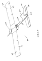
- FIG. 3 is a rear view of the UAV of FIG. 1 in accordance with an embodiment of the invention.
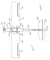
- FIG. 4 is a right side view of the UAV of FIG. 1 in accordance with an embodiment of the invention.
- FIG. 5 is a left side view of the UAV of FIG. 1 in accordance with an embodiment of the invention.
- FIG. 6 is a top view of the UAV of FIG. 1 in accordance with an embodiment of the invention.
- FIG. 7 is a bottom view of the UAV of FIG. 1 in accordance with an embodiment of the invention.
- FIG. 8 is a bottom perspective view of the UAV of FIG. 1 in accordance with an embodiment of the invention.
- FIG. 9 is a rear perspective view of the UAV of FIG. 1 in accordance with an embodiment of the invention.
- FIG. 10 is a cross sectional view of the UAV of FIG. 1 taken along line A-A in FIG. 6 in accordance with an embodiment of the invention
- FIG. 11 is an exploded view of the fuselage of the UAV of FIG. 1 in accordance with an embodiment of the invention.
- FIG. 12 is an enlarged side view of the fuselage of the UAV of FIG. 1 illustrating the payload bay in accordance with an embodiment of the invention
- FIG. 13 is a perspective view illustrating a threaded fastener for joining printed circuit boards in accordance with an embodiment of the invention
- FIG. 14 is a perspective view illustrating an angled solder pad board-to-board connection in accordance with an embodiment of the invention.
- FIG. 15 is a top view illustrating a slot and tab board-to-board connection in accordance with an embodiment of the invention.
- FIG. 16 is a block diagram illustrating a diagnostic circuit for monitoring airframe integrity in accordance with an embodiment of the invention.
- FIG. 17 is front perspective view illustrating an alternate unmanned aerial vehicle (“UAV”) in accordance with an embodiment of the invention.
- UAV unmanned aerial vehicle
- FIG. 18 is a front view of the UAV of FIG. 17 in accordance with an embodiment of the invention.
- FIG. 19 is a rear view of the UAV of FIG. 17 in accordance with an embodiment of the invention.
- FIG. 20 is a right side view of the UAV of FIG. 17 in accordance with an embodiment of the invention.
- FIG. 21 is a left side view of the UAV of FIG. 17 in accordance with an embodiment of the invention.
- FIG. 22 is a top view of the UAV of FIG. 17 in accordance with an embodiment of the invention.
- FIG. 23 is a bottom view of the UAV of FIG. 17 in accordance with an embodiment of the invention.
- FIG. 24 is a bottom perspective view of the UAV of FIG. 17 in accordance with an embodiment of the invention.
- FIG. 25 is a rear perspective view of the UAV of FIG. 17 in accordance with an embodiment of the invention.
- FIG. 26 is a break-away view of the fuselage of the UAV of FIG. 17 in accordance with an embodiment of the invention.
- FIG. 27 is front perspective view illustrating an alternate unmanned aerial vehicle (“UAV”) in accordance with an embodiment of the invention.
- UAV unmanned aerial vehicle
- FIG. 28 is a front view of the UAV of FIG. 27 in accordance with an embodiment of the invention.
- FIG. 29 is a rear view of the UAV of FIG. 27 in accordance with an embodiment of the invention.
- FIG. 30 is a right side view of the UAV of FIG. 27 in accordance with an embodiment of the invention.
- FIG. 31 is a left side view of the UAV of FIG. 27 in accordance with an embodiment of the invention.
- FIG. 32 is a top view of the UAV of FIG. 27 in accordance with an embodiment of the invention.
- FIG. 33 is a bottom view of the UAV of FIG. 27 in accordance with an embodiment of the invention.
- FIG. 34 is a bottom perspective view of the UAV of FIG. 27 in accordance with an embodiment of the invention.
- FIG. 35 is a rear perspective view of the UAV of FIG. 27 in accordance with an embodiment of the invention.
- FIG. 36 is a break-away view of the fuselage of the UAV of FIG. 27 in accordance with an embodiment of the invention.
- FIG. 37 is a block diagram illustrating a distributed control system for the UAV of FIG. 1 in accordance with an embodiment of the invention.
- an unmanned aerial vehicle (“UAV”) is provided that is constructed from printed circuit boards (“PCBs”).
- PCBs printed circuit boards
- the use of PCBs allows for a larger, improved capability, stronger, less expensive, yet complex UAV to be made.
- diagnostics and artificial intelligence may be included in the UAV without the need for extensive wiring.
- the use of PCB construction allows for sensors and circuits to be easily placed at the point of need by critical flight control systems and controls in the UAV.
- a PCB is used to mechanically support and electrically connect electronic components using conductive pathways, tracks, or traces etched from copper sheets laminated onto a non-conductive substrate.
- PCBs are used in most commercially produced electronic devices and allow for fully automated assembly processes. The majority of PCBs are made from laminate material with copper already applied to both sides. The unwanted copper is removed by various methods leaving only the desired conductive copper traces. This is a subtractive method. In an additive method, conductive traces are electroplated onto a bare substrate. Double-sided boards or multi-layer boards use plated-through holes, called vias, to connect traces on different layers of the PCB. After the PCB is completed, electronic components are attached to form a functional PCB assembly.
- component leads are inserted in holes in the PCB.
- components are placed on pads or lands on the outer surfaces of the PCB.
- component leads are electrically and mechanically connected to the board and its traces with a molten metal solder.
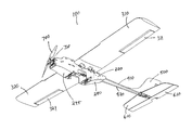
- FIG. 1 is front perspective view illustrating an unmanned aerial vehicle (“UAV”) 100 in accordance with an embodiment of the invention.
- UAV unmanned aerial vehicle
- FIG. 2 is a front view of the UAV 100 of FIG. 1 in accordance with an embodiment of the invention.
- FIG. 3 is a rear view of the UAV 100 of FIG. 1 in accordance with an embodiment of the invention.
- FIG. 4 is a right side view of the UAV 100 of FIG. 1 in accordance with an embodiment of the invention.
- FIG. 5 is a left side view of the UAV 100 of FIG. 1 in accordance with an embodiment of the invention.
- FIG. 6 is a top view of the UAV 100 of FIG. 1 in accordance with an embodiment of the invention.
- FIG. 7 is a bottom view of the UAV 100 of FIG.
- FIG. 8 is a bottom perspective view of the UAV 100 of FIG. 1 in accordance with an embodiment of the invention.
- FIG. 9 is a rear perspective view of the UAV 100 of FIG. 1 in accordance with an embodiment of the invention.
- FIG. 10 is a cross sectional view of the UAV 100 of FIG. 1 taken along line A-A in FIG. 6 in accordance with an embodiment of the invention.
- FIG. 11 is an exploded view of the fuselage 200 of the UAV 100 of FIG. 1 in accordance with an embodiment of the invention.
- FIG. 37 is a block diagram illustrating a distributed control system 3700 for the UAV 100 of FIG. 1 in accordance with an embodiment of the invention.
- the UAV 100 includes a fuselage 200 to which are mounted wings 310 , 320 and a tail boom 400 .
- a tail 450 including a vertical stabiliser 500 and a horizontal stabiliser 600 is mounted to the aft of the tail boom 400 .
- the UAV 100 is propelled by a drive propeller 700 mounted at the nose of the fuselage 200 .
- the UAV 100 includes a distributed control system 3700 for controlling and monitoring the UAV 100 .
- the fuselage 200 includes an elongate port side board 220 which forms the right sidewall of the fuselage 200 and an elongate starboard side board 230 which forms the left sidewall of the fuselage 200 .
- the fuselage 200 supports the mechanical structure or airframe of the UAV 100 and contains and protects payload modules and sensors removably mounted in a cargo or payload bay 201 .
- the fuselage 200 houses wiring, electronics, diagnostic components, batteries, sensors, and actuators required for operation of the UAV 100 .
- the drive propeller 700 may be a folding propeller to reduce blade breakage on landing.
- the drive motor 710 is coupled to the propeller 700 by a shaft.
- the motor 710 may be an electric motor which is powered by one or more batteries 3710 mounted in the fuselage 200 .
- the wings 310 , 320 may be formed from foam (e.g., StyrofoamTM, etc.) or other lightweight material.
- the wings 310 , 320 may be formed as a single wing or as two separate wings.
- the wings 310 , 320 includes respective ailerons 311 , 321 for controlling the roll of the UAV 100 .
- the wings 310 , 320 may also include respective flaps (not shown) for increasing lift and drag.
- the wings 310 , 320 may also include respective slats (not shown) for increasing lift.
- the wings 310 , 320 are the lifting airfoil of the UAV 100 .
- the wings 310 , 320 are positioned on the fuselage 200 such that the centre of gravity of the UAV 100 is near the centre of lift of the wings 310 , 320 to enhance stability.
- the vertical stabiliser 500 may be formed from foam (e.g., StyrofoamTM, etc.) or other lightweight material.
- the vertical stabiliser 500 is the UAV's vertical fin, functions as a yaw stabiliser, and supports the rudder 510 .
- the horizontal stabiliser 600 may be formed from foam (e.g., StyrofoamTM, etc.) or other lightweight material.
- the horizontal stabiliser 600 is the UAV's horizontal fin, functions as a pitch stabiliser, and supports the elevator 610 .
- the horizontal stabiliser 600 may include port and starboard elevators.
- the tail boom 400 may consist of separate port and starboard booms 410 , 420 mounted to the fuselage 200 by a tail mount 430 .
- the vertical stabiliser 500 and the horizontal stabiliser 600 may be mounted to the aft ends of the booms 410 , 420 by a tail cap 440 .
- the tail booms 410 , 420 may be formed from carbon fibre (or other lightweight material) and extend from the aft of the fuselage 200 to secure and support the vertical and horizontal stabilisers 500 , 600 and related actuator control lines.
- the tail mount 430 may be formed from plastic, prototyped, molded, or constructed. It supports the UAV's tail 450 via carbon fibre (or other lightweight material) tail booms 410 , 420 .
- the tail mount 430 also functions as a structural member spanning and joining the side boards 220 , 230 of the fuselage 200 .
- the tail cap 440 may be formed from plastic, prototyped, molded, or constructed. It joins the tail booms 410 , 420 and affixes the vertical and horizontal stabilisers 500 , 600 to the UAV 100 .
- the control system 3700 includes components (e.g., 1640 ) and sensors (e.g., 1650 ) which are distributed over the UAV's PCBs and airframe as described below.
- the control system 3700 includes a mission computer or processor 1640 , various sensors 1650 , a display 3740 , and an autopilot module 3750 .
- the fuselage 200 of the UAV 100 is constructed from PCBs (e.g., 220 , 230 ) and need not be covered by an external skin or shield. Rather, the PCBs (e.g., 220 , 230 ) provide both mechanical structure for the fuselage 200 of the UAV 200 and electrical connectivity between electrical components mounted thereon.
- PCBs e.g., 220 , 230
- the fuselage 200 includes a firewall plate or board 210 , a propeller 700 , a motor 710 , side boards 220 , 230 , a power board 297 , a GPS board 240 , a network board 250 , wing connect boards 261 , 262 , servo motors 271 , 272 , a tail mount 430 , a tail cover 280 , float struts 291 , 292 , 293 , 294 , a chin cover 295 , a top cover 299 , and a payload bay 201 .
- the fuselage 200 includes a firewall board 210 formed from PCB material.
- the firewall board 210 is typically formed from thicker, stronger, and heavier PCB material than that used for other fuselage components owing to the added strength needed to support the drive propeller 700 and motor 710 , which are mounted thereto, and to strengthen and secure the nose of the UAV 100 .
- the firewall board 210 functions as a structural member of the fuselage 200 , provides stiffness and strength to the fuselage 200 , and connects the side boards 220 , 230 of the fuselage 200 together. As mentioned, the firewall board 210 also secures the motor 710 to the fuselage 200 .
- the firewall board 210 has formed therein one or more vents 211 to permit cooling airflow through the fuselage 200 .
- the firewall board 210 may be attached to the port and starboard side boards 220 , 230 via four screw and threaded fasteners 212 which provide both mechanical and electrical connections.
- two threaded fasteners 212 mounted at the top and bottom of each side of the firewall board 210 are connected to the nose ends of each of the port and starboard side boards 220 , 230 via standard threaded screws which pass through clearance holes in the side boards 220 , 230 of the fuselage 200 .
- the four threaded screw and corresponding threaded fasteners 212 mounted on the firewall board 210 provide an electrical connection path for an electric voltage supply and communications circuitry to a thermal sensor (e.g., 1650 ) soldered on a PCB mounted immediately behind the motor 710 to sense the temperature of the motor 710 .
- a mission computer or processor 1640 may read this data relating to the status of the motor 710 for diagnostic and control purposes.
- the four threaded screws and corresponding threaded fasteners 212 provide the necessary strength to withstand impact of the nose of the UAV 100 with the ground upon landing.
- the electric drive motor 700 is used to drive or turn the propeller 700 .
- the motor 700 is driven by an electronic speed control (“ESC”) module 3730 and power system 3720 which are coupled to one or more batteries 3710 .
- the propeller 700 is used to provide thrust for the UAV 100 .
- the propeller 700 may have a folding configuration to avoid blade breakage on landing when the UAV 100 is landed on its belly.
- the batteries 3710 may be lithium polymer batteries, typically having at least a 3900 mAHr capacity.
- the port side board 220 is formed from PCB material.
- the port side board 220 may have mounted thereon components (e.g., 1650 ) and processors (e.g., 1640 ) for flight control, diagnostics, user interface, communications, and display electronics (e.g., 3740 ). It may also provide electrical and communications signals (e.g., via 1200 ) to a payload module (e.g., USB, USB on-the-go, Ethernet, PWM, IIC, digital lines, etc.) which may be mounted in the payload bay 201 .
- a payload module e.g., USB, USB on-the-go, Ethernet, PWM, IIC, digital lines, etc.
- the starboard side board 230 is formed from PCB material.
- the starboard side board 230 forms a sidewall of the fuselage 200 .
- the starboard side board 230 is both a structural component and an electronic component of the fuselage 200 .
- the starboard side board 230 may contain a variety of circuits and electronic components.
- the starboard side board 230 may support electrical connectivity to a starboard wing aileron servo motor 3760 (embedded in the starboard wing 320 ) and to a rudder servo motor 272 (mounted near the aft end of the fuselage 200 ).
- the starboard side board 230 may also contain diagnostic circuits (e.g., trace 1631 ) to sense damage and wear to the starboard side of the UAV 100 , temperature, and atmospheric pressure.
- the starboard side board 230 may also contain power supply components (e.g., power bus 3770 ) which provide necessary voltage supplies to the various components of the UAV 200 and to the payload module optionally mounted in the payload bay 201 .
- the port and starboard side boards 220 , 230 may include an internal copper plane to enhance shielding and reduce radio frequency (“RF”) noise affecting or emanating from electrical and electronic components in the UAV 100 .
- RF radio frequency
- the power board 297 is formed from PCB material.
- the power board 297 is mounted horizontally behind the firewall board 210 between the port and starboard side boards 220 , 230 .
- the power board 297 functions as both a structural component and an electrical component of the fuselage 200 .
- the power board 297 may be tapered toward the nose of the UAV 100 thus tapering the side boards 220 , 230 .
- the power board 297 functions as an electronics bus between the port and starboard side boards 220 , 230 . It may also house an electronic speed control module 3730 which generates power lines for the servo motors (e.g., 271 , 272 ).
- the power board 297 is the main connection point for flight batteries 3710 which are mounted thereto and for corresponding power circuitry (i.e., power transmission traces to the electronic speed control module 3730 and lighter traces to the voltage supplies which then power the voltage or power bus 3770 ).
- the power board 297 may use battery switching technology to be able to draw power from alternate or optional batteries 3710 independently.
- an optional battery may be mounted in the fuselage 200 above the tail cover 280 aft of the payload bay 201 .
- the power board 297 may include connection points for a radio modem and a radio which may be mounted thereto.
- the geographical positioning system (“GPS”) board 240 is formed from PCB material.
- the GPS board 240 is mounted horizontally above the power board 297 between the port and starboard side boards 220 , 230 .
- the GPS board 240 functions as both a structural component and an electrical component of the fuselage 200 .
- the GPS board 240 provides structural support to the fuselage 200 by increasing stiffness and strength. It also serves to shield a static air pressure sensor mounted internal to the fuselage 200 from direct sunlight which helps to avoid erroneous altimeter readings.
- the GPS board 240 may be used to align the various components of the fuselage 200 and UAV 100 .
- the GPS board 240 contains or has mounted thereon a GPS receiver module 3780 , a GPS antenna, pulse-per-second indicators, communications circuitry, and supporting components.
- the GPS board 240 may also contain a copper plane for improving performance of the GPS antenna.
- the network board 250 is formed from PCB material.
- the network board 250 is mounted horizontally aft of the GPS board 240 and above the payload bay 201 between the port and starboard side boards 220 , 230 .
- the network board 250 functions as both a structural component and an electrical component of the fuselage 200 .
- the network board 240 provides structural support to the UAV 100 to increase stiffness and strength.
- the network board 250 contains circuitry to support two separate computer-on-module units and Ethernet networking components. The Ethernet networking components may facilitate communications between the two computer modules.
- the Ethernet networking components may also include a 10 Mbps Ethernet switch 3790 to communicate between the computer modules and a main mission control computer or processor 1640 located on the port side board 220 , two separate Ethernet lines to the payload bay 201 , and an Ethernet line to a RJ-45 jack located on the starboard side board 230 .
- the two wing connect boards 261 , 262 are formed from PCB material.
- the wing connect boards 261 , 262 are mounted horizontally above and at each of the fore and aft ends of the network board 250 between the port and starboard side boards 220 , 230 .
- the wing connect boards 261 , 262 function as both structural components and electrical components of the fuselage 200 .
- the wing connect boards 261 , 262 are used to: provide electrically connectivity between the sensors 1650 and actuators/servos 3760 in the wings 310 , 320 and the rest of the UAV 100 ; provide a means to attach the wings 310 , 320 (which may be removed from the UAV 100 for transport) together and to the fuselage 200 ; and, provide torsional stiffness to the wings 310 , 320 at the joint between them.
- the wing connect boards 261 , 262 are symmetric and may be interchanged with each other until installed on the wings 310 , 320 at which point the boards 261 , 262 , connectors, and wings 310 , 320 may become polarised such that they may only be installed in one, correct, configuration.
- the servo motors 271 , 272 are driven by electronics mounted on the side boards 220 , 230 and are used to actuate the flight control surfaces (e.g., 510 , 610 ) of the UAV 100 .
- the starboard servo motor 272 is mounted on the inner side of the starboard side board 230 aft of the network board 250 and drives the rudder 510 via a pushrod system installed along the tail booms 410 , 420 .
- the port servo motor 271 is mounted on the inner side of the port side board 220 aft of the network board 250 and drives the elevator 610 via a pushrod system installed along the tail booms 410 , 420 .
- servo motors e.g., 3760
- embedded in the wings 310 , 320 drive the ailerons 311 , 321 directly via metal linkages.
- the tail mount 420 is mounted horizontally aft of the servo motors 271 , 272 between the side boards 220 , 230 of the fuselage 200 .
- the tail mount 430 may be formed from plastic, prototyped, molded, or constructed.
- the tail mount 430 supports the UAV's tail 450 via carbon fibre (or other lightweight material) tail booms 410 , 420 .
- the tail mount 430 also functions as a structural member spanning and joining the side boards 220 , 230 of the fuselage 200 .
- the tail mount 430 may be used to tapper the aft ends of the side boards 220 , 230 to improve aerodynamic performance of the UAV 100 .
- the tail cover 280 is formed from PCB material.
- the tail cover 280 is mounted horizontally under the tail mount 430 between the port and starboard side boards 220 , 230 .
- the tail cover 280 is a thin, flexible board used to provide protection for the internal components of the UAV 100 from dust and dirt and to provide improved aerodynamic performance by providing a smoother transition to the tail booms 410 , 420 following the tapering of the side boards 220 , 230 at their aft ends.
- the tail cover 280 has no electrical function. However, it some embodiments, an optional battery may be mounted thereon.
- the four float struts 291 , 292 , 293 , 294 are formed from PCB material.
- the float struts 291 , 292 , 293 , 294 are mounted horizontally in vertical pairs (e.g., 292 / 291 and 294 / 293 ) on each of the fore and aft sides of the payload bay 201 between the bottom edges of the port and starboard side boards 220 , 230 .
- the float struts 291 , 292 , 293 , 294 function as structural components to increase strength and rigidity of the fuselage 200 .
- they are used as hard mount points when the UAV 100 is operated with amphibious floats, wheels, or other external accessories. In general, the UAV 100 is not equipped with landing gear when used over land.
- the chin cover 295 is formed from PCB material.
- the chin cover 295 is mounted horizontally under the power board 297 aft of the firewall board 210 between the lower edges of the port and starboard side boards 220 , 230 .
- the chin cover 295 is a thin, flexible board used to provide protection for the internal components of the UAV 100 from dust and dirt and to provide better aerodynamic performance by providing a smoother transition from the firewall board 210 to the first set of float struts 291 , 292 fore of the payload bay 201 following the tapering of the side boards 220 , 230 at their fore ends.
- the chin cover 295 also provides structural stiffness to the a battery holder to which it may be attached. In general, it has no electrical function.
- the top cover 299 is formed from PCB material.
- the top 299 is mounted horizontally over the power board 297 and the GPS board 240 aft of the firewall board 210 between the upper edges of the port and starboard side boards 220 , 230 .
- the top cover 299 is a thin, flexible board used to provide protection for the internal components of the UAV 100 from dust and dirt and to provide better aerodynamic performance by providing a smoother transition from the firewall board 210 to the wings 310 , 320 following the tapering of the side boards 220 , 230 at their fore ends. In general, it has no electrical function.
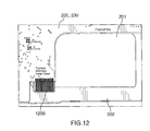
- FIG. 12 is an enlarged side view of the fuselage 200 of the UAV 100 of FIG. 1 illustrating the payload bay 201 in accordance with an embodiment of the invention.
- the payload bay 201 is positioned on the bottom of the fuselage 200 and is for receiving variously configured payload modules.
- a camera module may be loaded into the payload bay 201 for scanning a farmer's field.
- the payload module may be coupled to various electronic components onboard the UAV 100 using an edge connector which may be received by a payload interface 1200 etched into a side board 220 , 230 of the fuselage 200 as shown in FIG. 12 .
- FIG. 12 is one example of how PCBs may be used to directly provide removable electrical connections by using shape and conductor placement to mate with other components.
- the payload bay 201 may be covered by an optional payload bay cover 202 .
- the fuselage 200 of the UAV 100 is constructed using PCBs with integral electronic circuits in addition to foam, plastic, and carbon fibre used for the wings 310 , 320 and tail 450 , tail mount 430 , tail cap 440 , and tail boom 400 .
- the fuselage 200 of the UAV 100 is constructed using PCBs arranged in a three-dimensional, box-like configuration and connected to one another using one or more different types of connections.
- some of the PCBs may or may not contain active or passive electric circuits and some may or may not serve to provide mechanical structure.
- the UAV's fuselage 200 functions as the UAV's circuitry, computer, and diagnostic platform. It enables the use of embedded “sensor-as-structure” construction which allows sensors to be placed in areas of key mechanical need. For example, pressure sensors which are sensitive to direct sunlight may be placed under the wings 310 , 320 inside the fuselage 200 to protect them from sunlight. Accelerometers used to measure aircraft pose and which are critical for stabilisation may be ideally placed at the centre of gravity of the UAV 100 . In addition, temperature sensors may be placed at locations of need such as at the motor 710 , speed controllers, and throughout the UAV 100 . All of this may be accomplished without the need for complicated, bulky, heavy, and hard to manufacture wiring harnesses.
- connection may be referred to as a board-to-board connection.
- Board-to-board connections may serve to provide electrical connectivity, mechanical connectivity, or both.
- board-to-board connections may take the form of one or more of the following types: screw and threaded fastener; angled solder pad; and, slot and tab.
- FIG. 13 is a perspective view illustrating a threaded fastener 212 for joining PCBs in accordance with an embodiment of the invention. Connections may be achieved using components that are soldered to one PCB and attached to another PCB via a threaded fastener 212 . In particular, PCBs may be connected to other components (such as wings 310 , 320 , tail 450 , etc.) using standard threaded fasteners 212 . As described above, this is how the firewall board 210 may be connected to the side boards 220 , 230 .
- the threaded fastener 212 is soldered to a first PCB (e.g., firewall board 210 ) and a screw is passed through an opening formed in a second PCB (e.g., side board 220 ) and is received by the threaded fastener 212 .
- a first PCB e.g., firewall board 210
- a screw is passed through an opening formed in a second PCB (e.g., side board 220 ) and is received by the threaded fastener 212 .
- FIG. 14 is a perspective view illustrating an angled solder pad board-to-board connection 1400 in accordance with an embodiment of the invention.
- Board-to-board connections may be implemented using angled solder points or pads 1400 which are then joined using a bead of solder. This method of connection may be combined with the slot and tab method described below.
- FIG. 15 is a top view illustrating a slot and tab board-to-board connection 1500 in accordance with an embodiment of the invention.
- Board-to-board connections may be implemented by inserting fitted tabs 1510 on a first PCB (e.g., network board 250 ) into corresponding slots 1520 on a second PCB (e.g., side board 220 ) to which a bead of solder is then applied as a mechanical adhesive and/or to complete an electrical connection.
- a first PCB e.g., network board 250
- a second PCB e.g., side board 220
- FIG. 16 is a block diagram illustrating a diagnostic circuit 1600 for monitoring airframe (i.e., fuselage 200 , wings 310 , 320 , boom 400 , tail 450 ) integrity in accordance with an embodiment of the invention.
- the circuits (e.g., 1600 ) formed on the various PCBs (e.g., 230 ) of the UAV 100 may serve a variety of functions including diagnostics, computation, and communications (which may include board-to-board, board-to-component, or device-to-device communications).
- Diagnostic circuits 1600 may include sensors which may be implemented in passive sensor-as-structure form using only copper traces (e.g., 1631 ).
- Sensors may also be discrete devices (e.g., 1650 ) used to measure performance or status of key aircraft and flight control components and parameters. Sensors 1650 may also be implemented by other means using the circuit carrying capacity of the UAV's PCBs.
- the diagnostic circuit 1600 includes a matrix of rows 1610 and columns 1620 of connected conductive traces 1630 that are monitored by a processor 1640 to detect cracks and other problems relating to the UAV's airframe.
- a trace 1631 may be etched into and routed around the perimeter of the side boards 220 , 230 of the fuselage 200 .
- a trace 1631 would be broken or damaged and this break or damage may be detected by the processor 1640 and reported to the user (e.g., via display 3740 ).
- a trace may be used to monitor the connection of a flight control servo motor 271 to a side board 220 via encircling the mounting hole(s) for the servo motor 271 in the side board 220 .
- a trace may be used motor a board-to-board connection by encircling the mounting hole(s) for a thread connector 212 in the firewall board 210 .
- the fuselage 200 of the UAV 100 may also be used as a standalone computational, electrical, and sensing platform.
- the fuselage 200 may be mounted on a conventional aircraft as a platform for performing various functions.
- the memory of the processor 1640 of the UAV 100 may be loaded with a flight plan relating to scanning a farmer's field for crop growth information.
- a camera module may be loaded into the payload bay 201 to perform the scanning.
- the motor 710 of the UAV 100 may be started remotely and the UAV 100 may be hand or ground launched.
- Data received from the camera module may be stored in memory on board the module or on board the UAV 100 or the data may be transmitted to an external system from the UAV 100 .
- the UAV 100 may be instructed to land by a user on the ground employing a remote control unit.
- FIG. 17 is front perspective view illustrating an alternate unmanned aerial vehicle (“UAV”) 1000 in accordance with an embodiment of the invention.
- UAV unmanned aerial vehicle
- FIG. 18 is a front view of the UAV 1000 of FIG. 17 in accordance with an embodiment of the invention.
- FIG. 19 is a rear view of the UAV 1000 of FIG. 17 in accordance with an embodiment of the invention.
- FIG. 20 is a right side view of the UAV 1000 of FIG. 17 in accordance with an embodiment of the invention.
- FIG. 21 is a left side view of the UAV 1000 of FIG. 17 in accordance with an embodiment of the invention.
- FIG. 22 is a top view of the UAV 1000 of FIG. 17 in accordance with an embodiment of the invention.
- FIG. 23 is a bottom view of the UAV 1000 of FIG.
- FIG. 24 is a bottom perspective view of the UAV 1000 of FIG. 17 in accordance with an embodiment of the invention.
- FIG. 25 is a rear perspective view of the UAV 1000 of FIG. 17 in accordance with an embodiment of the invention.
- FIG. 26 is a break-away view of the fuselage 200 of the UAV 1000 of FIG. 17 in accordance with an embodiment of the invention.
- the alternate UAV 1000 shown therein has a single wing 300 and tail 450 which are designed to resemble those of a bird such as a hawk.
- the tail 450 may be connected directly to the fuselage 200 .
- the fuselage 200 has a simplified construction and may carry a payload module internally.
- FIG. 27 is front perspective view illustrating an alternate unmanned aerial vehicle (“UAV”) 2000 in accordance with an embodiment of the invention.
- UAV unmanned aerial vehicle
- FIG. 28 is a front view of the UAV 2000 of FIG. 27 in accordance with an embodiment of the invention.
- FIG. 29 is a rear view of the UAV 2000 of FIG. 27 in accordance with an embodiment of the invention.
- FIG. 30 is a right side view of the UAV 2000 of FIG. 27 in accordance with an embodiment of the invention.
- FIG. 31 is a left side view of the UAV 2000 of FIG. 27 in accordance with an embodiment of the invention.
- FIG. 32 is a top view of the UAV 2000 of FIG. 27 in accordance with an embodiment of the invention.
- FIG. 33 is a bottom view of the UAV 2000 of FIG.
- FIG. 34 is a bottom perspective view of the UAV 2000 of FIG. 27 in accordance with an embodiment of the invention.
- FIG. 35 is a rear perspective view of the UAV 2000 of FIG. 27 in accordance with an embodiment of the invention.
- FIG. 36 is a break-away view of the fuselage 200 of the UAV 2000 of FIG. 27 in accordance with an embodiment of the invention.
- the alternate UAV 2000 shown therein has two wings 310 , 320 and tail 450 similar to that of the embodiment of FIGS. 1-11 .
- the fuselage 200 has a simplified construction similar to that of the embodiment of FIGS. 17-26 .
- the single hawk-like wing 300 and/or tail 450 of the UAV 1000 of FIGS. 17-26 may also be used on the UAV 100 of FIGS. 1-11 and/or the UAV 2000 of FIGS. 27-36 .
- the wings 310 , 320 and/or tail 450 of the UAVs 100 , 2000 of FIGS. 1-11 and/or FIGS. 27-36 may also be used on the UAV 1000 of FIGS. 17-26 .
- an unmanned aerial vehicle (“UAV”) 100 comprising: a fuselage 200 having a first side board 220 and a second side board 230 spaced apart and connected by at least one transverse board (e.g., 297 ); the first side board 220 , the second side board 230 , and the at least one transverse board 297 being printed circuit boards; at least one of the first side board 220 , the second side board 230 , and the at least one transverse board 297 having formed and mounted thereon conductive traces 1630 and at least one component (e.g., 1640 ), respectively, for controlling and monitoring the unmanned aerial vehicle 100 ; first and second wings 310 , 320 mounted to the fuselage 200 ; and, a tail 450 mounted to the fuselage 200 .
- UAV unmanned aerial vehicle
- the above UAV 100 may further include a conductive trace 1631 routed proximate a perimeter of at least one of the first side board 220 and the second side board 230 for detecting damage to the at least one of the first side board 220 and the second side board 230 .
- the UAV 100 may further include a conductive trace routed proximate a connection 1400 between the at least one transverse board 297 and at least one of the first side board 220 and the second side board 230 for detecting damage to the connection 1400 .
- the UAV 100 may further include a conductive trace routed proximate a connection between the at least one component 1640 and at least one of the first side board 220 , the second side board 230 , and the at least one transverse board 297 for detecting damage to at least one of the connection and the at least one component 1640 .
- the UAV 100 may further include a propeller 700 and motor 710 for providing thrust.
- the motor 710 may be an electric motor.
- the UAV 100 may further include a battery 3710 mounted in the fuselage 200 for providing electric power to the electric motor 710 and to the at least one component 1640 .
- the first side board 220 and the second side board 230 may be vertical and parallel and the at least one transverse board 297 may be horizontal.
- the at least one component may include a processor 1640 .
- the UAV 100 may further include a payload bay 201 formed proximate bottom edges of the first side board 220 and the second side board 230 , the payload bay 201 for mounting a payload module. At least one of the first side board 220 and the second side board 230 may be provided with at least one conductive trace 1200 for receiving an electrical connector of the payload module.
- the payload module may be a camera.
- the wings 310 , 320 may be detachable.
- the at least one component may include at least one sensor 1650 .
- the UAV 100 may further include at least one boom 400 for mounting the tail 450 to the fuselage 200 .
- the tail 450 may include a horizontal stabiliser 600 and a vertical stabiliser 500 .
- the at least one component may include at least one servo motor 271 , 272 for adjusting flight control surfaces 610 , 510 of the horizontal stabiliser 600 and the vertical stabiliser 500 .
- the UAV 100 may further include at least one opening 211 formed in a nose (e.g., 210 ) of the fuselage 200 to allow air to pass therethrough to cool the at least one component 1640 .
- the first side board 220 and the second side board 230 may be elongate and may be tapered toward fore and aft of the fuselage 200 .
- the above embodiments may contribute to an improved unmanned aerial vehicle (“UAV”) 100 and may provide one or more advantages.
- the UAV 100 reduces or eliminates the need for trained unmanned aircraft operators on the ground and allows civilian users (e.g., farmers, etc.) to collect high quality remote sensing data.
- the UAV 100 is easy to use having intelligent systems and generating flight planning, diagnostics, and flight control information on board.
- the UAV 100 has an improved diagnostic and control system 3700 which is used to sense damage and fatigue, respond to unsafe wind and weather conditions, and recognise incompatible commands from a user.
- the diagnostic and control system 3700 may include temperature and mechanical sensing of the airframe itself as well as critical components such as the motor, speed control devices, etc.
- the ability to recognise failures at key structural areas allows the UAV 100 to land and/or prevent flight prior to catastrophic failure of a component of the UAV 100 or the UAV 100 itself.
- the UAV 100 may be made at reduced cost, is robust with improved reliability, and is scalable from a manufacturing perspective.
- improved computational resources and redundant systems may also be included within a small footprint on board the UAV 100 and with as little additional weight as possible.
- the use of PCB circuit-as-structure construction allows for: mechanical sensing embodied in the airframe itself; reduction in wiring for lighter weight; and, enables the placement of electronics, computers, and sensors anywhere in the UAV 100 to support required functions and capabilities.
- PCB materials are very rugged, robust, and allow for rapid and readily available manufacturing at large scale.
- the structure of the UAV 100 allows for complex electronic capabilities including sensor, power distribution, and computation to be readily placed at the point of need in the UAV 100 , implemented with minimal weight, and without the need for large, bulky, heavy and expensive wiring harnesses.
- the UAV 100 is strong, rigid, and light weight.
- the UAV 100 is inexpensive and fast to make by using well established manufacturing technologies that allow for production to be easily and rapidly scaled.
- the PCB-based structure allows for a light, strong, inexpensive, yet very complex UAV 100 to be rapidly manufactured and deployed.
Landscapes
- Engineering & Computer Science (AREA)
- Aviation & Aerospace Engineering (AREA)
- Microelectronics & Electronic Packaging (AREA)
- Mechanical Engineering (AREA)
- Remote Sensing (AREA)
- Toys (AREA)
Abstract
Description
Claims (21)
Priority Applications (1)
| Application Number | Priority Date | Filing Date | Title |
|---|---|---|---|
| US13/892,358 US8991758B2 (en) | 2013-05-13 | 2013-05-13 | Unmanned aerial vehicle |
Applications Claiming Priority (1)
| Application Number | Priority Date | Filing Date | Title |
|---|---|---|---|
| US13/892,358 US8991758B2 (en) | 2013-05-13 | 2013-05-13 | Unmanned aerial vehicle |
Publications (2)
| Publication Number | Publication Date |
|---|---|
| US20140332620A1 US20140332620A1 (en) | 2014-11-13 |
| US8991758B2 true US8991758B2 (en) | 2015-03-31 |
Family
ID=51864109
Family Applications (1)
| Application Number | Title | Priority Date | Filing Date |
|---|---|---|---|
| US13/892,358 Active 2033-07-13 US8991758B2 (en) | 2013-05-13 | 2013-05-13 | Unmanned aerial vehicle |
Country Status (1)
| Country | Link |
|---|---|
| US (1) | US8991758B2 (en) |
Cited By (14)
| Publication number | Priority date | Publication date | Assignee | Title |
|---|---|---|---|---|
| USD800843S1 (en) * | 2016-09-01 | 2017-10-24 | Unmanned Innovation Inc. | Airframe |
| US9945828B1 (en) | 2015-10-23 | 2018-04-17 | Sentek Systems Llc | Airborne multispectral imaging system with integrated navigation sensors and automatic image stitching |
| US10032078B2 (en) | 2014-01-10 | 2018-07-24 | Pictometry International Corp. | Unmanned aircraft structure evaluation system and method |
| USD825381S1 (en) | 2017-07-13 | 2018-08-14 | Fat Shark Technology SEZC | Unmanned aerial vehicle |
| CN108883829A (en) * | 2016-04-14 | 2018-11-23 | 高通股份有限公司 | Electronic speed controller arm for unmanned vehicle |
| US10179647B1 (en) | 2017-07-13 | 2019-01-15 | Fat Shark Technology SEZC | Unmanned aerial vehicle |
| US20190135403A1 (en) * | 2017-08-01 | 2019-05-09 | Zipline International Inc. | Unmanned aircraft system with swappable components |
| USD848383S1 (en) | 2017-07-13 | 2019-05-14 | Fat Shark Technology SEZC | Printed circuit board |
| US10618627B2 (en) * | 2018-02-13 | 2020-04-14 | Bell Helicopter Textron Inc. | Rudder twist lock method and apparatus |
| US11091262B2 (en) * | 2015-06-01 | 2021-08-17 | SZ DJI Technology Co., Ltd. | Systems and methods for foldable arms |
| US11352136B2 (en) * | 2017-11-20 | 2022-06-07 | Airbus Defence And Space Sas | Structure of payload module for stratospheric drone |
| US12079013B2 (en) | 2016-01-08 | 2024-09-03 | Pictometry International Corp. | Systems and methods for taking, processing, retrieving, and displaying images from unmanned aerial vehicles |
| USD1075566S1 (en) * | 2023-05-05 | 2025-05-20 | WingXpand, Inc. | Expandable wing aircraft |
| US12332660B2 (en) | 2018-11-21 | 2025-06-17 | Eagle View Technologies, Inc. | Navigating unmanned aircraft using pitch |
Families Citing this family (41)
| Publication number | Priority date | Publication date | Assignee | Title |
|---|---|---|---|---|
| US11292622B2 (en) * | 2013-10-07 | 2022-04-05 | Shay C. Colson | 3D printed vehicle packaging |
| US12462415B2 (en) * | 2014-05-06 | 2025-11-04 | Okkola Technologies, Llc | Stationary aerial platform scanning system utilizing measured distances for the construction, displaying terrain features and location of objects |
| US9087451B1 (en) | 2014-07-14 | 2015-07-21 | John A. Jarrell | Unmanned aerial vehicle communication, monitoring, and traffic management |
| US9596020B2 (en) | 2014-08-18 | 2017-03-14 | Sunlight Photonics Inc. | Methods for providing distributed airborne wireless communications |
| US11968022B2 (en) | 2014-08-18 | 2024-04-23 | Sunlight Aerospace Inc. | Distributed airborne wireless communication services |
| US9083425B1 (en) | 2014-08-18 | 2015-07-14 | Sunlight Photonics Inc. | Distributed airborne wireless networks |
| US9302782B2 (en) * | 2014-08-18 | 2016-04-05 | Sunlight Photonics Inc. | Methods and apparatus for a distributed airborne wireless communications fleet |
| US9550400B2 (en) | 2014-10-29 | 2017-01-24 | Qualcomm Incorporated | Unmanned aerial vehicle |
| US9688400B2 (en) * | 2014-10-29 | 2017-06-27 | Qualcomm Incorporated | Unmanned aerial vehicle |
| US9630710B2 (en) | 2014-10-29 | 2017-04-25 | Qualcomm Incorporated | Unmanned aerial vehicle |
| CN104535048B (en) * | 2014-12-23 | 2015-11-11 | 河南四维远见信息技术有限公司 | A kind of unmanned vehicle remote sensing system and unmanned vehicle remote sensing technique |
| US9540121B2 (en) * | 2015-02-25 | 2017-01-10 | Cisco Technology, Inc. | Pre-flight self test for unmanned aerial vehicles (UAVs) |
| CN104691736A (en) * | 2015-03-12 | 2015-06-10 | 江苏艾锐泰克无人飞行器科技有限公司 | Fixed-wing unmanned aerial vehicle |
| WO2016149614A1 (en) * | 2015-03-19 | 2016-09-22 | Aerovironment, Inc. | Mounting system for mechanical-shock resistant printed circuit board (pcb) |
| GB2540792A (en) * | 2015-07-28 | 2017-02-01 | Airbus Operations Ltd | Vehicle fairing including an electrical routing |
| US10155373B2 (en) * | 2015-10-16 | 2018-12-18 | Quest Integrated, Llc | Printed multifunctional skin for aerodynamic structures, and associated systems and methods |
| CN105314085B (en) * | 2015-10-30 | 2018-11-20 | 易瓦特科技股份公司 | Hand throws unmanned plane |
| USD859280S1 (en) * | 2015-12-18 | 2019-09-10 | Leonardo S.P.A. | Combined aircraft and scale model |
| USD858420S1 (en) * | 2015-12-18 | 2019-09-03 | Leonardo S.P.A. | Combined airplane and scale model |
| CN107223108B (en) * | 2016-02-29 | 2019-09-27 | 深圳市大疆创新科技有限公司 | Power components, unmanned aerial vehicles and remote control mobile devices |
| USD810621S1 (en) * | 2016-04-12 | 2018-02-20 | King Saud University | Aerial vehicle |
| US10529221B2 (en) | 2016-04-19 | 2020-01-07 | Navio International, Inc. | Modular approach for smart and customizable security solutions and other applications for a smart city |
| CN106227234B (en) * | 2016-09-05 | 2019-09-17 | 天津远度科技有限公司 | Unmanned plane, unmanned plane take off control method and device |
| CN106741891B (en) * | 2016-11-30 | 2023-06-16 | 厦门汉航精密科技有限公司 | Unmanned aerial vehicle structure |
| US10340820B2 (en) * | 2016-12-30 | 2019-07-02 | Wing Aviation Llc | Electrical system for unmanned aerial vehicles |
| CN106896823B (en) * | 2017-04-28 | 2018-09-21 | 上海拓攻机器人有限公司 | The control device and unmanned vehicle of unmanned vehicle |
| CN110506003B (en) * | 2017-05-08 | 2024-01-05 | 英西图公司 | Modular aircraft with vertical takeoff and landing capability and method of operating the same |
| US10705187B1 (en) * | 2017-05-18 | 2020-07-07 | United States Of America, As Represented By The Secretary Of The Navy | Aerial drone for radar calibration |
| EP3446974B1 (en) * | 2017-08-23 | 2024-11-06 | Unusual Machines, Inc. | Unmanned aerial vehicle |
| US10940932B2 (en) * | 2017-10-11 | 2021-03-09 | Wing Aviation Llc | Modular fuselage for unmanned aerial vehicle |
| CN108287000B (en) * | 2018-01-25 | 2020-08-07 | 数字鹰电子(湖北)有限公司 | Environmental monitoring drone |
| EP3784570B1 (en) * | 2018-04-27 | 2022-10-26 | Textron Systems Corporation | Variable pitch rotor assembly for electrically driven vectored thrust aircraft applications |
| CN108688827A (en) * | 2018-08-22 | 2018-10-23 | 东汉太阳能无人机技术有限公司 | a drone |
| CN109229368B (en) * | 2018-08-31 | 2023-09-19 | 中国科学院光电研究院 | Concealed autonomous flight micro unmanned aerial vehicle |
| US11477888B2 (en) * | 2018-10-08 | 2022-10-18 | Quest Integrated, Llc | Printed multifunctional skin for aerodynamic structures and associated systems and methods |
| JP6765556B1 (en) * | 2018-12-21 | 2020-10-07 | 楽天株式会社 | Flight equipment, flight systems and information processing equipment |
| US11370555B2 (en) * | 2019-12-27 | 2022-06-28 | Wing Aviation Llc | Systems and methods for stopping movement of operational members |
| USD969671S1 (en) * | 2020-10-04 | 2022-11-15 | Matteo Trapani | Delivery drone |
| US11679875B2 (en) * | 2020-12-03 | 2023-06-20 | Saudi Arabian Oil Company | Mechanism for docking a magnetic crawler into a UAV |
| US11753137B2 (en) * | 2021-08-31 | 2023-09-12 | Textron Systems Corporation | Utilizing a customizable fuselage assembly for an unmanned aerial vehicle |
| CN113682469B (en) * | 2021-09-30 | 2023-03-10 | 北京航空航天大学 | Overall layout of small long-endurance unmanned aerial vehicle |
Citations (40)
| Publication number | Priority date | Publication date | Assignee | Title |
|---|---|---|---|---|
| US743301A (en) | 1903-07-30 | 1903-11-03 | Joseph F Heurteur | Kite. |
| US1507192A (en) | 1924-03-11 | 1924-09-02 | Laukandt Bernhard Frank | Toy airplane |
| US2762590A (en) | 1954-06-17 | 1956-09-11 | Kenneth K Huie | Kite |
| US3787998A (en) | 1973-01-16 | 1974-01-29 | Mattel Inc | Gliding toy |
| US3839818A (en) | 1973-10-18 | 1974-10-08 | E Heggedal | Glider with automatically releasing foldable wings |
| US4863413A (en) | 1988-04-11 | 1989-09-05 | Schwarz Charles F | Bird shaped toy glider |
| US4911384A (en) | 1989-03-28 | 1990-03-27 | Stankus Marguerite E | Winged kite |
| US5150860A (en) | 1991-04-23 | 1992-09-29 | The Boeing Company | Air vehicle launching device |
| US5524851A (en) | 1995-03-20 | 1996-06-11 | Huang; Ching-Chen | Kite assembly |
| US5609312A (en) * | 1991-09-30 | 1997-03-11 | Arlton; Paul E. | Model helicopter |
| US6095458A (en) | 1998-12-04 | 2000-08-01 | Cripe; James A. | Dynamic winged animal device |
| US20020173217A1 (en) | 2001-05-17 | 2002-11-21 | Kinkade Andrew Sean | Ornithopter |
| US6520823B2 (en) | 2000-07-14 | 2003-02-18 | Shanghai Helang Electronics Co., Ltd. | Remote electro-aeroplane |
| US6615165B2 (en) | 2001-09-27 | 2003-09-02 | Ernest A. Carroll | Cable connections between an unmanned aircraft and a detachable data handling module |
| US20040007646A1 (en) | 2002-07-12 | 2004-01-15 | Chin-Chuan Chang | Kite |
| US6742741B1 (en) | 2003-02-24 | 2004-06-01 | The Boeing Company | Unmanned air vehicle and method of flying an unmanned air vehicle |
| USD495376S1 (en) | 2003-12-24 | 2004-08-31 | Franklin Zee | Toy airplane |
| US6868314B1 (en) * | 2001-06-27 | 2005-03-15 | Bentley D. Frink | Unmanned aerial vehicle apparatus, system and method for retrieving data |
| US7059566B2 (en) * | 2003-06-20 | 2006-06-13 | The United States Of America As Represented By The Secretary Of The Navy | Unmanned aerial vehicle for logistical delivery |
| US7073748B2 (en) * | 2004-07-15 | 2006-07-11 | Lockheed Martin Corporation | UAV comprising a sensing system for detection and identification of biological particles |
| US20060255209A1 (en) | 2005-05-16 | 2006-11-16 | Chien-Chao Chen | Toy helicopter landing skid structure |
| US7237750B2 (en) | 2004-10-29 | 2007-07-03 | L3 Communications | Autonomous, back-packable computer-controlled breakaway unmanned aerial vehicle (UAV) |
| US20080125920A1 (en) * | 2004-10-08 | 2008-05-29 | Fugro Aiirborne Surveys Corporation | Unmanned Airborne Vehicle For Geophysical Surveying |
| US7391622B2 (en) * | 2004-05-19 | 2008-06-24 | The Boeing Company | Composite structural member having an integrated electrical circuit |
| US20080149758A1 (en) | 2006-04-21 | 2008-06-26 | Colgren Richard D | Modular unmanned air-vehicle |
| USD581992S1 (en) | 2006-12-19 | 2008-12-02 | Wang Jung-Yuan Jay | Toy glider |
| USD585370S1 (en) | 2008-02-25 | 2009-01-27 | Ta-Sen Tu | Fuselage frame |
| USD596267S1 (en) * | 2006-04-21 | 2009-07-14 | Colgren Richard D | Modular unmanned air-vehicle |
| USD608268S1 (en) | 2007-10-17 | 2010-01-19 | Bird Raptor Internacional SL | Airplane |
| US20100120273A1 (en) * | 2008-11-13 | 2010-05-13 | Honeywell International Inc. | Structural ring interconnect printed circuit board assembly for a ducted fan unmanned aerial vehicle |
| USD621774S1 (en) | 2008-07-25 | 2010-08-17 | Matthias Betsch | Airplane |
| US7811151B2 (en) | 2005-05-05 | 2010-10-12 | Elliot Rudell | Toy airplane with foldable wings and a switch to activate a plane propeller |
| USD628528S1 (en) | 2009-01-16 | 2010-12-07 | Instituto Nacional de Tecnica Aeroespacial ‘Esteban Terradas’ | Aeroplane |
| US20100323579A1 (en) | 2007-09-28 | 2010-12-23 | Shenzhen Art-Tech R/C Hobby Co., Ltd. | Four-channel transverse dual rotor helicopter |
| USD656999S1 (en) | 2009-12-01 | 2012-04-03 | David Frederick | Helicopter fuselage frame |
| US8201773B1 (en) * | 2008-07-02 | 2012-06-19 | The United States Of America As Represented By Secretary Of The Navy | Flexible self-erecting substructures for sensor networks |
| USD665331S1 (en) | 2011-11-09 | 2012-08-14 | Unmanned Systems, Inc. | Unmanned aerial vehicle |
| US20120209456A1 (en) | 2011-02-15 | 2012-08-16 | Government Of The United States, As Represented By The Secretary Of The Air Force | Parallel Hybrid-Electric Propulsion Systems for Unmanned Aircraft |
| US20130105628A1 (en) | 2011-11-01 | 2013-05-02 | Vanguard Defense International, Llc | Airframe |
| USD706678S1 (en) | 2013-05-13 | 2014-06-10 | Precisionhawk Inc. | Unmanned aerial vehicle |
-
2013
- 2013-05-13 US US13/892,358 patent/US8991758B2/en active Active
Patent Citations (46)
| Publication number | Priority date | Publication date | Assignee | Title |
|---|---|---|---|---|
| US743301A (en) | 1903-07-30 | 1903-11-03 | Joseph F Heurteur | Kite. |
| US1507192A (en) | 1924-03-11 | 1924-09-02 | Laukandt Bernhard Frank | Toy airplane |
| US2762590A (en) | 1954-06-17 | 1956-09-11 | Kenneth K Huie | Kite |
| US3787998A (en) | 1973-01-16 | 1974-01-29 | Mattel Inc | Gliding toy |
| US3839818A (en) | 1973-10-18 | 1974-10-08 | E Heggedal | Glider with automatically releasing foldable wings |
| US4863413A (en) | 1988-04-11 | 1989-09-05 | Schwarz Charles F | Bird shaped toy glider |
| US4911384A (en) | 1989-03-28 | 1990-03-27 | Stankus Marguerite E | Winged kite |
| US5150860A (en) | 1991-04-23 | 1992-09-29 | The Boeing Company | Air vehicle launching device |
| US5609312A (en) * | 1991-09-30 | 1997-03-11 | Arlton; Paul E. | Model helicopter |
| US5836545A (en) | 1994-04-25 | 1998-11-17 | Paul E. Arlton | Rotary wing model aircraft |
| US6142419A (en) | 1994-08-18 | 2000-11-07 | Arlton; Paul E. | Landing gear assembly for a model helicopter |
| US5524851A (en) | 1995-03-20 | 1996-06-11 | Huang; Ching-Chen | Kite assembly |
| US6095458A (en) | 1998-12-04 | 2000-08-01 | Cripe; James A. | Dynamic winged animal device |
| US6520823B2 (en) | 2000-07-14 | 2003-02-18 | Shanghai Helang Electronics Co., Ltd. | Remote electro-aeroplane |
| US20020173217A1 (en) | 2001-05-17 | 2002-11-21 | Kinkade Andrew Sean | Ornithopter |
| US6868314B1 (en) * | 2001-06-27 | 2005-03-15 | Bentley D. Frink | Unmanned aerial vehicle apparatus, system and method for retrieving data |
| US6615165B2 (en) | 2001-09-27 | 2003-09-02 | Ernest A. Carroll | Cable connections between an unmanned aircraft and a detachable data handling module |
| US20040007646A1 (en) | 2002-07-12 | 2004-01-15 | Chin-Chuan Chang | Kite |
| US6742741B1 (en) | 2003-02-24 | 2004-06-01 | The Boeing Company | Unmanned air vehicle and method of flying an unmanned air vehicle |
| US7059566B2 (en) * | 2003-06-20 | 2006-06-13 | The United States Of America As Represented By The Secretary Of The Navy | Unmanned aerial vehicle for logistical delivery |
| USD495376S1 (en) | 2003-12-24 | 2004-08-31 | Franklin Zee | Toy airplane |
| US7391622B2 (en) * | 2004-05-19 | 2008-06-24 | The Boeing Company | Composite structural member having an integrated electrical circuit |
| US7073748B2 (en) * | 2004-07-15 | 2006-07-11 | Lockheed Martin Corporation | UAV comprising a sensing system for detection and identification of biological particles |
| US20080125920A1 (en) * | 2004-10-08 | 2008-05-29 | Fugro Aiirborne Surveys Corporation | Unmanned Airborne Vehicle For Geophysical Surveying |
| US7237750B2 (en) | 2004-10-29 | 2007-07-03 | L3 Communications | Autonomous, back-packable computer-controlled breakaway unmanned aerial vehicle (UAV) |
| US7811151B2 (en) | 2005-05-05 | 2010-10-12 | Elliot Rudell | Toy airplane with foldable wings and a switch to activate a plane propeller |
| US20060255209A1 (en) | 2005-05-16 | 2006-11-16 | Chien-Chao Chen | Toy helicopter landing skid structure |
| US7168657B2 (en) | 2005-05-16 | 2007-01-30 | Chien-Chao Chen | Toy helicopter landing skid structure |
| US7922115B2 (en) | 2006-04-21 | 2011-04-12 | Colgren Richard D | Modular unmanned air-vehicle |
| USD596267S1 (en) * | 2006-04-21 | 2009-07-14 | Colgren Richard D | Modular unmanned air-vehicle |
| US20080149758A1 (en) | 2006-04-21 | 2008-06-26 | Colgren Richard D | Modular unmanned air-vehicle |
| USD581992S1 (en) | 2006-12-19 | 2008-12-02 | Wang Jung-Yuan Jay | Toy glider |
| US20100323579A1 (en) | 2007-09-28 | 2010-12-23 | Shenzhen Art-Tech R/C Hobby Co., Ltd. | Four-channel transverse dual rotor helicopter |
| USD608268S1 (en) | 2007-10-17 | 2010-01-19 | Bird Raptor Internacional SL | Airplane |
| USD585370S1 (en) | 2008-02-25 | 2009-01-27 | Ta-Sen Tu | Fuselage frame |
| US8201773B1 (en) * | 2008-07-02 | 2012-06-19 | The United States Of America As Represented By Secretary Of The Navy | Flexible self-erecting substructures for sensor networks |
| USD621774S1 (en) | 2008-07-25 | 2010-08-17 | Matthias Betsch | Airplane |
| USD629737S1 (en) | 2008-07-25 | 2010-12-28 | Matthias Betsch | Airplane |
| US20100120273A1 (en) * | 2008-11-13 | 2010-05-13 | Honeywell International Inc. | Structural ring interconnect printed circuit board assembly for a ducted fan unmanned aerial vehicle |
| US8242623B2 (en) * | 2008-11-13 | 2012-08-14 | Honeywell International Inc. | Structural ring interconnect printed circuit board assembly for a ducted fan unmanned aerial vehicle |
| USD628528S1 (en) | 2009-01-16 | 2010-12-07 | Instituto Nacional de Tecnica Aeroespacial ‘Esteban Terradas’ | Aeroplane |
| USD656999S1 (en) | 2009-12-01 | 2012-04-03 | David Frederick | Helicopter fuselage frame |
| US20120209456A1 (en) | 2011-02-15 | 2012-08-16 | Government Of The United States, As Represented By The Secretary Of The Air Force | Parallel Hybrid-Electric Propulsion Systems for Unmanned Aircraft |
| US20130105628A1 (en) | 2011-11-01 | 2013-05-02 | Vanguard Defense International, Llc | Airframe |
| USD665331S1 (en) | 2011-11-09 | 2012-08-14 | Unmanned Systems, Inc. | Unmanned aerial vehicle |
| USD706678S1 (en) | 2013-05-13 | 2014-06-10 | Precisionhawk Inc. | Unmanned aerial vehicle |
Cited By (27)
| Publication number | Priority date | Publication date | Assignee | Title |
|---|---|---|---|---|
| US11087131B2 (en) | 2014-01-10 | 2021-08-10 | Pictometry International Corp. | Unmanned aircraft structure evaluation system and method |
| US10032078B2 (en) | 2014-01-10 | 2018-07-24 | Pictometry International Corp. | Unmanned aircraft structure evaluation system and method |
| US10037464B2 (en) | 2014-01-10 | 2018-07-31 | Pictometry International Corp. | Unmanned aircraft structure evaluation system and method |
| US10037463B2 (en) | 2014-01-10 | 2018-07-31 | Pictometry International Corp. | Unmanned aircraft structure evaluation system and method |
| US12123959B2 (en) | 2014-01-10 | 2024-10-22 | Pictometry International Corp. | Unmanned aircraft structure evaluation system and method |
| US11747486B2 (en) | 2014-01-10 | 2023-09-05 | Pictometry International Corp. | Unmanned aircraft structure evaluation system and method |
| US10181080B2 (en) | 2014-01-10 | 2019-01-15 | Pictometry International Corp. | Unmanned aircraft structure evaluation system and method |
| US10204269B2 (en) | 2014-01-10 | 2019-02-12 | Pictometry International Corp. | Unmanned aircraft obstacle avoidance |
| US11120262B2 (en) | 2014-01-10 | 2021-09-14 | Pictometry International Corp. | Unmanned aircraft structure evaluation system and method |
| US11091262B2 (en) * | 2015-06-01 | 2021-08-17 | SZ DJI Technology Co., Ltd. | Systems and methods for foldable arms |
| US9945828B1 (en) | 2015-10-23 | 2018-04-17 | Sentek Systems Llc | Airborne multispectral imaging system with integrated navigation sensors and automatic image stitching |
| US12079013B2 (en) | 2016-01-08 | 2024-09-03 | Pictometry International Corp. | Systems and methods for taking, processing, retrieving, and displaying images from unmanned aerial vehicles |
| CN108883829B (en) * | 2016-04-14 | 2021-11-23 | 高通股份有限公司 | Electronic speed controller arm for unmanned aerial vehicle |
| CN108883829A (en) * | 2016-04-14 | 2018-11-23 | 高通股份有限公司 | Electronic speed controller arm for unmanned vehicle |
| USD800843S1 (en) * | 2016-09-01 | 2017-10-24 | Unmanned Innovation Inc. | Airframe |
| USD825381S1 (en) | 2017-07-13 | 2018-08-14 | Fat Shark Technology SEZC | Unmanned aerial vehicle |
| USD848383S1 (en) | 2017-07-13 | 2019-05-14 | Fat Shark Technology SEZC | Printed circuit board |
| US10179647B1 (en) | 2017-07-13 | 2019-01-15 | Fat Shark Technology SEZC | Unmanned aerial vehicle |
| US11912409B2 (en) * | 2017-08-01 | 2024-02-27 | Zipline International Inc. | Unmanned aircraft system with swappable components |
| US20190135403A1 (en) * | 2017-08-01 | 2019-05-09 | Zipline International Inc. | Unmanned aircraft system with swappable components |
| US10988253B2 (en) * | 2017-08-01 | 2021-04-27 | Zipline International Inc. | Unmanned aircraft system with swappable components |
| US20210253244A1 (en) * | 2017-08-01 | 2021-08-19 | Zipline International Inc. | Unmanned aircraft system with swappable components |
| US11352136B2 (en) * | 2017-11-20 | 2022-06-07 | Airbus Defence And Space Sas | Structure of payload module for stratospheric drone |
| US11485475B2 (en) | 2018-02-13 | 2022-11-01 | Textron Innovations Inc. | Rudder twist lock method and apparatus |
| US10618627B2 (en) * | 2018-02-13 | 2020-04-14 | Bell Helicopter Textron Inc. | Rudder twist lock method and apparatus |
| US12332660B2 (en) | 2018-11-21 | 2025-06-17 | Eagle View Technologies, Inc. | Navigating unmanned aircraft using pitch |
| USD1075566S1 (en) * | 2023-05-05 | 2025-05-20 | WingXpand, Inc. | Expandable wing aircraft |
Also Published As
| Publication number | Publication date |
|---|---|
| US20140332620A1 (en) | 2014-11-13 |
Similar Documents
| Publication | Publication Date | Title |
|---|---|---|
| US8991758B2 (en) | Unmanned aerial vehicle | |
| CA2815850C (en) | Unmanned aerial vehicle | |
| US20080210809A1 (en) | Electrical system for unmanned vehicles | |
| US20240286751A1 (en) | Aerial vehicle | |
| AU2019257292B2 (en) | Multi-UAV management | |
| EP3960624B1 (en) | Modular fuselage for unmanned aerial vehicle | |
| AU2019377041B2 (en) | Power communication to regulate charge of unmanned aerial vehicle | |
| CN112313149B (en) | Aircraft with a plurality of aircraft body | |
| CN204383757U (en) | Unmanned vehicle and circuit board assemblies thereof | |
| KR20120082394A (en) | Reconfigurable aircraft | |
| US20190161185A1 (en) | Wing structure and attachment to frame for unmanned aerial vehicles | |
| US9567105B2 (en) | Aircraft with integrated single sensor | |
| CN111731465B (en) | Fuselage frame rack construction and unmanned aerial vehicle for unmanned aerial vehicle | |
| US20190276128A1 (en) | Unmanned aerial vehicle fuselage | |
| EP3446974B1 (en) | Unmanned aerial vehicle | |
| CN206615393U (en) | A kind of floating body casts amphibious four rotor wing unmanned aerial vehicle of formula aside | |
| CN216128433U (en) | Four-rotor delta-wing unmanned aerial vehicle capable of taking off and landing vertically | |
| CN209719943U (en) | A connecting piece, a parachute box, and a drone | |
| CN205959072U (en) | Unmanned aerial vehicle power line inspection device | |
| NICOLETTI | Mechanical Development of a Micro Aerial Vehicle (MAV) for the 1st US-Asian MAV Demonstration & Assessment |
Legal Events
| Date | Code | Title | Description |
|---|---|---|---|
| AS | Assignment |
Owner name: WINEHAWK INC., CANADA Free format text: ASSIGNMENT OF ASSIGNORS INTEREST;ASSIGNOR:EARON, ERNEST;REEL/FRAME:030405/0244 Effective date: 20130512 |
|
| AS | Assignment |
Owner name: PRECISIONHAWK INC., CANADA Free format text: CHANGE OF NAME;ASSIGNOR:WINEHAWK INC.;REEL/FRAME:031957/0316 Effective date: 20130725 |
|
| STCF | Information on status: patent grant |
Free format text: PATENTED CASE |
|
| MAFP | Maintenance fee payment |
Free format text: PAYMENT OF MAINTENANCE FEE, 4TH YR, SMALL ENTITY (ORIGINAL EVENT CODE: M2551); ENTITY STATUS OF PATENT OWNER: SMALL ENTITY Year of fee payment: 4 |
|
| AS | Assignment |
Owner name: PRECISIONHAWK CANADA INC., CANADA Free format text: CHANGE OF NAME;ASSIGNOR:PRECISIONHAWK INC.;REEL/FRAME:052819/0778 Effective date: 20171102 |
|
| AS | Assignment |
Owner name: EASTWARD FUND MANAGEMENT, LLC, MASSACHUSETTS Free format text: SECURITY INTEREST;ASSIGNOR:PRECISIONHAWK CANADA INC.;REEL/FRAME:053123/0702 Effective date: 20200110 |
|
| AS | Assignment |
Owner name: EASTWARD FUND MANAGEMENT, LLC, MASSACHUSETTS Free format text: SECURITY INTEREST;ASSIGNOR:PRECISIONHAWK CANADA INC.;REEL/FRAME:054613/0724 Effective date: 20200110 |
|
| MAFP | Maintenance fee payment |
Free format text: PAYMENT OF MAINTENANCE FEE, 8TH YR, SMALL ENTITY (ORIGINAL EVENT CODE: M2552); ENTITY STATUS OF PATENT OWNER: SMALL ENTITY Year of fee payment: 8 |