US1507192A - Toy airplane - Google Patents
Toy airplane Download PDFInfo
- Publication number
- US1507192A US1507192A US698383A US69838324A US1507192A US 1507192 A US1507192 A US 1507192A US 698383 A US698383 A US 698383A US 69838324 A US69838324 A US 69838324A US 1507192 A US1507192 A US 1507192A
- Authority
- US
- United States
- Prior art keywords
- secured
- air
- tube
- toy
- toy airplane
- Prior art date
- Legal status (The legal status is an assumption and is not a legal conclusion. Google has not performed a legal analysis and makes no representation as to the accuracy of the status listed.)
- Expired - Lifetime
Links
- 239000000463 material Substances 0.000 description 7
- 239000007799 cork Substances 0.000 description 4
- 238000010276 construction Methods 0.000 description 1
- 238000005728 strengthening Methods 0.000 description 1
Images

Classifications
-
- A—HUMAN NECESSITIES
- A63—SPORTS; GAMES; AMUSEMENTS
- A63H—TOYS, e.g. TOPS, DOLLS, HOOPS OR BUILDING BLOCKS
- A63H27/00—Toy aircraft; Other flying toys
- A63H27/005—Rockets; Missiles
Definitions
- This invention relates to toy air planes provided with springs for operating them,
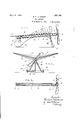
- a stopper 8 closes the front end of the tube, and a stopper 9 closes its rear end.
- a propeller i0 is provided, and is secured on a shaft 12 which is 'ournaled in the front stopper *8 w on the axis of the tube. Both stoppers are preferably formed of cork, or similar light material.
- An anchor hook it is secured in the rear stopper 9, and 15 is an elastic rubher band the ends of which are looped over the hook it and over a hook it on the rear end of the shaft 12.
- Thin washers l? are interposed between the hub of the propeller and the front sto per, so that the frlctio is reduced as none as possible.
- e propeller is revolved by hand so that the two stretches of the rubber band are wound together spirally, as shown in Fig. 3, and w on the propeller is released, the unwinding of the elastic spring afiords the ower which causes the air plane to fly.
- e air plane is provided wit air plane members, comprising preferabl two or i more win 20 and a tail-21, which are secured to t e upr side of the tube 7.
- These 59 parts maybe gued directly to the tube, or they may be secured to it by short pillars 24 of cork or the may be otherwise secured in p ace.
- the wings and tail may be arranged the same plane, or they may a be arranged at any slight angle to each other. They may be shaped to simulate I F.
- LAU-v any sort of a bird, butterfly, or other flying creature, or may be of conventional outline, and they may be colored and ornamented in any way desired.
- the air plane members are formed of paper, or other light material, and the wings preferably have stifi'ening bars 25 secured to them, and arranged laterally of the center tube. These bars are preferably formed of paper, and are hollow, and triangular in cross-section, and the longer bars which extend to the tips of the wings are tapered.
- a center late or rudder 26 is secured vertically un er the, rear end portion of the tube 7, and is also formed of; pa er, and is secured to the tail 21, by struts 2 of paper or other light material.
- the front end portion of the tube 7 has two downwardly and outwardly projecting le 28 secured to it, and strengthened by a och 29 of cork, secured to the tube between the le
- a shaft 30 is journaled horizontally in the lower end portions of the le s 28, and has wheels 31 of cork or other .i ht material secured on its end portions.
- the air plane rests on the two wheels 31 and the center plate 26 when stood on a flat surface, as shown in Fig. l.
- the spring is then wound up, and upon the release of the air lane from the hands, it rises in the air and flies for a considerable distance, according to its proportions and the strenpth of the elastic spring.
- the tube is norma ly supported in an upwardl and forwardly incllned position, so that t e air lane may rise in the air when released.
- he direction oi flight can be varled by nding the air plane members and center plate in a suitable way relative to each other and to the tube.
- a toy air plane a body, a ropeller shaft journaled at the front end t erect, a rubber band motor inclosed in the body and operating to revolve the said shaft, and air lane members secured to thetop side of the dy and rovided with hollow strength ening bars of? light material, triangular in cross-section, secured to their 11 per surfaces and extending laterally of the y.
- a body In a toy air plane, a body, a propeller shaft journaled at the front end thereof, a rubber band motor. inclosed in the body and operating to revolve the said shaft, a
Landscapes
- Toys (AREA)
Description
Sept 29 192 1. somez 8. IF. LAUKANDT TOY AIRPLANE Filed march 11, 1924 2 sheen-shew 1 sejato z 1924. 1,507,192
8. F. LAUKANDT TOY AIRPLANE Filed March 11-, 1924 2 Shoots-Sheet. 2
Patented Sept. 2, 1924.
BEBNHABJ) FRANK L AUKANDT, 01 RED WING, MINNESOTA.
TOY A r Application filed March 11, was. swarm. ceases.
To all whom it may concern:
Be it lmown that I, Barn KANDT, a citizen of the United States, residing at Red Wing, in the county of Good- 5 hue and State of Minnesota, have invented certain new and useful improvements in lby Airplanes, of which the following is a specification.
This invention relates to toy air planes provided with springs for operating them,
. and adapted to by in the air when properly wound up and released; and it consists in the novel construction and combination of Q light material, such as paper. A stopper 8 closes the front end of the tube, and a stopper 9 closes its rear end. A propeller i0 is provided, and is secured on a shaft 12 which is 'ournaled in the front stopper *8 w on the axis of the tube. Both stoppers are preferably formed of cork, or similar light material. An anchor hook it is secured in the rear stopper 9, and 15 is an elastic rubher band the ends of which are looped over the hook it and over a hook it on the rear end of the shaft 12. Thin washers l? are interposed between the hub of the propeller and the front sto per, so that the frlctio is reduced as none as possible.
. e propeller is revolved by hand so that the two stretches of the rubber band are wound together spirally, as shown in Fig. 3, and w on the propeller is released, the unwinding of the elastic spring afiords the ower which causes the air plane to fly. e air plane is provided wit air plane members, comprising preferabl two or i more win 20 and a tail-21, which are secured to t e upr side of the tube 7. These 59 parts maybe gued directly to the tube, or they may be secured to it by short pillars 24 of cork or the may be otherwise secured in p ace. The wings and tail may be arranged the same plane, or they may a be arranged at any slight angle to each other. They may be shaped to simulate I F. LAU-v any sort of a bird, butterfly, or other flying creature, or may be of conventional outline, and they may be colored and ornamented in any way desired.
The air plane members are formed of paper, or other light material, and the wings preferably have stifi'ening bars 25 secured to them, and arranged laterally of the center tube. These bars are preferably formed of paper, and are hollow, and triangular in cross-section, and the longer bars which extend to the tips of the wings are tapered. A center late or rudder 26 is secured vertically un er the, rear end portion of the tube 7, and is also formed of; pa er, and is secured to the tail 21, by struts 2 of paper or other light material. i
The front end portion of the tube 7 has two downwardly and outwardly projecting le 28 secured to it, and strengthened by a och 29 of cork, secured to the tube between the le A shaft 30 is journaled horizontally in the lower end portions of the le s 28, and has wheels 31 of cork or other .i ht material secured on its end portions. the air plane rests on the two wheels 31 and the center plate 26 when stood on a flat surface, as shown in Fig. l. The spring is then wound up, and upon the release of the air lane from the hands, it rises in the air and flies for a considerable distance, according to its proportions and the strenpth of the elastic spring. The tube is norma ly supported in an upwardl and forwardly incllned position, so that t e air lane may rise in the air when released.
he direction oi flight can be varled by nding the air plane members and center plate in a suitable way relative to each other and to the tube.
at I claim is:
1. ln a toy air plane, a body, a ropeller shaft journaled at the front end t erect, a rubber band motor inclosed in the body and operating to revolve the said shaft, and air lane members secured to thetop side of the dy and rovided with hollow strength ening bars of? light material, triangular in cross-section, secured to their 11 per surfaces and extending laterally of the y.
2. In a toy air plane, a body, a propeller shaft journaled at the front end thereof, a rubber band motor. inclosed in the body and operating to revolve the said shaft, a
loo
series of short pillars of light material and having also a vertical center plate sespaced apart longitudinally of and secured cured to the underside of the body below the to the top side of the said body, wings artail, and struts secured betweenthe said 1 ranged at an angle to each other, and a tail center plate and tail. 5 arranged parallel to the body, said wings In testimony whereof "I have afiixed my and tail being securedto the said illars. signature. I 3. Atoy air plane as set forth in c aim 2, BERNHARD FRANK LAUKANDT.
Priority Applications (1)
| Application Number | Priority Date | Filing Date | Title |
|---|---|---|---|
| US698383A US1507192A (en) | 1924-03-11 | 1924-03-11 | Toy airplane |
Applications Claiming Priority (1)
| Application Number | Priority Date | Filing Date | Title |
|---|---|---|---|
| US698383A US1507192A (en) | 1924-03-11 | 1924-03-11 | Toy airplane |
Publications (1)
| Publication Number | Publication Date |
|---|---|
| US1507192A true US1507192A (en) | 1924-09-02 |
Family
ID=24805002
Family Applications (1)
| Application Number | Title | Priority Date | Filing Date |
|---|---|---|---|
| US698383A Expired - Lifetime US1507192A (en) | 1924-03-11 | 1924-03-11 | Toy airplane |
Country Status (1)
| Country | Link |
|---|---|
| US (1) | US1507192A (en) |
Cited By (8)
| Publication number | Priority date | Publication date | Assignee | Title |
|---|---|---|---|---|
| US3251154A (en) * | 1964-07-13 | 1966-05-17 | Vincent D Taylor | Novelty cap apparatus |
| US3787997A (en) * | 1971-07-06 | 1974-01-29 | J Lemelson | Model airplane structures |
| US5775917A (en) * | 1996-07-24 | 1998-07-07 | Lou-Vee-Air Systems L L C | Propeller-driven educational vehicle apparatus |
| WO2002094403A2 (en) * | 2001-05-22 | 2002-11-28 | Dixon-Manning Limited | Toy aircraft with elastic band motor |
| US20050191931A1 (en) * | 2004-02-27 | 2005-09-01 | Gregory Ivan D. | Elastic drive motor with force isolation |
| US20080125002A1 (en) * | 2006-11-29 | 2008-05-29 | Shai Goitein | Paper flying toy |
| US8991758B2 (en) | 2013-05-13 | 2015-03-31 | Precisionhawk Inc. | Unmanned aerial vehicle |
| US9352241B1 (en) * | 2015-01-07 | 2016-05-31 | James C Gast | Rubber band powered toy vehicle |
-
1924
- 1924-03-11 US US698383A patent/US1507192A/en not_active Expired - Lifetime
Cited By (10)
| Publication number | Priority date | Publication date | Assignee | Title |
|---|---|---|---|---|
| US3251154A (en) * | 1964-07-13 | 1966-05-17 | Vincent D Taylor | Novelty cap apparatus |
| US3787997A (en) * | 1971-07-06 | 1974-01-29 | J Lemelson | Model airplane structures |
| US5775917A (en) * | 1996-07-24 | 1998-07-07 | Lou-Vee-Air Systems L L C | Propeller-driven educational vehicle apparatus |
| WO2002094403A2 (en) * | 2001-05-22 | 2002-11-28 | Dixon-Manning Limited | Toy aircraft with elastic band motor |
| WO2002094403A3 (en) * | 2001-05-22 | 2003-03-20 | Dixon Manning Ltd | Toy aircraft with elastic band motor |
| US20050191931A1 (en) * | 2004-02-27 | 2005-09-01 | Gregory Ivan D. | Elastic drive motor with force isolation |
| US6948997B2 (en) | 2004-02-27 | 2005-09-27 | Gregory Ivan D | Elastic drive motor with force isolation |
| US20080125002A1 (en) * | 2006-11-29 | 2008-05-29 | Shai Goitein | Paper flying toy |
| US8991758B2 (en) | 2013-05-13 | 2015-03-31 | Precisionhawk Inc. | Unmanned aerial vehicle |
| US9352241B1 (en) * | 2015-01-07 | 2016-05-31 | James C Gast | Rubber band powered toy vehicle |
Similar Documents
| Publication | Publication Date | Title |
|---|---|---|
| US3590518A (en) | Flying saucer craft | |
| US3177612A (en) | Toy airplane with automatic pilot ejector | |
| US5284454A (en) | Toy helicopter | |
| US1507192A (en) | Toy airplane | |
| US2324022A (en) | Aerial device | |
| US2439143A (en) | Toy helicopter | |
| US3264777A (en) | Game projectile having adjustable ailerons | |
| US3754349A (en) | Multiple use toy | |
| US1938931A (en) | Parachute toy | |
| US2382347A (en) | Toy helicopter | |
| US2303965A (en) | String propelled toy airplane | |
| US3912204A (en) | Captive airfoil apparatus | |
| US3553884A (en) | Toy aerodynamic wing | |
| US3696822A (en) | Flying toy | |
| US1842434A (en) | Foldable toy monoplane | |
| US2078374A (en) | Arrow glider | |
| US2587699A (en) | Parachute attachment for model gliders | |
| US1446110A (en) | Model or toy airplane | |
| US2349417A (en) | Toy kite | |
| US1420194A (en) | Toy aeroplane | |
| US1374000A (en) | Toy aeroplane | |
| US1680689A (en) | Toy glider | |
| US3514059A (en) | Turbocopter kite | |
| US20180133609A1 (en) | Self-Flapping Bird Wing Device | |
| US1470934A (en) | Toy airplane |