US8968382B2 - Method and apparatus for restricting flow through an opening in the side wall - Google Patents
Method and apparatus for restricting flow through an opening in the side wall Download PDFInfo
- Publication number
- US8968382B2 US8968382B2 US13/648,177 US201213648177A US8968382B2 US 8968382 B2 US8968382 B2 US 8968382B2 US 201213648177 A US201213648177 A US 201213648177A US 8968382 B2 US8968382 B2 US 8968382B2
- Authority
- US
- United States
- Prior art keywords
- flow
- aneurysm
- restricting face
- blood vessel
- closed loop
- Prior art date
- Legal status (The legal status is an assumption and is not a legal conclusion. Google has not performed a legal analysis and makes no representation as to the accuracy of the status listed.)
- Active, expires
Links
Images


Classifications
-
- A—HUMAN NECESSITIES
- A61—MEDICAL OR VETERINARY SCIENCE; HYGIENE
- A61B—DIAGNOSIS; SURGERY; IDENTIFICATION
- A61B17/00—Surgical instruments, devices or methods, e.g. tourniquets
- A61B17/12—Surgical instruments, devices or methods, e.g. tourniquets for ligaturing or otherwise compressing tubular parts of the body, e.g. blood vessels, umbilical cord
- A61B17/12022—Occluding by internal devices, e.g. balloons or releasable wires
- A61B17/12099—Occluding by internal devices, e.g. balloons or releasable wires characterised by the location of the occluder
- A61B17/12109—Occluding by internal devices, e.g. balloons or releasable wires characterised by the location of the occluder in a blood vessel
- A61B17/12113—Occluding by internal devices, e.g. balloons or releasable wires characterised by the location of the occluder in a blood vessel within an aneurysm
-
- A—HUMAN NECESSITIES
- A61—MEDICAL OR VETERINARY SCIENCE; HYGIENE
- A61B—DIAGNOSIS; SURGERY; IDENTIFICATION
- A61B17/00—Surgical instruments, devices or methods, e.g. tourniquets
- A61B17/12—Surgical instruments, devices or methods, e.g. tourniquets for ligaturing or otherwise compressing tubular parts of the body, e.g. blood vessels, umbilical cord
- A61B17/12022—Occluding by internal devices, e.g. balloons or releasable wires
- A61B17/12099—Occluding by internal devices, e.g. balloons or releasable wires characterised by the location of the occluder
- A61B17/12109—Occluding by internal devices, e.g. balloons or releasable wires characterised by the location of the occluder in a blood vessel
- A61B17/12113—Occluding by internal devices, e.g. balloons or releasable wires characterised by the location of the occluder in a blood vessel within an aneurysm
- A61B17/12118—Occluding by internal devices, e.g. balloons or releasable wires characterised by the location of the occluder in a blood vessel within an aneurysm for positioning in conjunction with a stent
-
- A—HUMAN NECESSITIES
- A61—MEDICAL OR VETERINARY SCIENCE; HYGIENE
- A61B—DIAGNOSIS; SURGERY; IDENTIFICATION
- A61B17/00—Surgical instruments, devices or methods, e.g. tourniquets
- A61B17/12—Surgical instruments, devices or methods, e.g. tourniquets for ligaturing or otherwise compressing tubular parts of the body, e.g. blood vessels, umbilical cord
- A61B17/12022—Occluding by internal devices, e.g. balloons or releasable wires
- A61B17/12131—Occluding by internal devices, e.g. balloons or releasable wires characterised by the type of occluding device
- A61B17/1214—Coils or wires
-
- A—HUMAN NECESSITIES
- A61—MEDICAL OR VETERINARY SCIENCE; HYGIENE
- A61B—DIAGNOSIS; SURGERY; IDENTIFICATION
- A61B17/00—Surgical instruments, devices or methods, e.g. tourniquets
- A61B17/12—Surgical instruments, devices or methods, e.g. tourniquets for ligaturing or otherwise compressing tubular parts of the body, e.g. blood vessels, umbilical cord
- A61B17/12022—Occluding by internal devices, e.g. balloons or releasable wires
- A61B17/12131—Occluding by internal devices, e.g. balloons or releasable wires characterised by the type of occluding device
- A61B17/12168—Occluding by internal devices, e.g. balloons or releasable wires characterised by the type of occluding device having a mesh structure
- A61B17/12172—Occluding by internal devices, e.g. balloons or releasable wires characterised by the type of occluding device having a mesh structure having a pre-set deployed three-dimensional shape
-
- A—HUMAN NECESSITIES
- A61—MEDICAL OR VETERINARY SCIENCE; HYGIENE
- A61F—FILTERS IMPLANTABLE INTO BLOOD VESSELS; PROSTHESES; DEVICES PROVIDING PATENCY TO, OR PREVENTING COLLAPSING OF, TUBULAR STRUCTURES OF THE BODY, e.g. STENTS; ORTHOPAEDIC, NURSING OR CONTRACEPTIVE DEVICES; FOMENTATION; TREATMENT OR PROTECTION OF EYES OR EARS; BANDAGES, DRESSINGS OR ABSORBENT PADS; FIRST-AID KITS
- A61F2/00—Filters implantable into blood vessels; Prostheses, i.e. artificial substitutes or replacements for parts of the body; Appliances for connecting them with the body; Devices providing patency to, or preventing collapsing of, tubular structures of the body, e.g. stents
- A61F2/82—Devices providing patency to, or preventing collapsing of, tubular structures of the body, e.g. stents
- A61F2/86—Stents in a form characterised by the wire-like elements; Stents in the form characterised by a net-like or mesh-like structure
-
- A—HUMAN NECESSITIES
- A61—MEDICAL OR VETERINARY SCIENCE; HYGIENE
- A61B—DIAGNOSIS; SURGERY; IDENTIFICATION
- A61B17/00—Surgical instruments, devices or methods, e.g. tourniquets
- A61B2017/00831—Material properties
- A61B2017/00867—Material properties shape memory effect
-
- A—HUMAN NECESSITIES
- A61—MEDICAL OR VETERINARY SCIENCE; HYGIENE
- A61B—DIAGNOSIS; SURGERY; IDENTIFICATION
- A61B17/00—Surgical instruments, devices or methods, e.g. tourniquets
- A61B2017/00831—Material properties
- A61B2017/00867—Material properties shape memory effect
- A61B2017/00871—Material properties shape memory effect polymeric
-
- A—HUMAN NECESSITIES
- A61—MEDICAL OR VETERINARY SCIENCE; HYGIENE
- A61B—DIAGNOSIS; SURGERY; IDENTIFICATION
- A61B17/00—Surgical instruments, devices or methods, e.g. tourniquets
- A61B17/12—Surgical instruments, devices or methods, e.g. tourniquets for ligaturing or otherwise compressing tubular parts of the body, e.g. blood vessels, umbilical cord
- A61B17/12022—Occluding by internal devices, e.g. balloons or releasable wires
- A61B2017/1205—Introduction devices
- A61B2017/12054—Details concerning the detachment of the occluding device from the introduction device
-
- A—HUMAN NECESSITIES
- A61—MEDICAL OR VETERINARY SCIENCE; HYGIENE
- A61F—FILTERS IMPLANTABLE INTO BLOOD VESSELS; PROSTHESES; DEVICES PROVIDING PATENCY TO, OR PREVENTING COLLAPSING OF, TUBULAR STRUCTURES OF THE BODY, e.g. STENTS; ORTHOPAEDIC, NURSING OR CONTRACEPTIVE DEVICES; FOMENTATION; TREATMENT OR PROTECTION OF EYES OR EARS; BANDAGES, DRESSINGS OR ABSORBENT PADS; FIRST-AID KITS
- A61F2/00—Filters implantable into blood vessels; Prostheses, i.e. artificial substitutes or replacements for parts of the body; Appliances for connecting them with the body; Devices providing patency to, or preventing collapsing of, tubular structures of the body, e.g. stents
- A61F2/82—Devices providing patency to, or preventing collapsing of, tubular structures of the body, e.g. stents
- A61F2/86—Stents in a form characterised by the wire-like elements; Stents in the form characterised by a net-like or mesh-like structure
- A61F2/90—Stents in a form characterised by the wire-like elements; Stents in the form characterised by a net-like or mesh-like structure characterised by a net-like or mesh-like structure
- A61F2/91—Stents in a form characterised by the wire-like elements; Stents in the form characterised by a net-like or mesh-like structure characterised by a net-like or mesh-like structure made from perforated sheet material or tubes, e.g. perforated by laser cuts or etched holes
-
- A—HUMAN NECESSITIES
- A61—MEDICAL OR VETERINARY SCIENCE; HYGIENE
- A61F—FILTERS IMPLANTABLE INTO BLOOD VESSELS; PROSTHESES; DEVICES PROVIDING PATENCY TO, OR PREVENTING COLLAPSING OF, TUBULAR STRUCTURES OF THE BODY, e.g. STENTS; ORTHOPAEDIC, NURSING OR CONTRACEPTIVE DEVICES; FOMENTATION; TREATMENT OR PROTECTION OF EYES OR EARS; BANDAGES, DRESSINGS OR ABSORBENT PADS; FIRST-AID KITS
- A61F2/00—Filters implantable into blood vessels; Prostheses, i.e. artificial substitutes or replacements for parts of the body; Appliances for connecting them with the body; Devices providing patency to, or preventing collapsing of, tubular structures of the body, e.g. stents
- A61F2/95—Instruments specially adapted for placement or removal of stents or stent-grafts
-
- A—HUMAN NECESSITIES
- A61—MEDICAL OR VETERINARY SCIENCE; HYGIENE
- A61F—FILTERS IMPLANTABLE INTO BLOOD VESSELS; PROSTHESES; DEVICES PROVIDING PATENCY TO, OR PREVENTING COLLAPSING OF, TUBULAR STRUCTURES OF THE BODY, e.g. STENTS; ORTHOPAEDIC, NURSING OR CONTRACEPTIVE DEVICES; FOMENTATION; TREATMENT OR PROTECTION OF EYES OR EARS; BANDAGES, DRESSINGS OR ABSORBENT PADS; FIRST-AID KITS
- A61F2/00—Filters implantable into blood vessels; Prostheses, i.e. artificial substitutes or replacements for parts of the body; Appliances for connecting them with the body; Devices providing patency to, or preventing collapsing of, tubular structures of the body, e.g. stents
- A61F2/02—Prostheses implantable into the body
- A61F2/30—Joints
- A61F2002/30001—Additional features of subject-matter classified in A61F2/28, A61F2/30 and subgroups thereof
- A61F2002/30108—Shapes
- A61F2002/30199—Three-dimensional shapes
- A61F2002/30242—Three-dimensional shapes spherical
-
- A—HUMAN NECESSITIES
- A61—MEDICAL OR VETERINARY SCIENCE; HYGIENE
- A61F—FILTERS IMPLANTABLE INTO BLOOD VESSELS; PROSTHESES; DEVICES PROVIDING PATENCY TO, OR PREVENTING COLLAPSING OF, TUBULAR STRUCTURES OF THE BODY, e.g. STENTS; ORTHOPAEDIC, NURSING OR CONTRACEPTIVE DEVICES; FOMENTATION; TREATMENT OR PROTECTION OF EYES OR EARS; BANDAGES, DRESSINGS OR ABSORBENT PADS; FIRST-AID KITS
- A61F2/00—Filters implantable into blood vessels; Prostheses, i.e. artificial substitutes or replacements for parts of the body; Appliances for connecting them with the body; Devices providing patency to, or preventing collapsing of, tubular structures of the body, e.g. stents
- A61F2/82—Devices providing patency to, or preventing collapsing of, tubular structures of the body, e.g. stents
- A61F2002/823—Stents, different from stent-grafts, adapted to cover an aneurysm
-
- A—HUMAN NECESSITIES
- A61—MEDICAL OR VETERINARY SCIENCE; HYGIENE
- A61F—FILTERS IMPLANTABLE INTO BLOOD VESSELS; PROSTHESES; DEVICES PROVIDING PATENCY TO, OR PREVENTING COLLAPSING OF, TUBULAR STRUCTURES OF THE BODY, e.g. STENTS; ORTHOPAEDIC, NURSING OR CONTRACEPTIVE DEVICES; FOMENTATION; TREATMENT OR PROTECTION OF EYES OR EARS; BANDAGES, DRESSINGS OR ABSORBENT PADS; FIRST-AID KITS
- A61F2/00—Filters implantable into blood vessels; Prostheses, i.e. artificial substitutes or replacements for parts of the body; Appliances for connecting them with the body; Devices providing patency to, or preventing collapsing of, tubular structures of the body, e.g. stents
- A61F2/95—Instruments specially adapted for placement or removal of stents or stent-grafts
- A61F2002/9505—Instruments specially adapted for placement or removal of stents or stent-grafts having retaining means other than an outer sleeve, e.g. male-female connector between stent and instrument
-
- A—HUMAN NECESSITIES
- A61—MEDICAL OR VETERINARY SCIENCE; HYGIENE
- A61F—FILTERS IMPLANTABLE INTO BLOOD VESSELS; PROSTHESES; DEVICES PROVIDING PATENCY TO, OR PREVENTING COLLAPSING OF, TUBULAR STRUCTURES OF THE BODY, e.g. STENTS; ORTHOPAEDIC, NURSING OR CONTRACEPTIVE DEVICES; FOMENTATION; TREATMENT OR PROTECTION OF EYES OR EARS; BANDAGES, DRESSINGS OR ABSORBENT PADS; FIRST-AID KITS
- A61F2230/00—Geometry of prostheses classified in groups A61F2/00 - A61F2/26 or A61F2/82 or A61F9/00 or A61F11/00 or subgroups thereof
- A61F2230/0002—Two-dimensional shapes, e.g. cross-sections
- A61F2230/0028—Shapes in the form of latin or greek characters
- A61F2230/005—Rosette-shaped, e.g. star-shaped
-
- A—HUMAN NECESSITIES
- A61—MEDICAL OR VETERINARY SCIENCE; HYGIENE
- A61F—FILTERS IMPLANTABLE INTO BLOOD VESSELS; PROSTHESES; DEVICES PROVIDING PATENCY TO, OR PREVENTING COLLAPSING OF, TUBULAR STRUCTURES OF THE BODY, e.g. STENTS; ORTHOPAEDIC, NURSING OR CONTRACEPTIVE DEVICES; FOMENTATION; TREATMENT OR PROTECTION OF EYES OR EARS; BANDAGES, DRESSINGS OR ABSORBENT PADS; FIRST-AID KITS
- A61F2230/00—Geometry of prostheses classified in groups A61F2/00 - A61F2/26 or A61F2/82 or A61F9/00 or A61F11/00 or subgroups thereof
- A61F2230/0063—Three-dimensional shapes
- A61F2230/0071—Three-dimensional shapes spherical
-
- A—HUMAN NECESSITIES
- A61—MEDICAL OR VETERINARY SCIENCE; HYGIENE
- A61F—FILTERS IMPLANTABLE INTO BLOOD VESSELS; PROSTHESES; DEVICES PROVIDING PATENCY TO, OR PREVENTING COLLAPSING OF, TUBULAR STRUCTURES OF THE BODY, e.g. STENTS; ORTHOPAEDIC, NURSING OR CONTRACEPTIVE DEVICES; FOMENTATION; TREATMENT OR PROTECTION OF EYES OR EARS; BANDAGES, DRESSINGS OR ABSORBENT PADS; FIRST-AID KITS
- A61F2230/00—Geometry of prostheses classified in groups A61F2/00 - A61F2/26 or A61F2/82 or A61F9/00 or A61F11/00 or subgroups thereof
- A61F2230/0063—Three-dimensional shapes
- A61F2230/0091—Three-dimensional shapes helically-coiled or spirally-coiled, i.e. having a 2-D spiral cross-section
-
- A—HUMAN NECESSITIES
- A61—MEDICAL OR VETERINARY SCIENCE; HYGIENE
- A61F—FILTERS IMPLANTABLE INTO BLOOD VESSELS; PROSTHESES; DEVICES PROVIDING PATENCY TO, OR PREVENTING COLLAPSING OF, TUBULAR STRUCTURES OF THE BODY, e.g. STENTS; ORTHOPAEDIC, NURSING OR CONTRACEPTIVE DEVICES; FOMENTATION; TREATMENT OR PROTECTION OF EYES OR EARS; BANDAGES, DRESSINGS OR ABSORBENT PADS; FIRST-AID KITS
- A61F2230/00—Geometry of prostheses classified in groups A61F2/00 - A61F2/26 or A61F2/82 or A61F9/00 or A61F11/00 or subgroups thereof
- A61F2230/0063—Three-dimensional shapes
- A61F2230/0095—Saddle-shaped
Definitions
- This invention relates to medical procedures and apparatus in general, and more particularly to medical procedures and apparatus for restricting flow through an opening in the side wall of a body lumen, and/or for reinforcing a weakness in the side wall of a body lumen, while still maintaining substantially normal flow through the body lumen.
- the human body consists of many different anatomical structures.
- these anatomical structures are the blood vessels which circulate blood throughout the body, i.e., the arteries which deliver oxygenated blood to the end tissues and the veins which return oxygen-depleted blood from the end tissues.
- a blood vessel can become weakened, thereby causing the side wall of the blood vessel to balloon outwardly so as to create an aneurysm.
- FIGS. 1-3 show various types of aneurysms, e.g., a fusiform aneurysm ( FIG. 1 ), where the aneurysm extends around a substantial portion of the circumference of a blood vessel; a lateral aneurysm ( FIG. 2 ), where the aneurysm extends out of a limited portion of the side wall of a blood vessel, with a well-defined neck; and a bifurcation aneurysm ( FIG.
- aneurysm extends out of the apex of a bifurcation of a blood vessel.
- all of these aneurysms e.g., fusiform aneurysms, lateral aneurysms and/or bifurcations aneurysms
- fusiform aneurysms e.g., fusiform aneurysms, lateral aneurysms and/or bifurcations aneurysms
- Aneurysms can present a serious threat to the patient, since they may enlarge to the point of rupture, thereby resulting in a rapid and uncontrolled loss of blood. Depending upon the size and location of the aneurysm, the aneurysm can be life-threatening.
- an intracranial aneurysm can be fatal if rupture occurs.
- these aneurysms have traditionally been treated with an open craniotomy and microsurgical clipping. This procedure generally involves placing a small titanium clip across the neck of the aneurysm, thus isolating the aneurysm from blood flow and inhibiting subsequent rupture (or re-rupture). This clipping procedure is typically done under direct visualization, using an operating microscope.
- minimally-invasive techniques have also been used to treat both ruptured and un-ruptured brain aneurysms.
- These minimally-invasive techniques generally employ interventional neuroradiological procedures utilizing digital fluoroscopy. More particularly, these interventional neuroradiological procedures generally use X-ray visualization to allow the surgeon to place a microcatheter within the dome of the aneurysm. With the microcatheter in place, detachable coils are then deployed within the dome of the aneurysm, thereby reducing blood velocity within the dome of the aneurysm and causing thrombosis of the aneurysm so as to prevent subsequent rupture (or re-rupture).
- this coil-depositing procedure has a number of drawbacks, including the risk of coil herniation into the lumen of the blood vessel; the risk of coil migration out of the aneurysm and into the blood vessel, with subsequent downstream migration; the risk of aneurysm rupture; etc.
- a primary object of the present invention is to provide a new and improved device, adapted for minimally-invasive, endoluminal delivery, which may be used to restrict blood flow to an aneurysm while still maintaining substantially normal blood flow through the blood vessel.
- Another object of the present invention is to provide a new and improved device, adapted for minimally-invasive, endoluminal delivery, which may be used to reinforce a weakness in a side wall of a blood vessel while still maintaining substantially normal blood flow through the blood vessel.
- Another object of the present invention is to provide a new and improved device, adapted for minimally-invasive, endoluminal delivery, which may be used to facilitate the retention of detachable coils and/or other embolic material deployed within the interior of an aneurysm while still maintaining substantially normal flow through the blood vessel.
- a device for positioning within the lumen of a blood vessel, adjacent to the mouth of an aneurysm extending from the lumen of the blood vessel, for causing thrombosis of the aneurysm while maintaining substantially normal blood flow through the blood vessel comprising:
- a method for causing thrombosis of an aneurysm extending from the lumen of a blood vessel while maintaining substantially normal blood flow through the lumen of the blood vessel comprising:
- a system for treating a patient comprising:
- an inserter for carrying the device to a deployment site wherein the installation tool comprises:
- FIGS. 1-3 are schematic views showing various types of aneurysms
- FIGS. 4-8 are schematic views showing a novel expandable spherical structure formed in accordance with the present invention, wherein the expandable spherical structure comprises an open frame with a flow-restricting face (i.e., a closed face in this particular embodiment), and wherein the expandable spherical structure is shown being used to close off a lateral aneurysm in a blood vessel;
- the expandable spherical structure comprises an open frame with a flow-restricting face (i.e., a closed face in this particular embodiment), and wherein the expandable spherical structure is shown being used to close off a lateral aneurysm in a blood vessel;
- FIGS. 9-13 are schematic views showing another novel expandable spherical structure formed in accordance with the present invention, wherein the expandable spherical structure comprises an open frame with a flow-restricting face (i.e., a closed face in this particular embodiment), wherein the open frame is formed out of an absorbable material and the closed face is formed out of a non-absorbable material, and wherein the expandable spherical structure is shown being used to close off a lateral aneurysm in a blood vessel;
- a flow-restricting face i.e., a closed face in this particular embodiment
- FIGS. 14-18 are schematic views showing the expandable spherical structure of FIGS. 4-8 being used to close off a bifurcation aneurysm;
- FIGS. 19-23 are schematic views showing the expandable spherical structure of FIGS. 9-13 being used to close off a bifurcation aneurysm;
- FIG. 24 is a schematic view showing another novel expandable spherical structure formed in accordance with the present invention, wherein the expandable spherical structure comprises an open frame with a flow-restricting face (i.e., a closed face in this particular embodiment), and wherein the open frame of the expandable spherical structure comprises a plurality of struts arranged in a rectangular pattern;
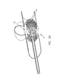
- FIG. 25 is a schematic view showing another novel expandable spherical structure formed in accordance with the present invention, wherein the open frame comprises a plurality of struts arranged in a hexagonal pattern;
- FIG. 26 is a schematic view showing another novel expandable spherical structure formed in accordance with the present invention, wherein the expandable spherical structure comprises an open frame with a flow-restricting face (i.e., a closed face in this particular embodiment), and wherein the open frame of the expandable spherical structure comprises a spherical spiral;
- the expandable spherical structure comprises an open frame with a flow-restricting face (i.e., a closed face in this particular embodiment), and wherein the open frame of the expandable spherical structure comprises a spherical spiral;
- FIG. 27 is a schematic view showing another novel expandable spherical structure formed in accordance with the present invention, wherein the expandable spherical structure comprises an open frame with a flow-restricting face (i.e., a closed face in this particular embodiment), and wherein the open frame of the expandable spherical structure comprises a spherical cage;
- the expandable spherical structure comprises an open frame with a flow-restricting face (i.e., a closed face in this particular embodiment), and wherein the open frame of the expandable spherical structure comprises a spherical cage;
- FIGS. 28-37 are schematic views showing other novel expandable spherical structures formed in accordance with the present invention, wherein the expandable spherical structures comprise spherical cages;
- FIGS. 38-43 are schematic views showing other novel expandable spherical structures formed in accordance with the present invention, wherein the expandable spherical structure comprises an open frame with a flow-restricting face (i.e., a closed face in this particular embodiment), and wherein the flow-restricting face is disposed to one side of the axis of approach;
- the expandable spherical structure comprises an open frame with a flow-restricting face (i.e., a closed face in this particular embodiment), and wherein the flow-restricting face is disposed to one side of the axis of approach;
- FIGS. 44 and 45 are schematic views showing the expandable spherical structure of FIG. 27 being deployed with a syringe-type (e.g., an outer sleeve with an internal pusher) installation tool;
- a syringe-type e.g., an outer sleeve with an internal pusher
- FIG. 46 is a schematic view showing the expandable spherical structure of FIG. 27 being deployed with a syringe-type installation tool equipped with a gripper mechanism;
- FIGS. 47-49 are schematic views showing the expandable spherical structure of FIG. 27 being deployed with a syringe-type installation tool equipped with an expansion balloon;
- FIGS. 50-54 are schematic views showing another novel expandable spherical structure formed in accordance with the present invention, wherein the expandable spherical structure comprises an open frame with a flow-restricting face (i.e., a face having a high strut density in this particular embodiment), and wherein the expandable spherical structure is shown being used to restrict flow to a lateral aneurysm in a blood vessel;
- a flow-restricting face i.e., a face having a high strut density in this particular embodiment
- FIGS. 55-63 are schematic views showing other expandable spherical structures formed in accordance with the present invention, wherein the expandable spherical structures comprise open frames with flow-restricting faces (i.e., faces having high strut densities in these particular embodiments);
- FIGS. 64-66 are schematic views showing the expandable spherical structure of FIGS. 4-8 being deployed within the interior of a lateral aneurysm so as to close off the aneurysm;
- FIGS. 67-71 are schematic views showing the expandable spherical structure of FIGS. 9-13 being deployed within the interior of a lateral aneurysm so as to close off the aneurysm;
- FIGS. 72-76 are schematic views showing the expandable spherical structure of FIGS. 4-8 being deployed within the interior of a bifurcation aneurysm so as to close off the aneurysm;
- FIGS. 77-81 are schematic views showing the expandable spherical structure of FIGS. 9-13 being deployed within the interior of a bifurcation aneurysm so as to close off the aneurysm;
- FIGS. 82 and 83 are schematic views showing an expandable spherical structure having stabilizing legs extending therefrom so as to form a “comet-shaped” structure, with the structure being configured to restrict flow to a lateral aneurysm in a blood vessel;
- FIGS. 84-97 are schematic views showing various constructions for the “comet-shaped” structure of FIGS. 82 and 83 , but with the flow-restricting face of the expandable spherical structure being omitted in FIGS. 84-91 for clarity of viewing;
- FIG. 98 is a schematic view showing another comet-shaped structure, but with this structure being configured to restrict flow to a bifurcation aneurysm;
- FIGS. 99 and 100 show an expandable spherical structure restricting flow into a bifurcation aneurysm, where the expandable spherical structure is formed out of a “closed loop” of filament, and where the expandable spherical structure is deployed in the patient so that the face having a high strut density is positioned over the mouth/neck of the aneurysm in order to restrict flow into the aneurysm;
- FIGS. 101 and 102 are schematic views of an inserter which may be used with an expandable spherical structure formed out of a “closed loop” of filament;
- FIGS. 103-107 are schematic views showing how an expandable spherical structure formed out of a “closed loop” of filament may be deployed using the inserter of FIGS. 101 and 102 ;
- FIG. 108 is a schematic view showing an endoluminal device formed in accordance with the present invention.
- FIGS. 109-111 are schematic views showing another endoluminal device formed in accordance with the present invention.
- FIGS. 112-115 are schematic views showing the endoluminal device of FIGS. 109-111 deployed adjacent an aneurysm;
- FIGS. 116-118 are schematic views showing the endoluminal device of FIGS. 109-111 mounted to the inserter of FIGS. 101-107 ;
- FIGS. 119 and 120 are schematic views showing an alternative form of inserter
- FIGS. 121 and 122 are schematic views showing another alternative form of inserter
- FIGS. 123 and 124 are schematic views showing still another alternative form of inserter
- FIGS. 125 and 126 are schematic views showing yet another alternative form of inserter
- FIGS. 127-132 are schematic views showing another endoluminal device formed in accordance with the present invention.
- FIGS. 133-136 are schematic views showing the endoluminal device of FIGS. 127-132 deployed adjacent an aneurysm;
- FIGS. 137-140 are schematic views showing another endoluminal device formed in accordance with the present invention.
- FIGS. 141-144 are schematic views showing still another endoluminal device formed in accordance with the present invention.
- FIG. 145 is a schematic views showing yet another endoluminal device formed in accordance with the present invention.
- Expandable spherical structure 5 is adapted for minimally-invasive, endoluminal delivery into a blood vessel or other body lumen, for restricting flow through an opening in the side wall of the blood vessel or other body lumen, and/or for reinforcing a weakness in the side wall of the blood vessel or other body lumen, while still maintaining substantially normal flow through the blood vessel or other body lumen.
- Expandable spherical structure 5 generally comprises a spherical body comprising an open frame 10 with a flow-restricting face 15 (i.e., a closed face or a face having a high strut density).
- open frame 10 and flow-restricting face 15 together define the entire exterior shape of the spherical body, with open frame 10 making up the majority of the exterior shape of the spherical body.
- open frame 10 defines approximately 90% of the exterior shape of the spherical body and flow-restricting face 15 defines approximately 10% of the exterior shape of the spherical body. In another preferred form of the invention, open frame 10 defines approximately 80% of the exterior shape of the spherical body and flow-restricting face 15 defines approximately 20% of the exterior shape of the spherical body. In yet another preferred form of the invention, open frame 10 comprises approximately 70% of the exterior shape of the spherical body and flow-restricting face 15 defines approximately 30% of the exterior shape of the spherical body. And in yet another preferred form of the invention, open frame 10 comprises approximately 60% of the exterior shape of the spherical body and flow-restricting face 15 comprises approximately 40% of the exterior shape of the spherical body.
- Expandable spherical structure 5 is constructed so that it may be deployed in a blood vessel or other body lumen, by (i) collapsing the expandable spherical structure into a configuration of reduced dimension, (ii) moving the collapsed structure through the blood vessel or other body lumen to a therapy site, and (iii) expanding the collapsed structure to an enlarged dimension at the therapy site, whereby to secure the expandable spherical structure in the blood vessel or body lumen so that its flow-restricting face 15 is presented to a side wall of the blood vessel or other body lumen while open frame 10 spans the blood vessel or other body lumen and bears against opposing anatomy so as to support flow-restricting face 15 in position, whereby to restrict flow to an aneurysm or other opening in the side wall of the blood vessel or other body lumen, or to otherwise reinforce a weakness in the side wall of the blood vessel or other body lumen, without significantly impeding normal flow through the blood vessel or other body lumen.
- the endoluminal device is readily centered on the neck of an aneurysm or other opening in a body lumen, with flow-restricting face 15 projecting into the neck of the aneurysm or other opening in a body lumen and reliably restricting flow into the aneurysm or other opening in a body lumen.
- expandable spherical structure 5 is effectively self-sizing, since it can be expanded to the degree necessary to span the blood vessel or other body lumen.
- expandable spherical structure 5 generally comprises an open frame 10 which has a flow restricting face 15 (i.e., a closed face or a face having a high strut density) carried thereon.
- Open frame 10 is formed so that it can assume a first, collapsed configuration of reduced dimension ( FIG. 4 ) so as to facilitate moving expandable spherical structure 5 endoluminally through the blood vessel or other body lumen to the therapy site.
- Open frame 10 is also formed so that it can thereafter be re-configured to a second, expanded configuration of enlarged dimension ( FIGS.
- expandable spherical structure 5 can be lodged in the blood vessel or other body lumen at the therapy site, with its flow-restricting face 15 pressed securely against a side wall of the blood vessel or other body lumen while open frame 10 spans the blood vessel or other body lumen and bears against opposing anatomy so as to support flow-restricting face 15 in position.
- flow-restricting face 15 of expandable spherical structure 5 can restrict flow to an aneurysm in the blood vessel (such as the lateral aneurysm shown in FIGS.
- the endoluminal device can be collapsed to a reduced dimension for minimally-invasive, endoluminal delivery into a blood vessel or other body lumen, yet can thereafter be expanded to the required dimension for secure lodgement at the therapy site, whereby to restrict flow to an opening in a body lumen and/or to reinforce a weakness in the side wall of the body lumen.
- the endoluminal device is readily centered on the neck of an aneurysm or other opening in a body lumen, with flow-restricting face 15 projecting into the neck of the aneurysm or other opening in a body lumen and reliably restricting flow into the aneurysm or other opening in a body lumen.
- expandable spherical structure 5 By forming expandable spherical structure 5 so that it can expand at the therapy site and lodge itself in the blood vessel or other body lumen with its flow-restricting face 15 presented to a side wall of the blood vessel or other body lumen while open frame 10 spans the blood vessel or other body lumen and bears against opposing anatomy so as to support flow-restricting face 15 in position, expandable spherical structure 5 is effectively self-sizing, since it expands to the degree necessary to span the blood vessel or other body lumen.
- expandable spherical structure 5 can be disposed in the blood vessel or other body lumen and extend across the lumen of the blood vessel or other body lumen without significantly impeding normal flow through the blood vessel or other body lumen ( FIGS. 6-8 ).
- expandable spherical structure 5 generally comprises a spherical body comprising an open frame 10 with a flow-restricting face 15 (i.e., a closed face or a face having a high strut density); (ii) open frame 10 and flow-restricting face 15 together preferably define the entire exterior shape of the spherical body, with open frame 10 making up the majority of the exterior shape of the spherical body; (iii) open frame 10 is capable of being collapsed in dimension for easy delivery of expandable spherical structure 5 to the therapy site and thereafter expanded in dimension at the therapy site so as to hold flow-restricting face 15 against a side wall of a blood vessel or other body lumen; and (iv) open frame 10 is configured so that it does not significantly impede normal flow through the blood vessel or other body lumen within which it is deployed.
- a flow-restricting face 15 i.e., a closed face or a face having a high strut density
- open frame 10 is preferably formed with an expandable strut construction, so that it can (i) first assume a configuration of reduced dimension, so that expandable spherical body 5 can move easily through the body to the therapy site, and (ii) thereafter assume a configuration of expanded dimension, so that it can be securely retained at the desired location in the blood vessel or other body lumen and press flow-restricting face 15 securely against the side wall of the blood vessel or body lumen, whereby to restrict flow to an aneurysm or other opening in the blood vessel or other body lumen, or to otherwise reinforce the side wall of the blood vessel or other body lumen.
- open frame 10 is effectively self-sizing, since it expands to the degree necessary to span the blood vessel or other body lumen.
- open frame 10 does not significantly impede normal flow through the blood vessel or other body lumen when open frame 10 is in its expanded configuration within the blood vessel or other body lumen.
- open frame 10 comprises a plurality of struts arranged in a polygonal configuration, with the struts being sized so that the struts present minimal obstruction to normal flow through the lumen.
- open frame 10 may be formed out of a shape memory alloy (SMA) such as Nitinol, and a temperature transition may be used to change the configuration of open frame 10 .
- SMA shape memory alloy
- open frame 10 can be formed so that when it is cooled to a temperature below body temperature, the open frame assumes a collapsed configuration ( FIG. 4 ), and when it is thereafter warmed to body temperature, the open frame assumes an expanded configuration ( FIG. 6 ).
- open frame 10 can be warmed to body temperature simply by deploying expandable spherical structure 5 in the body.
- an electrical current may be applied to open frame 10 so as to heat open frame 10 to its expansion temperature, e.g., via resistance heating.
- a warm or cold saline solution can be flushed through open frame 10 so as to appropriately modulate the temperature of the open frame, whereby to cause the open frame to assume a desired configuration.
- open frame 10 can be formed out of a resilient material which can be forcibly compressed into a collapsed configuration, restrained in this collapsed configuration, and thereafter released so that it elastically returns to its expanded configuration.
- expandable spherical structure 5 might be compressed into a configuration of a reduced dimension, restrained within a sleeve, delivered to the therapy site within the sleeve, and then released from the sleeve so that it elastically returns to an expanded configuration at the therapy site, whereby to lodge itself in the blood vessel or other body lumen, with its flow-restricting face pressed against the side wall of the blood vessel or other body lumen while open frame 10 spans the blood vessel or other body lumen and bears against opposing anatomy so as to support flow-restricting face 15 in position.
- open frame 10 can be formed out of a shape memory alloy (SMA) engineered to form stress-induced martensite (SIM) and thereby exhibit superelastic properties, whereby to permit large shape deformations with elastic return.
- SMA shape memory alloy
- SIM stress-induced martensite
- open frame 10 can be formed out of a suitable polymer which exhibits the desired elastic properties.
- open frame 10 is formed with a structure which can be collapsed for delivery to the deployment site and thereafter enlarged to an expanded configuration through the use of an expansion device, e.g., an internal balloon, where the balloon is inflated at the therapy site so as to reconfigure open frame 10 to an expanded condition.
- an expansion device e.g., an internal balloon
- This arrangement can be advantageous, since it does not require the open frame to rely on temperature transition or elasticity to expand to its fully expanded configuration (or to any desired expanded configuration less than its fully expanded configuration).
- a wide range of well known biocompatible materials e.g., medical grade stainless steel may be used to form open frame 10 .
- Flow-restricting face 15 is carried by (e.g., mounted on, formed integral with, or otherwise connected to) open frame 10 so that flow-restricting face 15 can be pressed securely against the side wall of the blood vessel or other body lumen within which expandable spherical structure 5 is deployed.
- Flow-restricting face 15 may comprise a closed face, in the sense that it comprises a substantially complete surface or barrier which is capable of closing off an aneurysm or other opening in side wall of a blood vessel or other body lumen, and/or for reinforcing a weakness in the side wall of the blood vessel or other body lumen. See FIGS. 4-8 , where flow-restricting face 15 is depicted as a closed face.
- flow-restricting face 15 may comprise a face having a high strut density which is capable of restricting flow to an aneurysm or other opening in a side wall of a blood vessel or other body lumen, and/or for reinforcing a weakness in the side wall of the blood vessel or other body lumen.
- flow-restricting face 15 may not constitute a substantially complete surface, or flow-restricting face 15 may not constitute a substantially fluid-impervious surface, but flow-restricting face 15 will have a strut density sufficiently high to restrict flow through that face, e.g., so as to cause an aneurysm to thrombose.
- Flow-restricting face 15 may be formed so as to be substantially rigid or it may be formed so as to be flexible.
- Flow-restricting face 15 preferably has the convex configuration shown in FIGS. 4-8 , so that it can form a regular portion of the spherical body of expandable structure 5 .
- flow-restricting face 15 may also be formed with a planar configuration, or some other configuration, if desired.
- expandable spherical structure 5 can have some or all of its elements formed out of an absorbable material, so that some or all of the elements are removed from the therapy site after some period of time has elapsed.
- open frame 10 can be formed out of an absorbable material, and flow-restricting face 15 can be formed out of a non-absorbable material, so that only flow-restricting face 15 is retained at the therapy site after some period of time has passed. See FIGS. 9-13 .
- This type of construction can be advantageous where flow-restricting face 15 integrates into the side wall of the blood vessel or other body lumen after some period of time has elapsed, so that a supporting frame is no longer necessary to hold flow-restricting face 15 in position against the side wall of the blood vessel or other body lumen.
- the entire expandable spherical structure 5 can be formed out of absorbable material(s), i.e., with both open frame 10 and flow-restricting face 15 being formed out of absorbable materials.
- This type of construction can be advantageous where flow-restricting face 15 only needs to be held against the side wall of the blood vessel or other body lumen for a limited period of time, e.g., until aneurysm thrombosis/scarring is complete, or to reinforce the side wall of the blood vessel or other body lumen while healing occurs, etc.
- open frame 10 and flow-restricting face 15 are absorbable, they may be engineered so as to have different absorption rates, so that they are removed from the therapy site at different times. This may be done by making the various elements out of different materials, or by making the various elements out of different blends of the same materials, etc.
- expandable spherical structure 5 can be used to restrict flow to various types of aneurysms.
- FIGS. 4-8 and 9 - 13 show expandable spherical structure 5 being used to restrict flow to a lateral aneurysm (i.e., in these particular embodiments, to close off the lateral aneurysm).
- expandable spherical structure 5 may be used to restrict flow to a bifurcation aneurysm as well.
- FIGS. 14-18 show the expandable spherical structure 5 of FIGS. 4-8 being used restrict flow to a bifurcation aneurysm
- FIGS. 19-23 show the expandable spherical structure 5 of FIGS. 9-13 being used to restrict flow to a bifurcation aneurysm (i.e., in these particular embodiments, to close off the bifurcation aneurysm).
- the spherical shape of expandable spherical structure 5 is particularly well suited for use in treating bifurcation aneurysms, since it may be seated securely at the bifurcation, pressing flow-restricting face 15 securely against the bifurcation aneurysm, with open frame 10 spanning the blood vessel or other body lumen and bearing against opposing anatomy so as to support flow-restricting face 15 in position, while still allowing blood to flow substantially unobstructed through the blood vessels.
- expandable spherical structure 5 may be used to restrict flow to other types of aneurysms as well, e.g., certain forms of fusiform aneurysms.
- flow-restricting face 15 may comprise a significantly enlarged surface area, or flow-restricting face 15 may comprise two or more separated segments disposed about the lateral portions of open frame 10 , etc.
- open frame 10 can be formed with a variety of different configurations without departing from the scope of the present invention.
- open frame 10 may be formed out of a plurality of struts arranged in a polygonal array. See, for example, FIGS. 4-8 , 9 - 13 , 14 - 18 and 19 - 23 , where open frame 10 is shown formed out of a plurality of struts arranged as triangular polygons. See also FIG. 24 , where open frame 10 is formed out of a plurality of struts arranged as rectangular polygons, and FIG. 25 , where open frame 10 is formed out of a plurality of struts arranged as hexagons.
- open frame 10 with a non-polygonal structure.
- open frame 10 may be formed with a spherical spiral structure, e.g., such as is shown in FIG. 26 , where a spiral strut forms the open frame 10 .
- FIG. 27 shows an open frame 10 having a spherical cage structure. More particularly, in this construction, open frame 10 comprises a plurality of axially-aligned struts 20 which extend between flow-restricting face 15 and an annular ring 25 . Struts 20 preferably bow outwardly when open frame 10 is in its expanded configuration, but may be bent inwardly (e.g., to a straight or inwardly-bowed configuration) or otherwise deformed so as to permit open frame 10 to assume a reduced configuration. By way of example but not limitation, struts 20 may be bent inwardly (e.g., so as to extend substantially parallel to one another) when open frame 10 is in its reduced configuration.
- FIGS. 28-37 show other spherical cage constructions wherein various struts 20 form open frame 10 .
- flow-restricting face 15 sits at one end of the plurality of axially-aligned struts 20 and annular ring 25 sits at the opposing end of the plurality of axially-aligned struts 20 . Since struts 20 are intended to be bowed inwardly so that the expandable spherical structure can assume a reduced configuration, the spherical cage structure of FIG. 27 is generally intended to be delivered axially, with flow-restricting face 15 leading.
- this construction is particularly well suited for use with bifurcation aneurysms, where the neck of the aneurysm is typically axially-aligned with the direction of approach (see, for example, FIGS. 14-18 and 19 - 23 ). Accordingly, where the spherical cage structure is intended to be used with lateral aneurysms, it may be desirable to use the spherical cage configuration shown in FIG. 38 , where flow-restricting face 15 is disposed to one side of the axis of approach, i.e., to one side of the axis 27 shown in FIG. 38 .
- flow-restricting face 15 is intended to be aligned with the axis of approach
- flow-restricting face 15 is intended to be disposed to one side of the axis of approach. In this way, expandable spherical structure 5 can be endoluminally advanced to the therapy site and flow-restricting face 15 properly positioned relative to the anatomy.
- FIGS. 39-43 show other spherical cage constructions wherein various struts 20 form open frame 10 and flow-restricting face 15 is disposed to one side of the axis of approach.
- Various installation tools may be provided to deploy expandable spherical structure 5 within a blood vessel or other body lumen.
- FIG. 44 there is shown a syringe-type (e.g., an outer sleeve with an internal pusher) installation tool 100 for deploying the expandable spherical structure 5 shown in FIG. 45 .
- Installation tool 100 generally comprises a hollow sleeve 105 having a lumen 110 therein, and a pusher 115 slidably disposed within lumen 110 .
- Lumen 110 is sized so that it can accommodate expandable spherical structure 5 when the expandable spherical structure is in its reduced configuration ( FIG. 44 ), but not when it is in its enlarged configuration ( FIG. 45 ).
- expandable spherical structure 5 may be positioned within lumen 110 (distal to pusher 115 ) when expandable spherical structure 5 is in its reduced configuration, advanced to the therapy site while within sleeve 105 , and then installed at the therapy site by advancing pusher 115 so that expandable spherical structure 5 is ejected from the interior of sleeve 105 . Once expandable spherical structure 5 has been ejected from sleeve 105 , expandable spherical structure 5 can return to an expanded configuration ( FIG.
- the syringe-type installation tool 100 is particularly advantageous where expandable spherical structure 5 is elastically deformable, such that sleeve 105 can serve to mechanically restrain the expandable spherical structure in its reduced configuration while the expandable spherical structure is within sleeve 105 , and release that mechanical constraint when the expandable spherical structure is ejected from sleeve 105 .
- expandable spherical structure 5 of FIGS. 27 , 44 and 45 is well suited for use with bifurcation aneurysms, where the neck of the aneurysm is typically axially-aligned with the direction of approach (see, for example, FIGS. 14-18 and 19 - 23 ).
- the spherical cage structure is intended to be used with lateral aneurysms, it may be desirable to use the spherical cage configuration shown in FIG. 38 , where flow-restricting face 15 is disposed to one side of the axis of approach.
- installation tool 100 can be provided with a gripper mechanism to releasably secure expandable spherical structure 5 to installation tool 100 , e.g., so as to releasably secure expandable spherical structure 5 to installation tool 100 until after expandable spherical structure 5 has been advanced to the therapy site and has returned to its enlarged configuration, so that it is ready to be left at the therapy site.
- This gripper mechanism ensures complete control of expandable spherical structure 5 as it is moved out of the installation tool and erected within the body, and also facilitates more precise positioning (e.g., with proper rotation, etc.) of the expandable structure against the side wall of the body lumen.
- installation tool 100 may be provided with a plurality of spring grippers 125 .
- Spring grippers 125 are disposed within lumen 110 of sleeve 105 , exterior to pusher 115 .
- Each spring gripper 125 is formed so that when a bowed portion 130 of the spring gripper is restrained within lumen 110 , a hook portion 135 of that spring gripper holds annular ring 25 of expandable spherical structure 5 to the distal end of pusher 115 .
- spring grippers may be used to releasably secure expandable spherical structure 5 to installation tool 100 until after the expandable spherical structure has been advanced out of the distal end of the installation tool and returned to its enlarged configuration. This arrangement can provide the clinician with increased control as expandable spherical structure 5 is deployed within the blood vessel.
- expandable spherical structure 5 of FIGS. 27 and 44 - 46 is well suited for use with bifurcation aneurysms, where the neck of the aneurysm is typically axially-aligned with the direction of approach (see, for example, FIGS. 14-18 and 19 - 23 ).
- the spherical cage structure is intended to be used with lateral aneurysms, it may be desirable to use the spherical cage configuration shown in FIG. 38 , where closed face 15 is disposed to one side of the axis of approach.
- installation tool 100 can be provided with an expansion balloon for expanding the expandable spherical structure from its reduced configuration to its enlarged configuration. More particularly, and looking now at FIGS. 47-49 , installation tool 100 may be provided with sleeve 105 and pusher 115 as discussed above. In addition, installation tool 100 may be provided with an expansion balloon 140 . Expansion balloon 140 is supported on an inflation rod 145 which is movably disposed within pusher 115 . Expansion balloon 140 is (in its deflated condition) disposed internal to open frame 10 of expandable spherical structure 5 .
- installation tool 100 may receive expandable spherical structure 5 while the expandable spherical structure is in its reduced configuration, carry the expandable spherical structure to the desired therapy site, position the expandable spherical structure at the desired location, and then expand expansion balloon 140 so as to open the expandable spherical structure to its enlarged configuration. Expansion balloon 140 may then be deflated and withdrawn from the interior of expandable spherical structure 5 . It will be appreciated that providing installation tool 100 with an expansion balloon may be advantageous where expandable spherical structure 5 does not self-erect within the body lumen.
- flow-restricting face 15 of expandable spherical structure 5 is depicted as a closed face, in the sense that flow-restricting face 15 comprises a substantially complete surface or barrier which is capable of closing off (and/or very significantly reducing flow to) an aneurysm or other opening in the side wall of a blood vessel or other body lumen, and/or for reinforcing a weakness in the side wall of the blood vessel or other body lumen.
- flow-restricting face 15 need not comprise a substantially complete surface or barrier, i.e., flow-restricting face 15 may be formed with a face having a sufficiently high strut density to form an effectively closed face or to otherwise achieve a desired purpose.
- FIGS. 50-54 there is shown an expandable spherical structure 5 comprising an open frame 10 having a flow-restricting face 15 formed with a high strut density such that blood flow to the aneurysm will be restricted and the aneurysm will thrombose.
- flow-restricting face 15 may be considered to be effectively closed.
- closed face 15 may have a somewhat lower strut density, since it does not need to significantly restrict the flow of a fluid.
- FIGS. 55-63 show other expandable spherical structures 5 wherein flow-restricting face 15 is formed with a sufficiently high strut density to achieve a desired purpose.
- the term strut is intended to mean substantially any element spaced from an adjacent element or in contact with an adjacent element.
- the struts may be in the form of a screen, a mesh, a lattice, a series of parallel or concentric interlaced or otherwise patterned struts, etc.
- the entire expandable spherical structure 5 out of a single superelastic wire, e.g., a shape memory alloy constructed so as to form stress-induced martensite at body temperatures.
- a shape memory alloy constructed so as to form stress-induced martensite at body temperatures.
- an appropriately blended and treated Nitinol wire may be used.
- the expandable spherical structure 5 can be (i) deformed into a collapsed configuration wherein a single path of the wire is constrained within a restraining cannula, and (ii) thereafter reformed in situ by simply pushing the wire out of the distal end of the restraining cannula, whereupon expandable spherical structure 5 reforms in the blood vessel or other body lumen.
- This form of the invention is particularly well suited to constructions where flow-restricting face 15 is formed with a single, patterned strut arranged to have a high strut density, e.g., with a strut density sufficiently high to restrict flow to the mouth of an aneurysm, and/or a strut density sufficiently high to reinforce the side wall of a blood vessel or other body lumen, and/or a strut density sufficiently high to achieve some other desired purpose. See, for example, FIGS.
- strut pattern may comprise one or more of a variety of configurations, e.g., with parallel paths, concentric paths, switchback paths, serpentine paths, etc.
- conventional minimally-invasive techniques for treating brain aneurysms generally involve depositing thrombosis-inducing coils within the dome of the aneurysm.
- the expandable spherical structure 5 of the present invention may be used in conjunction with thrombosis-inducing coils, i.e., the thrombosis-inducing coils may be deposited within the dome of an aneurysm after positioning the expandable spherical structure against the mouth of the aneurysm so as to restrict flow into the aneurysm, i.e., by introducing the thrombosis-inducing coils through the face having a high strut density and into the dome of the aneurysm.
- the thrombosis-inducing coils may be deposited within the dome of the aneurysm before positioning the expandable spherical struture against the mouth of the aneurysm so as to restrict flow into the aneurysm.
- this approach will both facilitate thrombosis formation and also prevent coil migration out of the aneurysm.
- expandable spherical structure 5 may be deployed within the body of an aneurysm so that its flow-restricting face 15 confronts the lumen, rather than being within the lumen so that its flow-restricting face confronts the body of the aneurysm. See, for example, FIGS. 64-66 , which show the expandable spherical structure 5 of FIGS. 4-8 deployed within the body of the aneurysm. See also, for example, FIGS. 67-71 , which show the expandable spherical structure 5 of FIGS. 9-13 being disposed within the body of the aneurysm.
- the expandable spherical structure 5 may be positioned within the interior of a lateral aneurysm ( FIGS. 64-66 and 67 - 71 ) or it may be disposed within a bifurcated aneurysm ( FIGS. 72-76 and 77 - 81 ).
- expandable spherical structure 5 with stabilizing legs. Such a construction may be adapted for use with both lateral aneurysms and with bifurcation aneurysms.
- an expandable spherical structure 5 which comprises an open frame 10 with a flow-restricting face 15 .
- Extending out of open frame 10 are one or more stabilizing legs 30 .
- Stabilizing legs 30 are formed so that, when flow-restricting face 15 is positioned against the side wall of a blood vessel or other body lumen, stabilizing legs 30 extend endoluminally through the blood vessel or other body lumen.
- stabilizing legs 30 together form a somewhat cone-shaped structure, so that the overall shape of open frame 10 (with flow-restricting face 15 ) and stabilizing legs 30 is a generally comet-shaped structure.
- this comet-shaped structure may be compressed within a containment sheath 200 , with stabilizing legs 30 leading and with open frame 10 (with flow-restricting face 15 ) trailing, and with a push catheter 205 and tension wire 210 engaging open frame 10 of expandable spherical structure 5 .
- push catheter 205 ejects the comet-shaped structure, “legs first”, so that closed face 15 restricts access to the mouth of the aneurysm while stabilizing legs 30 help maintain the position of open frame 10 (and flow-restricting face 15 ) within the blood vessel.
- This deployment procedure is preferably conducted over a guidewire 215 .
- tension wire 210 may be used to pull the comet-shaped structure retrograde, e.g., within the blood vessel or all the way back into containment sheath 200 .
- open frame 10 of expandable spherical structure 5 may comprise a proximal end ring 220
- tension wire 210 may comprise an expandable head 225 adapted to extend through proximal end ring 220 and then expand, whereupon the comet-shaped structure may be moved retrograde.
- open frame 10 of expandable spherical structure 5 may comprise an apex 230 of converging wires which can be gripped by a J-hook 235 formed on the distal end of tension wire 210 ( FIG. 88 ) or by C-fingers 240 formed on the distal end of tension wire 210 ( FIG. 89 ).
- the distal ends of stabilizing legs 30 may be turned into eyelets 245 , so as to minimize trauma (during both placement and repositioning) to the side wall of the body lumen (e.g., blood vessel) in which they are disposed.
- the body lumen e.g., blood vessel
- push catheter 205 may include a plurality of slits 250 on its distal end which receive the constituent wires of open frame 10 , whereby to permit the clinician to adjust the rotational disposition of the comet-shaped structure (and hence the rotational disposition of flow-restricting face 15 of open frame 10 ).
- FIG. 90 push catheter 205 may include a plurality of slits 250 on its distal end which receive the constituent wires of open frame 10 , whereby to permit the clinician to adjust the rotational disposition of the comet-shaped structure (and hence the rotational disposition of flow-restricting face 15 of open frame 10 ).
- push catheter 205 may be formed with an obround shape (or any other appropriate non-circular shape) so as to permit the clinician to specify the rotational disposition of the comet-shaped structure (and hence the rotational disposition of flow-restricting face 15 of open frame 10 ).
- flow-restricting face 15 of open frame 10 can be formed by wrapping a membrane 255 over the wire skeleton making up open frame 10 and securing it in position.
- FIGS. 94 and 95 show membrane 255 covering only a portion of the circumference of frame 10
- FIGS. 96 and 97 show membrane 255 covering the complete circumference of frame 10 .
- the expandable spherical structure 5 of FIGS. 82 and 83 is discussed in the context of a “legs-first” deployment into the blood vessel or other body lumen. However, it should also be appreciated that the expandable spherical structure 5 of FIGS. 82 and 83 may be deployed “head-first” into the blood vessel or other body lumen (i.e., with stabilizing legs 30 trailing open frame 10 ).
- expandable spherical structure 5 is formed so that center axis 40 of flow-restricting face 15 is aligned with center axis 35 of stabilizing legs 30 .
- the comet-shaped structure is to be used with to treat a bifurcation aneurysm, it is generally desirable that the “head” of the comet (which comprises flow-restricting face 15 ) be ejected out of containment sheath 200 first, with stabilizing legs 30 trailing, whereby to easily place flow-restricting face 15 against the mouth of the aneurysm.
- expandable spherical structure 5 is described as comprising an open frame 10 having a flow-restricting face 15 carried thereon. More particularly, in some embodiments of the invention, flow-restricting face 15 comprises a substantially complete surface or barrier. See, for example, FIGS. 4-49 . However, in other embodiments of the invention, flow-restricting face 15 need not comprise a substantially complete surface or barrier, i.e., flow-restricting face 15 may be formed with a face having a sufficiently high strut density to form an effectively closed face or to otherwise achieve a desired purpose. Thus, for example, in FIGS.
- an expandable spherical structure 5 comprising an open frame 10 having a flow-restricting face 15 formed with a high strut density such that blood flow to the aneurysm will be restricted and the aneurysm will thrombose.
- flow-restricting face 15 may be considered to be effectively closed, in the sense that flow-restricting face 15 is sufficiently closed to decrease flow velocity in the aneurysm and result in thrombosis within the aneurysm.
- flow-restricting face 15 may have a somewhat lower strut density. In any case, however, flow-restricting face 15 will still have a significantly higher strut density than that of open frame 10 .
- flow-restricting face 15 preferably has a strut density (i.e., a filament density) sufficient to cover at least 30% of the total surface area of the flow-restricting face, and more preferably about 50% of the total surface area of the flow-restricting face.
- a strut density i.e., a filament density
- the entire expandable spherical structure 5 out of a single superelastic wire, e.g., a shape-memory alloy constructed so as to form stress-induced martensite at body temperatures. It was also noted that, in this form of the invention, the expandable spherical structure 5 can be (i) deformed into a collapsed configuration wherein a single path of the wire is constrained within a constraining cannula, and (ii) thereafter reformed in situ by simply pushing the wire out of the distal end of the restraining cannula, whereupon expandable spherical structure 5 reforms in the blood vessel or other body lumen.
- a single superelastic wire e.g., a shape-memory alloy constructed so as to form stress-induced martensite at body temperatures.
- the expandable spherical structure 5 can be (i) deformed into a collapsed configuration wherein a single path of the wire is constrained within a constraining cannula, and (
- this form of the invention is particularly well suited to constructions wherein flow-restricting face 15 is formed with a single, patterned strut arranged to have a high strut density, e.g., with a strut density sufficiently high to restrict the flow of blood through the mouth of an aneurysm (i.e., to cause thrombosis of the aneurysm), and/or a strut density sufficiently high to reinforce the side wall of a blood vessel or other body lumen, and/or a strut density sufficiently high to achieve some other desired purpose.
- flow-restricting face 15 will still have a significantly higher strut density than that of open frame 10 . See, for example, FIGS.
- strut pattern may comprise one or more of a variety of configurations, e.g., with parallel paths, concentric paths, switchback patterns, serpentine paths, etc.
- expandable spherical structure 5 is formed out of a single closed loop of filament, such as a single closed loop of highly flexible wire (e.g., Nitinol) which has been worked (e.g., on a mandrel) so that its numerous turns approximate the shape of a sphere or ellipsoid when the single closed loop of filament is in its relaxed (i.e., unconstrained) condition.
- a single closed loop of highly flexible wire e.g., Nitinol
- One face of the sphere i.e., flow-restricting face 15
- the remainder of the sphere i.e., open frame 10
- the single closed loop of filament may be transformed from its unconstrained spherical shape into another shape by applying physical forces (e.g., tension) to the single closed loop of filament.
- the single closed loop of filament may be transformed from its three-dimensional substantially spherical configuration into a substantially two-dimensional “elongated loop” configuration (e.g., by applying two opposing forces to the interior of the loop) in order that the single closed loop of filament may be advanced endoluminally through a blood vessel to the site of an aneurysm.
- the tension on the elongated loop of filament may be released so that the single closed loop of filament returns to its spherical configuration, whereby to lodge in the blood vessel with the high density face (i.e., flow-restricting face 15 ) diverting the flow of blood away from the aneurysm (i.e., so as to cause thrombosis within the aneurysm) while the remainder of the sphere (i.e., open frame 10 ) spans the blood vessel or other body lumen and bears against opposing anatomy so as to support flow-restricting face 15 in position while easily passing the blood flowing through the parent vessel.
- the high density face i.e., flow-restricting face 15
- the remainder of the sphere i.e., open frame 10
- this construction has the advantages of (i) ease of positioning, (ii) reliably maintaining its deployed position within the vessel, (iii) ease of re-positioning within the body, and (iv) where necessary, removal from the body.
- FIG. 63 shows a expandable spherical structure 5 which is formed out of a single closed loop of highly flexible wire.
- expandable spherical structure 5 approximates the shape of a sphere or ellipsoid when the loop is in its relaxed condition.
- FIG. 63 shows expandable spherical structure 5 being used to restrict blood flow to a lateral aneurysm.
- FIGS. 99 and 100 show expandable spherical structure 5 being used to restrict blood flow to a bifurcation aneurysm.
- FIGS. 101 and 102 shows an inserter 300 which can be used to reconfigure such a “closed loop” expandable spherical structure 5 from its relaxed spherical (or ellipsoidal) configuration into a tensioned elongated loop configuration.
- inserter 300 preferably comprises an inner catheter 305 which includes a bifurcated distal end 310 which can seat a segment of the closed loop of filament.
- Inserter 300 preferably also comprises an outer catheter 315 which includes a mount 320 which can seat another segment of the closed loop of filament.
- inserter 300 is set so that its outer catheter 315 is adjacent to bifurcated distal end 310 , and then a segment of the closed loop expandable spherical structure 5 is seated in bifurcated distal end 310 and another segment of the closed loop expandable spherical structure is seated in mount 320 of outer catheter 315 . Then outer catheter 315 is moved proximally so that the closed loop of filament is reconfigured from its relaxed spherical (or ellipsoidal) configuration into an elongated loop configuration, e.g., in the manner of a tensioned elastic band.
- a transport sheath 325 is (optionally) placed over the assembly so as to facilitate atraumatic movement through a blood vessel or other body lumen.
- Inserter 300 (with its passenger closed loop of filament and with its overlying transport sheath 325 ) is moved through the patient's anatomy until it is located at the surgical site. Then transport sheath 325 is removed and outer catheter 315 is moved distally on inner catheter 305 . As outer catheter 315 is moved distally on inner catheter 305 , tension on the closed loop of filament is released so that the closed loop of filament can re-assume its spherical or ellipsoidal shape and engage the adjacent anatomy. Then expandable spherical structure 5 is disengaged from inserter 300 , and inserter 300 is removed from the surgical site.
- inserter 300 is used to re-apply tension to the spherical structure so as to transform the spherical structure part or all the way back to its elongated loop configuration, the position of the device is adjusted, and then the foregoing process is repeated so as to set the spherical structure at a new position within the blood vessel.
- inserter 300 is used to re-apply tension to the spherical structure so as to transform it back to its elongated loop configuration, and then the elongated loop is removed from the patient.
- this construction has the advantages of (i) ease of positioning, (ii) reliably maintaining its deployed position within the vessel, (iii) ease of re-positioning within the body, and (iv) where necessary, removal from the body.
- expandable spherical structure 5 is described as comprising a spherical body.
- spherical is intended to mean a true spherical shape, and/or a substantially spherical shape, and/or a near spherical shape (including but not limited to an ellipsoid shape or a substantially ellipsoid shape or a near ellipsoid shape), and/or an effectively spherical shape, and/or a generally spherical shape, and/or a polyhedron which approximates a sphere, and/or a shape which approximates a sphere, and/or a structure comprising a substantial portion of any of the foregoing, and/or a structure comprising a combination of any of the foregoing, etc.
- expandable spherical structure 5 may include a first section that constitutes a portion of a sphere and a second section which roughly approximates the remaining portion of a sphere.
- Endoluminal device 405 which is similar to the expandable spherical structure 5 shown in FIGS. 60-63 .
- Endoluminal device 405 is formed from a single closed loop of filament (e.g., superelastic wire) which is capable of assuming (i) a substantially elongated shape to facilitate delivery through the vascular system of a patient to an aneurysm located at a remote vascular site, and (ii) an expanded shape to present a flow-restricting face against the mouth of the aneurysm, whereby to restrict blood flow to the aneurysm while maintaining substantially normal blood flow through the lumen of the blood vessel.
- filament e.g., superelastic wire
- the flow-restricting face of endoluminal device 405 can be formed by patterning the filament in a variety of configurations in the region of the flow-restricting face, e.g., parallel paths, concentric paths, switchback patterns, serpentine paths, etc.
- One such filament pattern is disclosed in FIG. 108 .
- the diameter of the filament e.g., the superelastic wire
- the ability of the filament to reliably re-form to a desired pre-determined pattern is also generally reduced, since the resilient force of the filament is at least partly a function of the diameter of the filament.
- a turbulent blood flow may be considered to be any blood flow which is disturbed, or non-laminar, or irregular, or disordered, or agitated, etc., i.e., any blood flow which would tend to disrupt the patterned flow-restricting face of the endoluminal device when the endoluminal device is disposed in a blood vessel.
- this reduction of filament diameter can result in the creation of gaps in the density of the flow-restricting face, which can permit high-velocity blood (e.g., “jets” of blood) to enter the aneurysm through those gaps.
- jets of blood can inhibit the desired thrombosis of the aneurysm and, if the jets of blood are of sufficient velocity and/or volume flow, can impose dangerous stresses on the aneurysm wall and potentially lead to aneurysm rupture.
- the elastic filament when the filament is reconfigured from its elongated, substantially two-dimensional configuration to its expanded, substantially three-dimensional configuration, the elastic filament can become entangled, sometimes preventing the elastic filament from reliably re-forming to its desired pre-determined pattern.
- more complex filament patterns can be susceptible to the aforementioned entangling problems.
- an endoluminal device 410 which is formed out of a single closed loop of elastic filament 415 and which is configured so as to form a flow-restricting face 420 for positioning against the mouth of an aneurysm, and an open frame 422 for spanning the blood vessel and bearing against opposing anatomy so as to support flow-restricting face 15 in position.
- open frame 422 comprises at least one leg 425 , and preferably two legs 425 , for supporting the flow-restricting face 420 in position within the blood vessel.
- flow-restricting face 420 and open frame 422 may combine so as to together form a generally spherical or ellipsoidal structure, or flow-restricting face 420 and open frame 422 may combine so as to together form only a segment of a generally spherical or ellipsoidal structure.
- only one of the components e.g., flow-restricting face 420
- flow-restricting face 420 and/or open frame 422 may form, collectively or alone, all or part of other, non-spherical or non-ellipsoidal shapes.
- elastic filament 415 is formed out of a single closed loop of superelastic material (e.g., a shape memory alloy such as Nitinol) so that endoluminal device 410 can be (i) deformed into a substantially elongated shape to facilitate delivery through the vascular system of a patient to an aneurysm located at a remote vascular site, and (ii) re-formed in situ so as to present its flow-restricting face 420 against the mouth of the aneurysm, with the flow-restricting face 420 being supported in position by the legs 425 , whereby to restrict blood flow to the aneurysm while maintaining substantially normal blood flow through the blood vessel (i.e., in the case of a lateral aneurysm, the lumen of the blood vessel, or in the case of a bifurcated aneurysm, the parent and daughter blood vessels).
- superelastic material e.g., a shape memory alloy such as Nitinol
- the single closed loop of elastic filament is configurable between (i) a first longitudinally-expanded, radially and laterally-contracted configuration for movement along a blood vessel, and
- flow-restricting face 420 is formed by patterning elastic filament 415 in a switchback pattern. More particularly, this switchback pattern is formed by causing elastic filament 415 to assume a plurality of parallel lengths 430 , with adjacent parallel lengths 430 being connected by end returns 435 .
- lengths 430 are considered to be parallel where they are literally parallel, substantially parallel, near parallel, etc.
- flow-restricting face 420 is formed by two symmetric halves 420 A, 420 B separated by a midline 440 , wherein the internal end returns 435 I of each half 420 A, 420 B abut midline 440 , and further wherein the external end returns 435 E define the perimeter of flow-restricting face 420 (i.e., the outer perimeters of halves 420 A, 420 B).
- the internal end returns 435 I of one half 420 A of flow-restricting face 420 may be aligned with the internal end returns 435 I of the other half 420 B of flow-restricting face 420 (see FIGS. 109-111 ).
- the internal end returns 435 I of one half 420 A of flow-restricting face 420 may be offset (i.e., staggered) with the internal end returns 435 I of the other half of flow-restricting face 420 (not shown in FIGS. 109-111 ).
- FIGS. 112-115 show the endoluminal device 410 of FIGS. 109-111 disposed adjacent a bifurcated aneurysm.
- the endoluminal device 410 shown in FIGS. 109-111 may also be used to thrombose a lateral aneurysm.
- endoluminal device 410 more reliably re-forms to a desired pre-determined pattern, and more reliably maintains its desired pre-determined pattern in a turbulent blood flow, and better resists the aforementioned entangling issues during pattern reformation.
- endoluminal device 410 may be deployed by the aforementioned inserter 300 . More particularly, the single closed loop of filament forming endoluminal device 410 may be mounted to inserter 300 by mounting one portion of endoluminal device 410 to inner catheter 305 of inserter 300 , and mounting another portion of endoluminal device 410 to outer catheter 315 of inserter 300 . As a result, proximal movement of outer catheter 315 relative to inner catheter 305 (or distal movement of inner catheter 305 relative to outer catheter 315 ) will stretch endoluminal device 410 into an elongated configuration ( FIG.
- one or both of the legs 425 may include a projection 445 (see FIGS. 109 , 110 , 113 and 114 ) adjacent its end so as to facilitate mounting endoluminal device 410 to an inserter (e.g., to the aforementioned inserter 300 ).
- FIGS. 119-126 show alternative inserters for deploying endoluminal device 410 in the vascular system of a patient.
- FIGS. 119 and 120 there is shown a modified form of the aforementioned inserter 300 (see FIGS. 101-107 and 116 - 118 ).
- outer catheter 315 has diametrically-opposed mounts 320 and inner catheter 305 has a bifurcated distal end 310 .
- endoluminal device 410 is transformed from its expanded condition ( FIG. 120 ) to its elongated condition ( FIG.
- endoluminal device 410 is returned to its expanded condition ( FIG. 120 ) by withdrawing inner catheter 305 proximally (or moving outer catheter 315 distally).
- the form of the invention shown in FIGS. 119 and 120 is particularly well suited for deploying the endoluminal device 410 adjacent a bifurcation aneurysm.
- an inserter 460 which comprises an inner shaft 465 and an outer shaft 467 .
- Inner shaft 465 has a pair of parallel lumens 470 , 475 .
- a pair of rods 480 , 485 are telescopically disposed within lumens 470 , 475 , respectively.
- Each of the rods 480 , 485 includes a filament gripping mechanism 490 at its distal end.
- endoluminal device 410 may be mounted to inserter 460 by mounting one portion of endoluminal device 410 to the filament gripping mechanism 490 of rod 480 , and mounting another portion of endoluminal device 410 to the filament gripping mechanism 490 of rod 485 .
- endoluminal device 410 When endoluminal device 410 is mounted in this manner to inserter 460 , distal movement of rod 480 relative to rod 485 will stretch endoluminal device 410 into an elongated configuration ( FIG. 121 ) which may be housed within outer shaft 467 , e.g., so as to facilitate delivery of the endoluminal device through the vascular system of a patient.
- outer shaft 467 When inserter 460 is located adjacent to the aneurysm, outer shaft 467 is retracted proximally, and then proximal movement of rod 480 relative to rod 485 will restore endoluminal device 410 to its original configuration ( FIG. 122 ) so as to present its flow-restricting face 420 against the mouth of the aneurysm, with the flow-restricting face 420 being supported in position by at least one leg 425 .
- FIGS. 123 and 124 show another inserter 495 which may be used where endoluminal device 410 is formed out of a thermally-activated shape memory alloy.
- Inserter 495 comprises an inner shaft 500 and an outer shaft 502 .
- Inner shaft 500 has a pair of rods 505 , 510 extending distally therefrom.
- Each of the rods 505 , 510 includes a filament gripping mechanism 515 at its distal end.
- endoluminal device 410 may be mounted to inserter 495 by mounting one portion of endoluminal device 410 to the filament gripping mechanism 490 of rod 480 , and mounting another portion of endoluminal device 410 to the filament gripping mechanism 490 of rod 485 .
- Endoluminal device 410 may then be temperature transitioned to its elongated configuration and withdrawn into the interior of outer shaft 502 ( FIG. 123 ).
- the endoluminal device 410 may be advanced through the vascular system of a patient.
- outer shaft 502 may be withdrawn proximally the endoluminal device 410 temperature-activated so as to assume its expanded configuration ( FIG. 124 ), whereby to position flow-restricting face 420 adjacent the mouth of the aneurysm.
- FIGS. 125 and 126 show still another inserter 520 which may be used to deploy endoluminal device 410 .
- Inserter 520 is generally similar to the inserter 300 described above, in the sense that it comprises an inner catheter 525 and an outer catheter 530 .
- a delivery catheter 532 may telescopically surround outer catheter 530 .
- inner catheter 525 comprises a mount 535
- outer catheter 530 comprises a mount 540 .
- Mount 540 is preferably formed out of an atraumatic silicone material.
- Endoluminal device 410 may be mounted to inserter 520 by mounting one portion of endoluminal device 410 to mount 535 of inner catheter 525 and mounting another portion of endoluminal device 410 to mount 540 of outer catheter 530 .
- proximal movement of outer catheter 530 relative to inner catheter 525 will stretch endoluminal device 410 into an elongated configuration ( FIG. 125 ), and then delivery catheter 532 advanced distally so as surround endoluminal device 410 whereby to facilitate delivery of the endoluminal device through the vascular system of a patient.
- delivery catheter 532 is withdrawn proximally, and distal movement of outer catheter 530 relative to inner catheter 525 will restore endoluminal device 410 into its original configuration ( FIG. 126 ) so as to present its flow-restricting face 420 against the mouth of the aneurysm, with the flow-restricting face 420 being supported in position by the at least one leg 425 .
- the endoluminal device 410 shown in FIG. 109-126 is shown having two equal-sized legs 425 .
- an endoluminal device 410 which is formed out of a single closed loop of elastic filament 415 and which is configured so as to form a flow-restricting face 420 for positioning against the mouth of an aneurysm, and a single leg 425 for supporting the flow restricting face 420 in position within the blood vessel.
- elastic filament 415 is formed out of a single closed loop of superelastic material (e.g., a shape memory alloy such as Nitinol) so that endoluminal device 410 can be (i) deformed into a substantially elongated shape to facilitate delivery through the vascular system of a patient to an aneurysm located at a remote vascular site, and (ii) re-formed in situ so as to present its flow-restricting face 420 against the mouth of the aneurysm, with the flow-restricting face 420 being supported in position by the single leg 425 , whereby to restrict blood flow to the aneurysm while maintaining substantially normal blood flow through the blood vessel.
- superelastic material e.g., a shape memory alloy such as Nitinol
- the single closed loop of elastic filament is configurable between (i) a first longitudinally-expanded, radially and laterally-contracted configuration for movement along a blood vessel, and (ii) a second longitudinally-contracted, radially and laterally-expanded configuration for lodging within the blood vessel, the second configuration providing (a) a single flow-restricting face sized and configured so as to cover the mouth of the aneurysm and obstruct blood flow to the aneurysm, and (b) a leg for holding the single flow-restricting face adjacent the mouth of the aneurysm, the leg configured so as to maintain substantially normal blood flow through the blood vessel.
- flow-restricting face 420 is formed by patterning elastic filament 415 in a switchback pattern. More particularly, this switchback pattern is formed by causing elastic filament 415 to assume a plurality of parallel lengths 430 , with adjacent parallel lengths 430 being connected by end returns 435 .
- flow-restricting face 420 is formed by two symmetric halves 420 A, 420 B separated by a midline 440 , wherein the internal end returns 435 I of each half 420 A, 420 B abut midline 440 , and further wherein the external end returns 435 E define the perimeter of flow-restricting face 420 (i.e., the outer perimeters of halves 420 A, 420 B).
- the internal end returns 435 I of one half 420 A of flow-restricting face 420 may be aligned with the internal end returns 435 I of the other half 420 B of flow-restricting face 420 (see FIGS. 127-136 ).
- the internal end returns 435 I of one half 420 A of flow-restricting face 420 may be offset (i.e., staggered) with the internal end returns 435 I of the other half 420 B of flow-restricting face 420 (not shown in FIGS. 127-136 ).
- flow-restricting face 420 is formed by two symmetric halves 420 A, 420 B separated by a midline 440 , wherein the internal end returns 435 I of each half 420 A, 420 B abut midline 440 and further wherein the external end returns 435 E define the perimeter of flow-restricting face 420 (i.e., the outer perimeters of halves 420 A, 420 B).
- the two halves 420 A, 420 B of flow-restricting face 420 may overlap one another, so that, for each of them, their internal end returns 435 I reside on the far side of midline 440 .
- adjacent parallel lengths 430 and internal end returns 435 I cooperate with one another so as to define a series of enclosures 545 , with those enclosures 545 being aligned along midline 440 .
- This construction has been found to have greater strength in situ so that it more reliably maintains its desired pre-determined pattern in a turbulent blood flow.
- FIGS. 141-144 show an endoluminal device 410 which is similar to the endoluminal device 410 shown in FIGS. 137-140 , except that enclosures 545 are offset from midline 440 , in an alternating pattern. This construction has been found to have even greater strength in situ so that it more reliably maintains its desired pre-determined pattern in a turbulent blood flow.
- FIG. 145 shows still another form of endoluminal device 410 formed in accordance with the present invention.
- the endoluminal device is formed out of a single closed loop of a flexible filament (e.g., a continuous loop of superelastic wire), and comprises a flow-restricting face 420 which is supported in position by two legs 425 , i.e., by one leg 425 A which is similar to the legs 425 shown in the endoluminal device of FIGS. 109-126 , and by one leg 425 B which comprises a generally cylindrical structure.
- This form of the invention may hold flow-restricting face 420 in position with greater stability, since generally cylindrical leg 425 B may make a more secure fixation to the lumen of a blood vessel.
- FIG. 145 shows endoluminal device 410 deployed adjacent a bifurcation aneurysm
- the endoluminal device 410 shown in FIG. 145 may also be used to thrombose a lateral aneurysm.
- endoluminal device 410 is discussed in the context of presenting a flow-restricting face against the mouth of the aneurysm, whereby to thrombose the aneurysm. However, it should also be appreciated that endoluminal device 410 may be used to reinforce a side wall of a blood vessel, or to retain detachable coils or other embolic material within the body of an aneurysm, etc. Furthermore, while endoluminal device 410 is shown in the context of FIGS.
Landscapes
- Health & Medical Sciences (AREA)
- Life Sciences & Earth Sciences (AREA)
- Surgery (AREA)
- Engineering & Computer Science (AREA)
- Biomedical Technology (AREA)
- Animal Behavior & Ethology (AREA)
- Veterinary Medicine (AREA)
- Vascular Medicine (AREA)
- Public Health (AREA)
- Heart & Thoracic Surgery (AREA)
- General Health & Medical Sciences (AREA)
- Molecular Biology (AREA)
- Medical Informatics (AREA)
- Nuclear Medicine, Radiotherapy & Molecular Imaging (AREA)
- Reproductive Health (AREA)
- Neurosurgery (AREA)
- Cardiology (AREA)
- Oral & Maxillofacial Surgery (AREA)
- Transplantation (AREA)
- Surgical Instruments (AREA)
- Prostheses (AREA)
Priority Applications (1)
| Application Number | Priority Date | Filing Date | Title |
|---|---|---|---|
| US13/648,177 US8968382B2 (en) | 2007-12-11 | 2012-10-09 | Method and apparatus for restricting flow through an opening in the side wall |
Applications Claiming Priority (8)
| Application Number | Priority Date | Filing Date | Title |
|---|---|---|---|
| US718907P | 2007-12-11 | 2007-12-11 | |
| US12/332,727 US8728141B2 (en) | 2007-12-11 | 2008-12-11 | Method and apparatus for sealing an opening in the side wall of a body lumen, and/or for reinforcing a weakness in the side wall of a body lumen, while maintaining substantially normal flow through the body lumen |
| US20568309P | 2009-01-22 | 2009-01-22 | |
| US27741509P | 2009-09-24 | 2009-09-24 | |
| US12/657,598 US8663301B2 (en) | 2007-12-11 | 2010-01-22 | Method and apparatus for restricting flow through an opening in the side wall of a body lumen, and/or for reinforcing a weakness in the side wall of a body lumen, while still maintaining substantially normal flow through the body lumen |
| US201161544372P | 2011-10-07 | 2011-10-07 | |
| US201261639711P | 2012-04-27 | 2012-04-27 | |
| US13/648,177 US8968382B2 (en) | 2007-12-11 | 2012-10-09 | Method and apparatus for restricting flow through an opening in the side wall |
Related Parent Applications (1)
| Application Number | Title | Priority Date | Filing Date |
|---|---|---|---|
| US12/657,598 Continuation-In-Part US8663301B2 (en) | 2007-12-11 | 2010-01-22 | Method and apparatus for restricting flow through an opening in the side wall of a body lumen, and/or for reinforcing a weakness in the side wall of a body lumen, while still maintaining substantially normal flow through the body lumen |
Publications (2)
| Publication Number | Publication Date |
|---|---|
| US20130103074A1 US20130103074A1 (en) | 2013-04-25 |
| US8968382B2 true US8968382B2 (en) | 2015-03-03 |
Family
ID=48082350
Family Applications (1)
| Application Number | Title | Priority Date | Filing Date |
|---|---|---|---|
| US13/648,177 Active 2029-04-22 US8968382B2 (en) | 2007-12-11 | 2012-10-09 | Method and apparatus for restricting flow through an opening in the side wall |
Country Status (3)
| Country | Link |
|---|---|
| US (1) | US8968382B2 (de) |
| EP (1) | EP2763601B1 (de) |
| WO (1) | WO2013055703A1 (de) |
Cited By (2)
| Publication number | Priority date | Publication date | Assignee | Title |
|---|---|---|---|---|
| US11129621B2 (en) * | 2018-12-17 | 2021-09-28 | Covidien Lp | Devices, systems, and methods for the treatment of vascular defects |
| US11931041B2 (en) | 2020-05-12 | 2024-03-19 | Covidien Lp | Devices, systems, and methods for the treatment of vascular defects |
Families Citing this family (20)
| Publication number | Priority date | Publication date | Assignee | Title |
|---|---|---|---|---|
| US10028747B2 (en) | 2008-05-01 | 2018-07-24 | Aneuclose Llc | Coils with a series of proximally-and-distally-connected loops for occluding a cerebral aneurysm |
| US10716573B2 (en) | 2008-05-01 | 2020-07-21 | Aneuclose | Janjua aneurysm net with a resilient neck-bridging portion for occluding a cerebral aneurysm |
| US9358140B1 (en) | 2009-11-18 | 2016-06-07 | Aneuclose Llc | Stent with outer member to embolize an aneurysm |
| US9017351B2 (en) | 2010-06-29 | 2015-04-28 | Artventive Medical Group, Inc. | Reducing flow through a tubular structure |
| US9247942B2 (en) | 2010-06-29 | 2016-02-02 | Artventive Medical Group, Inc. | Reversible tubal contraceptive device |
| US9149277B2 (en) | 2010-10-18 | 2015-10-06 | Artventive Medical Group, Inc. | Expandable device delivery |
| US9554806B2 (en) | 2011-09-16 | 2017-01-31 | W. L. Gore & Associates, Inc. | Occlusive devices |
| US9095344B2 (en) | 2013-02-05 | 2015-08-04 | Artventive Medical Group, Inc. | Methods and apparatuses for blood vessel occlusion |
| US8984733B2 (en) | 2013-02-05 | 2015-03-24 | Artventive Medical Group, Inc. | Bodily lumen occlusion |
| US9737308B2 (en) | 2013-06-14 | 2017-08-22 | Artventive Medical Group, Inc. | Catheter-assisted tumor treatment |
| US9737306B2 (en) | 2013-06-14 | 2017-08-22 | Artventive Medical Group, Inc. | Implantable luminal devices |
| US10149968B2 (en) | 2013-06-14 | 2018-12-11 | Artventive Medical Group, Inc. | Catheter-assisted tumor treatment |
| US9636116B2 (en) | 2013-06-14 | 2017-05-02 | Artventive Medical Group, Inc. | Implantable luminal devices |
| US11911258B2 (en) * | 2013-06-26 | 2024-02-27 | W. L. Gore & Associates, Inc. | Space filling devices |
| US10363043B2 (en) | 2014-05-01 | 2019-07-30 | Artventive Medical Group, Inc. | Treatment of incompetent vessels |
| US20150327868A1 (en) * | 2014-05-13 | 2015-11-19 | Ndi Tip Teknolojileri Anonim Sirketi | Retractable and rapid disconnect, floating diameter embolic coil product and delivery system |
| US10813644B2 (en) | 2016-04-01 | 2020-10-27 | Artventive Medical Group, Inc. | Occlusive implant and delivery system |
| JP2019516425A (ja) * | 2016-05-13 | 2019-06-20 | コヴィディエン リミテッド パートナーシップ | 動脈瘤治療コイル |
| CN107625566A (zh) * | 2016-07-14 | 2018-01-26 | 科瑞蒂有限公司 | 治疗肺部疾病的方法和装置 |
| CN108814669B (zh) * | 2018-10-09 | 2019-02-05 | 微创神通医疗科技(上海)有限公司 | 栓塞装置及其弹簧圈 |
Citations (144)
| Publication number | Priority date | Publication date | Assignee | Title |
|---|---|---|---|---|
| US4619246A (en) | 1984-05-23 | 1986-10-28 | William Cook, Europe A/S | Collapsible filter basket |
| US4994096A (en) | 1989-05-09 | 1991-02-19 | Hewlett-Packard Co. | Gas chromatograph having integrated pressure programmer |
| US4994069A (en) * | 1988-11-02 | 1991-02-19 | Target Therapeutics | Vaso-occlusion coil and method |
| US5314444A (en) | 1987-03-13 | 1994-05-24 | Cook Incorporated | Endovascular stent and delivery system |
| US5350398A (en) * | 1991-05-13 | 1994-09-27 | Dusan Pavcnik | Self-expanding filter for percutaneous insertion |
| US5607445A (en) * | 1992-06-18 | 1997-03-04 | American Biomed, Inc. | Stent for supporting a blood vessel |
| US5645558A (en) * | 1995-04-20 | 1997-07-08 | Medical University Of South Carolina | Anatomically shaped vasoocclusive device and method of making the same |
| US5649949A (en) * | 1996-03-14 | 1997-07-22 | Target Therapeutics, Inc. | Variable cross-section conical vasoocclusive coils |
| WO1997027893A1 (en) | 1996-02-02 | 1997-08-07 | Transvascular, Inc. | Methods and apparatus for blocking flow through blood vessels |
| US5669933A (en) | 1996-07-17 | 1997-09-23 | Nitinol Medical Technologies, Inc. | Removable embolus blood clot filter |
| US5749891A (en) * | 1995-06-06 | 1998-05-12 | Target Therapeutics, Inc. | Multiple layered vaso-occlusive coils |
| US5772668A (en) | 1992-06-18 | 1998-06-30 | American Biomed, Inc. | Apparatus for placing an endoprosthesis |
| US5810874A (en) | 1996-02-22 | 1998-09-22 | Cordis Corporation | Temporary filter catheter |
| US5830222A (en) | 1995-10-13 | 1998-11-03 | Transvascular, Inc. | Device, system and method for intersititial transvascular intervention |
| US5851537A (en) | 1996-02-02 | 1998-12-22 | Cancer Technologies, Inc. | Topical application of α-DFMO for preventing skin cancer |
| US5911731A (en) * | 1995-04-20 | 1999-06-15 | Target Therapeutics, Inc. | Anatomically shaped vasoocclusive devices |
| US5925060A (en) | 1998-03-13 | 1999-07-20 | B. Braun Celsa | Covered self-expanding vascular occlusion device |
| US5951599A (en) | 1997-07-09 | 1999-09-14 | Scimed Life Systems, Inc. | Occlusion system for endovascular treatment of an aneurysm |
| US6013854A (en) | 1994-06-17 | 2000-01-11 | Terumo Kabushiki Kaisha | Indwelling stent and the method for manufacturing the same |
| US6063111A (en) | 1998-03-31 | 2000-05-16 | Cordis Corporation | Stent aneurysm treatment system and method |
| US6093199A (en) * | 1998-08-05 | 2000-07-25 | Endovascular Technologies, Inc. | Intra-luminal device for treatment of body cavities and lumens and method of use |
| US6136015A (en) | 1998-08-25 | 2000-10-24 | Micrus Corporation | Vasoocclusive coil |
| US6159165A (en) | 1997-12-05 | 2000-12-12 | Micrus Corporation | Three dimensional spherical micro-coils manufactured from radiopaque nickel-titanium microstrand |
| US6165194A (en) | 1998-07-24 | 2000-12-26 | Micrus Corporation | Intravascular flow modifier and reinforcement device |
| US6165198A (en) | 1994-12-13 | 2000-12-26 | Medtronic, Inc. | Embolic elements and methods and apparatus for their delivery |
| US6171326B1 (en) | 1998-08-27 | 2001-01-09 | Micrus Corporation | Three dimensional, low friction vasoocclusive coil, and method of manufacture |
| US6190353B1 (en) | 1995-10-13 | 2001-02-20 | Transvascular, Inc. | Methods and apparatus for bypassing arterial obstructions and/or performing other transvascular procedures |
| JP2001212152A (ja) | 2000-02-07 | 2001-08-07 | Ir:Kk | 管病変部の形状記憶合金線治療器 |
| US20010012961A1 (en) | 1999-02-16 | 2001-08-09 | Deem Mark E. | Apparatus and methods for selectively stenting a portion of a vessel wall |
| US6283951B1 (en) | 1996-10-11 | 2001-09-04 | Transvascular, Inc. | Systems and methods for delivering drugs to selected locations within the body |
| US6283983B1 (en) | 1995-10-13 | 2001-09-04 | Transvascular, Inc. | Percutaneous in-situ coronary bypass method and apparatus |
| US6302875B1 (en) | 1996-10-11 | 2001-10-16 | Transvascular, Inc. | Catheters and related devices for forming passageways between blood vessels or other anatomical structures |
| US6309415B1 (en) | 1993-12-28 | 2001-10-30 | Endovascular Technologies, Inc. | Stent |
| US6322576B1 (en) | 1997-08-29 | 2001-11-27 | Target Therapeutics, Inc. | Stable coil designs |
| US6325820B1 (en) | 1998-11-16 | 2001-12-04 | Endotex Interventional Systems, Inc. | Coiled-sheet stent-graft with exo-skeleton |
| US6330884B1 (en) | 1997-11-14 | 2001-12-18 | Transvascular, Inc. | Deformable scaffolding multicellular stent |
| US6344041B1 (en) * | 1996-07-26 | 2002-02-05 | David Kupiecki | Aneurysm closure device assembly |
| US6364895B1 (en) | 1999-10-07 | 2002-04-02 | Prodesco, Inc. | Intraluminal filter |
| US6368338B1 (en) | 1999-03-05 | 2002-04-09 | Board Of Regents, The University Of Texas | Occlusion method and apparatus |
| US6375615B1 (en) | 1995-10-13 | 2002-04-23 | Transvascular, Inc. | Tissue penetrating catheters having integral imaging transducers and their methods of use |
| US6379319B1 (en) | 1996-10-11 | 2002-04-30 | Transvascular, Inc. | Systems and methods for directing and snaring guidewires |
| US6428558B1 (en) | 1999-03-10 | 2002-08-06 | Cordis Corporation | Aneurysm embolization device |
| US6432127B1 (en) | 1996-10-11 | 2002-08-13 | Transvascular, Inc. | Devices for forming and/or maintaining connections between adjacent anatomical conduits |
| US20020169473A1 (en) | 1999-06-02 | 2002-11-14 | Concentric Medical, Inc. | Devices and methods for treating vascular malformations |
| US6482222B1 (en) | 2000-07-11 | 2002-11-19 | Rafael Medical Technologies Inc. | Intravascular filter |
| US20020193813A1 (en) | 2001-05-04 | 2002-12-19 | Concentric Medical | Hydrogel filament vaso-occlusive device |
| US20020193812A1 (en) | 2001-05-04 | 2002-12-19 | Concentric Medical | Hydrogel vaso-occlusive device |
| US20030040771A1 (en) * | 1999-02-01 | 2003-02-27 | Hideki Hyodoh | Methods for creating woven devices |
| US20030055451A1 (en) | 2001-09-20 | 2003-03-20 | Jones Donald K. | Stent aneurysm embolization method and device |
| US6540657B2 (en) | 2000-12-28 | 2003-04-01 | Scimed Life Systems, Inc. | Apparatus and method for internally inducing a magnetic field in an aneurysm to embolize aneurysm with magnetically-controllable substance |
| US6544230B1 (en) | 1998-03-31 | 2003-04-08 | Transvascular, Inc. | Catheters, systems and methods for percutaneous in situ arterio-venous bypass |
| US6551303B1 (en) | 1999-10-27 | 2003-04-22 | Atritech, Inc. | Barrier device for ostium of left atrial appendage |
| US6569179B2 (en) | 1998-11-10 | 2003-05-27 | Scimed Life Systems, Inc. | Bioactive three loop coil |
| US20030109917A1 (en) | 2001-07-18 | 2003-06-12 | Stephen Rudin | Stent vascular intervention device and method |
| US6579311B1 (en) | 1996-02-02 | 2003-06-17 | Transvascular, Inc. | Method for interstitial transvascular intervention |
| US6585756B1 (en) | 1999-05-14 | 2003-07-01 | Ernst P. Strecker | Implantable lumen prosthesis |
| US6585748B1 (en) | 1997-07-18 | 2003-07-01 | King's Healthcare Nhs Trust Of King's College | Device for treating aneurysms |
| US6589265B1 (en) | 2000-10-31 | 2003-07-08 | Endovascular Technologies, Inc. | Intrasaccular embolic device |
| US6592605B2 (en) | 1997-05-05 | 2003-07-15 | Board Of Regents, The University Of Texas System | Wire frame partial flow obstruction device for aneurysm treatment |
| US20030139802A1 (en) | 2001-12-06 | 2003-07-24 | Wulfman Edward I. | Medical device |
| US6605111B2 (en) | 1998-06-04 | 2003-08-12 | New York University | Endovascular thin film devices and methods for treating and preventing stroke |
| US6613074B1 (en) | 1999-03-10 | 2003-09-02 | Cordis Corporation | Endovascular aneurysm embolization device |
| US6616675B1 (en) | 1996-02-02 | 2003-09-09 | Transvascular, Inc. | Methods and apparatus for connecting openings formed in adjacent blood vessels or other anatomical structures |
| US6632241B1 (en) | 2000-03-22 | 2003-10-14 | Endovascular Technologies, Inc. | Self-expanding, pseudo-braided intravascular device |
| US6635069B1 (en) | 2000-10-18 | 2003-10-21 | Scimed Life Systems, Inc. | Non-overlapping spherical three-dimensional coil |
| US6638291B1 (en) | 1995-04-20 | 2003-10-28 | Micrus Corporation | Three dimensional, low friction vasoocclusive coil, and method of manufacture |
| US20030216804A1 (en) | 2002-05-14 | 2003-11-20 | Debeer Nicholas C. | Shape memory polymer stent |
| US6652555B1 (en) | 1999-10-27 | 2003-11-25 | Atritech, Inc. | Barrier device for covering the ostium of left atrial appendage |
| US6652556B1 (en) | 1999-10-27 | 2003-11-25 | Atritech, Inc. | Filter apparatus for ostium of left atrial appendage |
| US6656218B1 (en) | 1998-07-24 | 2003-12-02 | Micrus Corporation | Intravascular flow modifier and reinforcement device |
| US20040006383A1 (en) | 1999-07-20 | 2004-01-08 | Medtronic, Inc. | Foam-type vascular prosthesis with well-defined angio-permissive open porosity |
| US20040014253A1 (en) | 2002-07-17 | 2004-01-22 | Vikas Gupta | Three dimensional thin film devices and methods of fabrication |
| US20040034386A1 (en) | 2002-08-19 | 2004-02-19 | Michael Fulton | Aneurysm stent |
| US6695876B1 (en) | 1999-02-12 | 2004-02-24 | Thomas R. Marotta | Endovascular prosthesis |
| US6709444B1 (en) | 1996-02-02 | 2004-03-23 | Transvascular, Inc. | Methods for bypassing total or near-total obstructions in arteries or other anatomical conduits |
| US6726677B1 (en) | 1995-10-13 | 2004-04-27 | Transvascular, Inc. | Stabilized tissue penetrating catheters |
| US20040087998A1 (en) | 2002-08-29 | 2004-05-06 | Scimed Life Systems, Inc. | Device and method for treatment of a vascular defect |
| US6746468B1 (en) | 1999-06-02 | 2004-06-08 | Concentric Medical, Inc. | Devices and methods for treating vascular malformations |
| US20040153142A1 (en) | 1999-02-26 | 2004-08-05 | Vascular Architects, Inc., A Delaware Corporation | Expandable coil endoluminal prosthesis |
| US20040172056A1 (en) | 2002-07-12 | 2004-09-02 | Guterman Lee R. | Bifurcated aneurysm buttress arrangement |
| US6790218B2 (en) | 1999-12-23 | 2004-09-14 | Swaminathan Jayaraman | Occlusive coil manufacture and delivery |
| US20040210298A1 (en) | 2001-04-27 | 2004-10-21 | Intek Technology, L.L.C. | Methods for delivering, repositioning and/or retrieving self-expanding stents |
| US20040260384A1 (en) | 2003-06-17 | 2004-12-23 | Medtronic Ave | Superelastic coiled stent |
| US6860893B2 (en) | 1997-08-29 | 2005-03-01 | Boston Scientific Scimed, Inc. | Stable coil designs |
| US6872218B2 (en) | 1998-12-15 | 2005-03-29 | Micrus Corporation | Variable stiffness coil for vasoocclusive devices |
| US6894092B2 (en) | 2001-06-05 | 2005-05-17 | Ram Technologies Group, Inc. | Aqueous asphalt emulsions containing liquefied or devulcanized recycled rubber |
| US20050107823A1 (en) | 2003-11-19 | 2005-05-19 | Leone Jim E. | Anchored stent and occlusive device for treatment of aneurysms |
| US6929009B2 (en) | 1996-08-26 | 2005-08-16 | Medtronic Vascular, Inc. | Method and apparatus for transmyocardial direct coronary revascularization |
| US20050187564A1 (en) | 1999-12-23 | 2005-08-25 | Swaminathan Jayaraman | Occlusive coil manufacturing and delivery |
| CN1216929C (zh) | 2001-08-10 | 2005-08-31 | 海茂株式会社 | 聚亚烷基亚胺改性物及其使用方法 |
| US20050192618A1 (en) | 2004-03-01 | 2005-09-01 | Scimed Life Systems, Inc. | Complex vaso-occlusive coils |
| US20050192619A1 (en) | 2004-03-01 | 2005-09-01 | Scimed Life Systems, Inc. | Vaso-occlusive coils with non-overlapping sections |
| US20050192620A1 (en) | 2002-04-01 | 2005-09-01 | Gore Enterprise Holdings, Inc. | Methods of manufacture and use of endoluminal devices |
| US6984240B1 (en) | 1996-10-25 | 2006-01-10 | Target Therapeutics, Inc. | Detachable multidiameter vasoocclusive coil |
| US20060047299A1 (en) | 2004-08-24 | 2006-03-02 | Ferguson Patrick J | Vascular occlusive wire with extruded bioabsorbable sheath |
| US20060052816A1 (en) | 2004-08-31 | 2006-03-09 | Cook Incorporated | Device for treating an aneurysm |
| WO2006032289A1 (de) | 2004-09-22 | 2006-03-30 | Dendron Gmbh | Medizinisches implantat |
| US20060116625A1 (en) | 1998-09-10 | 2006-06-01 | Percardia, Inc. | TMR shunt |
| US20060116709A1 (en) | 2004-11-26 | 2006-06-01 | Ivan Sepetka | Aneurysm treatment devices and methods |
| US20060116712A1 (en) | 2004-11-26 | 2006-06-01 | Ivan Sepetka | Aneurysm treatment devices and methods |
| US20060135947A1 (en) | 2000-10-27 | 2006-06-22 | Pulmonx | Occlusal stent and methods for its use |
| US20060142845A1 (en) | 2004-12-29 | 2006-06-29 | Masoud Molaei | Medical devices including metallic films and methods for making same |
| WO2006091195A1 (en) | 2002-07-12 | 2006-08-31 | Niagara Gorge Medical Devices, Llc | Aneurysm buttress arrangement |
| US20060200234A1 (en) | 2005-03-03 | 2006-09-07 | Hines Richard A | Endovascular aneurysm treatment device and delivery system |
| US20060224183A1 (en) * | 2003-01-21 | 2006-10-05 | Franz Freudenthal | Implantable device |
| US20060229718A1 (en) | 2005-04-06 | 2006-10-12 | Salvador Marquez | Stress absorbing flexible heart valve frame |
| US20060241686A1 (en) | 1995-04-20 | 2006-10-26 | Ferrera David A | Three dimensional, low friction vasoocclusive coil, and method of manufacture |
| US20060267247A1 (en) | 2002-07-02 | 2006-11-30 | Boris Anukhin | Nitinol frame heating and setting mandrel |
| US20070014831A1 (en) | 2005-07-12 | 2007-01-18 | Hsing-Wen Sung | Biodegradable occlusive device with moisture memory |
| US20070060994A1 (en) | 2005-09-12 | 2007-03-15 | Gobran Riad H | Blood flow diverters for the treatment of intracranial aneurysms |
| US20070061006A1 (en) | 2005-09-14 | 2007-03-15 | Nathan Desatnik | Methods of making shape memory films by chemical vapor deposition and shape memory devices made thereby |
| US20070083257A1 (en) | 2005-09-13 | 2007-04-12 | Dharmendra Pal | Aneurysm occlusion device |
| US7211107B2 (en) | 2001-05-07 | 2007-05-01 | Rafael Medical Technologies, Inc. | Intravascular platforms and associated devices |
| US7229472B2 (en) | 2000-11-16 | 2007-06-12 | Cordis Corporation | Thoracic aneurysm repair prosthesis and system |
| US7241310B2 (en) | 2002-01-14 | 2007-07-10 | Taylor Daniel C | Method and apparatus for reducing mitral regurgitation |
| US20070162108A1 (en) * | 2005-12-13 | 2007-07-12 | Carlson James M | Implantable medical device using palladium |
| US20070198075A1 (en) | 2005-12-23 | 2007-08-23 | Levy Elad I | Bifurcated aneurysm treatment arrangement |
| US20070219619A1 (en) | 2005-10-27 | 2007-09-20 | Cardiovasc, Inc. | Partially covered stent devices and methods of use |
| US7279000B2 (en) | 2004-09-29 | 2007-10-09 | Angiodynamics Inc | Permanent blood clot filter with capability of being retrieved |
| US20070239261A1 (en) | 2006-04-07 | 2007-10-11 | Arani Bose | Aneurysm occlusion system and method |
| WO2005072196A3 (en) | 2004-01-22 | 2007-10-25 | Microvention Inc | Aneurysm treatment device |
| US20070270902A1 (en) | 2004-09-17 | 2007-11-22 | Slazas Robert R | Thin Film Metallic Devices for Plugging Aneurysms or Vessels |
| US7306624B2 (en) | 2001-07-09 | 2007-12-11 | Surpass Medical Ltd. | Implantable intraluminal device and method of using same in treating aneurysms |
| US20080004640A1 (en) * | 2006-06-28 | 2008-01-03 | Abbott Laboratories | Vessel closure device |
| US7331974B2 (en) * | 2000-09-26 | 2008-02-19 | Microvention, Inc. | Microcoil vaso-occlusive device with multi-axis secondary configuration |
| WO2008022327A2 (en) | 2006-08-17 | 2008-02-21 | Nfocus Neuromedical, Inc. | Isolation devices for the treatment of aneurysms |
| US20080114391A1 (en) | 2006-08-17 | 2008-05-15 | Dieck Martin S | Aneurysm covering devices and delivery devices |
| US20080221554A1 (en) * | 2007-03-05 | 2008-09-11 | Boston Scientific Scimed, Inc. | Deploying Embolic Coils |
| US20080281350A1 (en) | 2006-12-13 | 2008-11-13 | Biomerix Corporation | Aneurysm Occlusion Devices |
| US20090062834A1 (en) | 2007-04-27 | 2009-03-05 | Wisconsin Alumni Research Foundation | Aneurysm occlusion device containing bioactive and biocompatible copolymer shell and biocompatible metallic frame member |
| US20090069836A1 (en) * | 2007-08-17 | 2009-03-12 | Micrus Endovascular Corporation | Twisted primary coil for vascular therapy |
| US20090125053A1 (en) | 2007-11-12 | 2009-05-14 | Mindframe, Inc. | Aneurysm neck bridging processes with revascularization systems methods and products thereby |
| US7572288B2 (en) | 2001-07-20 | 2009-08-11 | Microvention, Inc. | Aneurysm treatment device and method of use |
| US20090287241A1 (en) | 2004-05-25 | 2009-11-19 | Chestnut Medical Technologies, Inc. | Methods and apparatus for luminal stenting |
| US20090297582A1 (en) * | 2004-11-26 | 2009-12-03 | Biomerix Corporation | Vascular occlusion devices and methods |
| US20100010533A1 (en) * | 2008-07-11 | 2010-01-14 | Cook Incorporated | Variable strength embolization coil |
| US20100268260A1 (en) | 2007-12-11 | 2010-10-21 | Howard Riina | Method and apparatus for restricting flow through an opening in the side wall of a body lumen, and/or for reinforcing a weakness in the side wall of a body lumen, while still maintaining substantially normal flow through the body lumen |
| US20110022149A1 (en) | 2007-06-04 | 2011-01-27 | Cox Brian J | Methods and devices for treatment of vascular defects |
| US8007509B2 (en) * | 2005-10-12 | 2011-08-30 | Boston Scientific Scimed, Inc. | Coil assemblies, components and methods |
| US8066036B2 (en) * | 2005-11-17 | 2011-11-29 | Microvention, Inc. | Three-dimensional complex coil |
| US8088171B2 (en) | 2004-08-27 | 2012-01-03 | Rox Medical, Inc. | Device and method for establishing an artificial arterio-venous fistula |
| US8092515B2 (en) | 2008-03-27 | 2012-01-10 | Tyco Healthcare Group Lp | Energized stents and methods of using the same |
| US8142456B2 (en) | 2008-04-21 | 2012-03-27 | Nfocus Neuromedical, Inc. | Braid-ball embolic devices |
| US20120239136A1 (en) * | 2009-05-08 | 2012-09-20 | National University Of Ireland, Galway | Flexible intraluminal stent |
-
2012
- 2012-10-09 US US13/648,177 patent/US8968382B2/en active Active
- 2012-10-09 WO PCT/US2012/059397 patent/WO2013055703A1/en active Application Filing
- 2012-10-09 EP EP12839792.4A patent/EP2763601B1/de active Active
Patent Citations (192)
| Publication number | Priority date | Publication date | Assignee | Title |
|---|---|---|---|---|
| US4619246A (en) | 1984-05-23 | 1986-10-28 | William Cook, Europe A/S | Collapsible filter basket |
| US5314444A (en) | 1987-03-13 | 1994-05-24 | Cook Incorporated | Endovascular stent and delivery system |
| US4994069A (en) * | 1988-11-02 | 1991-02-19 | Target Therapeutics | Vaso-occlusion coil and method |
| US4994096A (en) | 1989-05-09 | 1991-02-19 | Hewlett-Packard Co. | Gas chromatograph having integrated pressure programmer |
| US5350398A (en) * | 1991-05-13 | 1994-09-27 | Dusan Pavcnik | Self-expanding filter for percutaneous insertion |
| US5772668A (en) | 1992-06-18 | 1998-06-30 | American Biomed, Inc. | Apparatus for placing an endoprosthesis |
| US5607445A (en) * | 1992-06-18 | 1997-03-04 | American Biomed, Inc. | Stent for supporting a blood vessel |
| US6309415B1 (en) | 1993-12-28 | 2001-10-30 | Endovascular Technologies, Inc. | Stent |
| US6013854A (en) | 1994-06-17 | 2000-01-11 | Terumo Kabushiki Kaisha | Indwelling stent and the method for manufacturing the same |
| US6165198A (en) | 1994-12-13 | 2000-12-26 | Medtronic, Inc. | Embolic elements and methods and apparatus for their delivery |
| US6090125A (en) | 1995-04-20 | 2000-07-18 | Musc Foundation For Research Development | Anatomically shaped vasoocclusive device and method of making the same |
| US6638291B1 (en) | 1995-04-20 | 2003-10-28 | Micrus Corporation | Three dimensional, low friction vasoocclusive coil, and method of manufacture |
| US5645558A (en) * | 1995-04-20 | 1997-07-08 | Medical University Of South Carolina | Anatomically shaped vasoocclusive device and method of making the same |
| US20060241686A1 (en) | 1995-04-20 | 2006-10-26 | Ferrera David A | Three dimensional, low friction vasoocclusive coil, and method of manufacture |
| US5766219A (en) | 1995-04-20 | 1998-06-16 | Musc Foundation For Research Development | Anatomically shaped vasoocclusive device and method for deploying same |
| US7316701B2 (en) | 1995-04-20 | 2008-01-08 | Micrus Endovascular Corporation | Three dimensional, low friction vasoocclusive coil, and method of manufacture |
| US5911731A (en) * | 1995-04-20 | 1999-06-15 | Target Therapeutics, Inc. | Anatomically shaped vasoocclusive devices |
| US5749891A (en) * | 1995-06-06 | 1998-05-12 | Target Therapeutics, Inc. | Multiple layered vaso-occlusive coils |
| US6033423A (en) * | 1995-06-06 | 2000-03-07 | Target Therapeutics, Inc. | Multiple layered vaso-occlusive coils |
| US6068638A (en) | 1995-10-13 | 2000-05-30 | Transvascular, Inc. | Device, system and method for interstitial transvascular intervention |
| US6746464B1 (en) | 1995-10-13 | 2004-06-08 | Transvascular, Inc. | Device, system and method for interstitial transvascular intervention |
| US6375615B1 (en) | 1995-10-13 | 2002-04-23 | Transvascular, Inc. | Tissue penetrating catheters having integral imaging transducers and their methods of use |
| US7059330B1 (en) | 1995-10-13 | 2006-06-13 | Medtronic Vascular, Inc. | Methods and apparatus for bypassing arterial obstructions and/or performing other transvascular procedures |
| US7179270B2 (en) | 1995-10-13 | 2007-02-20 | Medtronic Vascular, Inc. | Methods for bypassing total or near-total obstructions in arteries or other anatomical conduits |
| US7407506B2 (en) | 1995-10-13 | 2008-08-05 | Medtronic Vascular, Inc. | Device, system and method for interstitial transvascular intervention |
| US6726677B1 (en) | 1995-10-13 | 2004-04-27 | Transvascular, Inc. | Stabilized tissue penetrating catheters |
| US7134438B2 (en) | 1995-10-13 | 2006-11-14 | Medtronic Vascular, Inc. | Methods and apparatus for bypassing arterial obstructions and/or performing other transvascular procedures |
| US6159225A (en) | 1995-10-13 | 2000-12-12 | Transvascular, Inc. | Device for interstitial transvascular intervention and revascularization |
| US5830222A (en) | 1995-10-13 | 1998-11-03 | Transvascular, Inc. | Device, system and method for intersititial transvascular intervention |
| US6283983B1 (en) | 1995-10-13 | 2001-09-04 | Transvascular, Inc. | Percutaneous in-situ coronary bypass method and apparatus |
| US7159592B1 (en) | 1995-10-13 | 2007-01-09 | Medtronic Vascular, Inc. | Methods and apparatus for transmyocardial direct coronary revascularization |
| US6655386B1 (en) | 1995-10-13 | 2003-12-02 | Transvascular, Inc. | Transluminal method for bypassing arterial obstructions |
| US6190353B1 (en) | 1995-10-13 | 2001-02-20 | Transvascular, Inc. | Methods and apparatus for bypassing arterial obstructions and/or performing other transvascular procedures |
| US6660024B1 (en) | 1995-10-13 | 2003-12-09 | Transvascular, Inc. | Tissue penetrating catheters having integral imaging transducers and their methods of use |
| US6231587B1 (en) | 1995-10-13 | 2001-05-15 | Transvascular, Inc. | Devices for connecting anatomical conduits such as vascular structures |
| US5851537A (en) | 1996-02-02 | 1998-12-22 | Cancer Technologies, Inc. | Topical application of α-DFMO for preventing skin cancer |
| US6709444B1 (en) | 1996-02-02 | 2004-03-23 | Transvascular, Inc. | Methods for bypassing total or near-total obstructions in arteries or other anatomical conduits |
| US6579311B1 (en) | 1996-02-02 | 2003-06-17 | Transvascular, Inc. | Method for interstitial transvascular intervention |
| US7303571B2 (en) | 1996-02-02 | 2007-12-04 | Medtronic Vascular, Inc. | Methods and apparatus for blocking flow through blood vessels |
| WO1997027893A1 (en) | 1996-02-02 | 1997-08-07 | Transvascular, Inc. | Methods and apparatus for blocking flow through blood vessels |
| US20040098030A1 (en) | 1996-02-02 | 2004-05-20 | Trans Vascular, Inc. | Methods and apparatus for blocking flow through blood vessels |
| US6616675B1 (en) | 1996-02-02 | 2003-09-09 | Transvascular, Inc. | Methods and apparatus for connecting openings formed in adjacent blood vessels or other anatomical structures |
| US6638293B1 (en) | 1996-02-02 | 2003-10-28 | Transvascular, Inc. | Methods and apparatus for blocking flow through blood vessels |
| US5810874A (en) | 1996-02-22 | 1998-09-22 | Cordis Corporation | Temporary filter catheter |
| US5649949A (en) * | 1996-03-14 | 1997-07-22 | Target Therapeutics, Inc. | Variable cross-section conical vasoocclusive coils |
| US5836968A (en) | 1996-07-17 | 1998-11-17 | Nitinol Medical Technologies, Inc. | Removable embolus blood clot filter |
| US5669933A (en) | 1996-07-17 | 1997-09-23 | Nitinol Medical Technologies, Inc. | Removable embolus blood clot filter |
| US6344041B1 (en) * | 1996-07-26 | 2002-02-05 | David Kupiecki | Aneurysm closure device assembly |
| US6929009B2 (en) | 1996-08-26 | 2005-08-16 | Medtronic Vascular, Inc. | Method and apparatus for transmyocardial direct coronary revascularization |
| US6432127B1 (en) | 1996-10-11 | 2002-08-13 | Transvascular, Inc. | Devices for forming and/or maintaining connections between adjacent anatomical conduits |
| US6302875B1 (en) | 1996-10-11 | 2001-10-16 | Transvascular, Inc. | Catheters and related devices for forming passageways between blood vessels or other anatomical structures |
| US7094230B2 (en) | 1996-10-11 | 2006-08-22 | Medtronic Vascular, Inc. | Systems and methods for delivering drugs to selected locations within the body |
| US7316655B2 (en) | 1996-10-11 | 2008-01-08 | Medtronic Vascular, Inc. | Systems and methods for directing and snaring guidewires |
| US6379319B1 (en) | 1996-10-11 | 2002-04-30 | Transvascular, Inc. | Systems and methods for directing and snaring guidewires |
| US6283951B1 (en) | 1996-10-11 | 2001-09-04 | Transvascular, Inc. | Systems and methods for delivering drugs to selected locations within the body |
| US6685648B2 (en) | 1996-10-11 | 2004-02-03 | Transvascular, Inc. | Systems and methods for delivering drugs to selected locations within the body |
| US6984240B1 (en) | 1996-10-25 | 2006-01-10 | Target Therapeutics, Inc. | Detachable multidiameter vasoocclusive coil |
| US6592605B2 (en) | 1997-05-05 | 2003-07-15 | Board Of Regents, The University Of Texas System | Wire frame partial flow obstruction device for aneurysm treatment |
| US5951599A (en) | 1997-07-09 | 1999-09-14 | Scimed Life Systems, Inc. | Occlusion system for endovascular treatment of an aneurysm |
| US6585748B1 (en) | 1997-07-18 | 2003-07-01 | King's Healthcare Nhs Trust Of King's College | Device for treating aneurysms |
| US6860893B2 (en) | 1997-08-29 | 2005-03-01 | Boston Scientific Scimed, Inc. | Stable coil designs |
| US6322576B1 (en) | 1997-08-29 | 2001-11-27 | Target Therapeutics, Inc. | Stable coil designs |
| US6863684B2 (en) | 1997-11-14 | 2005-03-08 | Medtronic Vascular, Inc. | Deformable scaffolding multicellular stent |
| US6613081B2 (en) | 1997-11-14 | 2003-09-02 | Transvascular, Inc. | Deformable scaffolding multicellular stent |
| US6330884B1 (en) | 1997-11-14 | 2001-12-18 | Transvascular, Inc. | Deformable scaffolding multicellular stent |
| US7326225B2 (en) | 1997-12-05 | 2008-02-05 | Micrus Endovascular Corporation | Vasoocclusive device for treatment of aneurysms |
| US6159165A (en) | 1997-12-05 | 2000-12-12 | Micrus Corporation | Three dimensional spherical micro-coils manufactured from radiopaque nickel-titanium microstrand |
| US6616617B1 (en) * | 1997-12-05 | 2003-09-09 | Micrus Corporation | Vasoocclusive device for treatment of aneurysms |
| US6221086B1 (en) | 1998-03-13 | 2001-04-24 | B. Braun Medical Sas | Covered self-expanding vascular occlusion device |
| US5925060A (en) | 1998-03-13 | 1999-07-20 | B. Braun Celsa | Covered self-expanding vascular occlusion device |
| US6063111A (en) | 1998-03-31 | 2000-05-16 | Cordis Corporation | Stent aneurysm treatment system and method |
| US6544230B1 (en) | 1998-03-31 | 2003-04-08 | Transvascular, Inc. | Catheters, systems and methods for percutaneous in situ arterio-venous bypass |
| US6605111B2 (en) | 1998-06-04 | 2003-08-12 | New York University | Endovascular thin film devices and methods for treating and preventing stroke |
| US6855155B2 (en) | 1998-07-24 | 2005-02-15 | Micrus Corporation | Intravascular flow modifier and reinforcement device |
| US6656218B1 (en) | 1998-07-24 | 2003-12-02 | Micrus Corporation | Intravascular flow modifier and reinforcement device |
| US7288112B2 (en) | 1998-07-24 | 2007-10-30 | Micrus Endovascular Corporation | Intravascular flow modifier and reinforcement device |
| US6165194A (en) | 1998-07-24 | 2000-12-26 | Micrus Corporation | Intravascular flow modifier and reinforcement device |
| US6913618B2 (en) | 1998-07-24 | 2005-07-05 | Micrus Corporation | Intravascular flow modifier and reinforcement device |
| US6878163B2 (en) | 1998-07-24 | 2005-04-12 | Micrus Corporation | Intravascular flow modifier and reinforcement device |
| US6093199A (en) * | 1998-08-05 | 2000-07-25 | Endovascular Technologies, Inc. | Intra-luminal device for treatment of body cavities and lumens and method of use |
| US6136015A (en) | 1998-08-25 | 2000-10-24 | Micrus Corporation | Vasoocclusive coil |
| US6171326B1 (en) | 1998-08-27 | 2001-01-09 | Micrus Corporation | Three dimensional, low friction vasoocclusive coil, and method of manufacture |
| US20060116625A1 (en) | 1998-09-10 | 2006-06-01 | Percardia, Inc. | TMR shunt |
| US6569179B2 (en) | 1998-11-10 | 2003-05-27 | Scimed Life Systems, Inc. | Bioactive three loop coil |
| US6325820B1 (en) | 1998-11-16 | 2001-12-04 | Endotex Interventional Systems, Inc. | Coiled-sheet stent-graft with exo-skeleton |
| US6872218B2 (en) | 1998-12-15 | 2005-03-29 | Micrus Corporation | Variable stiffness coil for vasoocclusive devices |
| US20030040771A1 (en) * | 1999-02-01 | 2003-02-27 | Hideki Hyodoh | Methods for creating woven devices |
| US6695876B1 (en) | 1999-02-12 | 2004-02-24 | Thomas R. Marotta | Endovascular prosthesis |
| US20010012961A1 (en) | 1999-02-16 | 2001-08-09 | Deem Mark E. | Apparatus and methods for selectively stenting a portion of a vessel wall |
| US20040153142A1 (en) | 1999-02-26 | 2004-08-05 | Vascular Architects, Inc., A Delaware Corporation | Expandable coil endoluminal prosthesis |
| US6368338B1 (en) | 1999-03-05 | 2002-04-09 | Board Of Regents, The University Of Texas | Occlusion method and apparatus |
| US6428558B1 (en) | 1999-03-10 | 2002-08-06 | Cordis Corporation | Aneurysm embolization device |
| US6613074B1 (en) | 1999-03-10 | 2003-09-02 | Cordis Corporation | Endovascular aneurysm embolization device |
| US6585756B1 (en) | 1999-05-14 | 2003-07-01 | Ernst P. Strecker | Implantable lumen prosthesis |
| US6746468B1 (en) | 1999-06-02 | 2004-06-08 | Concentric Medical, Inc. | Devices and methods for treating vascular malformations |
| US20040181253A1 (en) | 1999-06-02 | 2004-09-16 | Ivan Sepetka | Devices and methods for treating vascular malformations |
| US20020169473A1 (en) | 1999-06-02 | 2002-11-14 | Concentric Medical, Inc. | Devices and methods for treating vascular malformations |
| US20040006383A1 (en) | 1999-07-20 | 2004-01-08 | Medtronic, Inc. | Foam-type vascular prosthesis with well-defined angio-permissive open porosity |
| US6364895B1 (en) | 1999-10-07 | 2002-04-02 | Prodesco, Inc. | Intraluminal filter |
| US6689150B1 (en) | 1999-10-27 | 2004-02-10 | Atritech, Inc. | Filter apparatus for ostium of left atrial appendage |
| US6949113B2 (en) | 1999-10-27 | 2005-09-27 | Atritech, Inc. | Barrier device for ostium of left atrial appendage |
| US6551303B1 (en) | 1999-10-27 | 2003-04-22 | Atritech, Inc. | Barrier device for ostium of left atrial appendage |
| US6730108B2 (en) | 1999-10-27 | 2004-05-04 | Atritech, Inc. | Barrier device for ostium of left atrial appendage |
| US6652556B1 (en) | 1999-10-27 | 2003-11-25 | Atritech, Inc. | Filter apparatus for ostium of left atrial appendage |
| US6652555B1 (en) | 1999-10-27 | 2003-11-25 | Atritech, Inc. | Barrier device for covering the ostium of left atrial appendage |
| US20050187564A1 (en) | 1999-12-23 | 2005-08-25 | Swaminathan Jayaraman | Occlusive coil manufacturing and delivery |
| US6790218B2 (en) | 1999-12-23 | 2004-09-14 | Swaminathan Jayaraman | Occlusive coil manufacture and delivery |
| JP2001212152A (ja) | 2000-02-07 | 2001-08-07 | Ir:Kk | 管病変部の形状記憶合金線治療器 |
| US6632241B1 (en) | 2000-03-22 | 2003-10-14 | Endovascular Technologies, Inc. | Self-expanding, pseudo-braided intravascular device |
| US6482222B1 (en) | 2000-07-11 | 2002-11-19 | Rafael Medical Technologies Inc. | Intravascular filter |
| US7331974B2 (en) * | 2000-09-26 | 2008-02-19 | Microvention, Inc. | Microcoil vaso-occlusive device with multi-axis secondary configuration |
| US6929654B2 (en) * | 2000-10-18 | 2005-08-16 | Scimed Life Systems, Inc. | Non-overlapping spherical three-dimensional coil |
| US6635069B1 (en) | 2000-10-18 | 2003-10-21 | Scimed Life Systems, Inc. | Non-overlapping spherical three-dimensional coil |
| US20060135947A1 (en) | 2000-10-27 | 2006-06-22 | Pulmonx | Occlusal stent and methods for its use |
| US6953472B2 (en) | 2000-10-31 | 2005-10-11 | Endovascular Technologies, Inc. | Intrasaccular embolic device |
| US6589265B1 (en) | 2000-10-31 | 2003-07-08 | Endovascular Technologies, Inc. | Intrasaccular embolic device |
| US7229472B2 (en) | 2000-11-16 | 2007-06-12 | Cordis Corporation | Thoracic aneurysm repair prosthesis and system |
| US6540657B2 (en) | 2000-12-28 | 2003-04-01 | Scimed Life Systems, Inc. | Apparatus and method for internally inducing a magnetic field in an aneurysm to embolize aneurysm with magnetically-controllable substance |
| US20040210298A1 (en) | 2001-04-27 | 2004-10-21 | Intek Technology, L.L.C. | Methods for delivering, repositioning and/or retrieving self-expanding stents |
| US20020193813A1 (en) | 2001-05-04 | 2002-12-19 | Concentric Medical | Hydrogel filament vaso-occlusive device |
| US20020193812A1 (en) | 2001-05-04 | 2002-12-19 | Concentric Medical | Hydrogel vaso-occlusive device |
| US7211107B2 (en) | 2001-05-07 | 2007-05-01 | Rafael Medical Technologies, Inc. | Intravascular platforms and associated devices |
| US6894092B2 (en) | 2001-06-05 | 2005-05-17 | Ram Technologies Group, Inc. | Aqueous asphalt emulsions containing liquefied or devulcanized recycled rubber |
| US7306624B2 (en) | 2001-07-09 | 2007-12-11 | Surpass Medical Ltd. | Implantable intraluminal device and method of using same in treating aneurysms |
| US20080039933A1 (en) | 2001-07-09 | 2008-02-14 | Surpass Medical Ltd. | Implantable intraluminal device and method of using same in treating aneurysms |
| US20030109917A1 (en) | 2001-07-18 | 2003-06-12 | Stephen Rudin | Stent vascular intervention device and method |
| US7572288B2 (en) | 2001-07-20 | 2009-08-11 | Microvention, Inc. | Aneurysm treatment device and method of use |
| CN1216929C (zh) | 2001-08-10 | 2005-08-31 | 海茂株式会社 | 聚亚烷基亚胺改性物及其使用方法 |
| US20030055451A1 (en) | 2001-09-20 | 2003-03-20 | Jones Donald K. | Stent aneurysm embolization method and device |
| US7306622B2 (en) | 2001-09-20 | 2007-12-11 | Cordis Neurosvascular, Inc. | Stent embolization device |
| US6811560B2 (en) | 2001-09-20 | 2004-11-02 | Cordis Neurovascular, Inc. | Stent aneurysm embolization method and device |
| US20030139802A1 (en) | 2001-12-06 | 2003-07-24 | Wulfman Edward I. | Medical device |
| US7241310B2 (en) | 2002-01-14 | 2007-07-10 | Taylor Daniel C | Method and apparatus for reducing mitral regurgitation |
| US20050192620A1 (en) | 2002-04-01 | 2005-09-01 | Gore Enterprise Holdings, Inc. | Methods of manufacture and use of endoluminal devices |
| US20030216804A1 (en) | 2002-05-14 | 2003-11-20 | Debeer Nicholas C. | Shape memory polymer stent |
| US20060267247A1 (en) | 2002-07-02 | 2006-11-30 | Boris Anukhin | Nitinol frame heating and setting mandrel |
| WO2006091195A1 (en) | 2002-07-12 | 2006-08-31 | Niagara Gorge Medical Devices, Llc | Aneurysm buttress arrangement |
| US20080045995A1 (en) | 2002-07-12 | 2008-02-21 | Guterman Lee R | Aneurysm buttress arrangement |
| US20040172056A1 (en) | 2002-07-12 | 2004-09-02 | Guterman Lee R. | Bifurcated aneurysm buttress arrangement |
| US20040014253A1 (en) | 2002-07-17 | 2004-01-22 | Vikas Gupta | Three dimensional thin film devices and methods of fabrication |
| US20040034386A1 (en) | 2002-08-19 | 2004-02-19 | Michael Fulton | Aneurysm stent |
| US20040087998A1 (en) | 2002-08-29 | 2004-05-06 | Scimed Life Systems, Inc. | Device and method for treatment of a vascular defect |
| US20060224183A1 (en) * | 2003-01-21 | 2006-10-05 | Franz Freudenthal | Implantable device |
| US20040260384A1 (en) | 2003-06-17 | 2004-12-23 | Medtronic Ave | Superelastic coiled stent |
| US20050107823A1 (en) | 2003-11-19 | 2005-05-19 | Leone Jim E. | Anchored stent and occlusive device for treatment of aneurysms |
| WO2005072196A3 (en) | 2004-01-22 | 2007-10-25 | Microvention Inc | Aneurysm treatment device |
| US8226660B2 (en) * | 2004-03-01 | 2012-07-24 | Stryker Corporation | Vaso-occlusive coils with non-overlapping sections |
| US20050192618A1 (en) | 2004-03-01 | 2005-09-01 | Scimed Life Systems, Inc. | Complex vaso-occlusive coils |
| US7488332B2 (en) * | 2004-03-01 | 2009-02-10 | Boston Scientific Scimed, Inc. | Vaso-occlusive coils with non-overlapping sections |
| US7485123B2 (en) * | 2004-03-01 | 2009-02-03 | Boston Scientific Scimed, Inc. | Complex vaso-occlusive coils |
| US20050192619A1 (en) | 2004-03-01 | 2005-09-01 | Scimed Life Systems, Inc. | Vaso-occlusive coils with non-overlapping sections |
| US20090287241A1 (en) | 2004-05-25 | 2009-11-19 | Chestnut Medical Technologies, Inc. | Methods and apparatus for luminal stenting |
| US20060047299A1 (en) | 2004-08-24 | 2006-03-02 | Ferguson Patrick J | Vascular occlusive wire with extruded bioabsorbable sheath |
| US8088171B2 (en) | 2004-08-27 | 2012-01-03 | Rox Medical, Inc. | Device and method for establishing an artificial arterio-venous fistula |
| US20060052816A1 (en) | 2004-08-31 | 2006-03-09 | Cook Incorporated | Device for treating an aneurysm |
| US20070270902A1 (en) | 2004-09-17 | 2007-11-22 | Slazas Robert R | Thin Film Metallic Devices for Plugging Aneurysms or Vessels |
| WO2006032289A1 (de) | 2004-09-22 | 2006-03-30 | Dendron Gmbh | Medizinisches implantat |
| US8372110B2 (en) * | 2004-09-22 | 2013-02-12 | Covidien Lp | Medical implant |
| US7879064B2 (en) * | 2004-09-22 | 2011-02-01 | Micro Therapeutics, Inc. | Medical implant |
| US7279000B2 (en) | 2004-09-29 | 2007-10-09 | Angiodynamics Inc | Permanent blood clot filter with capability of being retrieved |
| US20090297582A1 (en) * | 2004-11-26 | 2009-12-03 | Biomerix Corporation | Vascular occlusion devices and methods |
| US20060116709A1 (en) | 2004-11-26 | 2006-06-01 | Ivan Sepetka | Aneurysm treatment devices and methods |
| US20060116712A1 (en) | 2004-11-26 | 2006-06-01 | Ivan Sepetka | Aneurysm treatment devices and methods |
| US20060142845A1 (en) | 2004-12-29 | 2006-06-29 | Masoud Molaei | Medical devices including metallic films and methods for making same |
| US20060200234A1 (en) | 2005-03-03 | 2006-09-07 | Hines Richard A | Endovascular aneurysm treatment device and delivery system |
| US20060229718A1 (en) | 2005-04-06 | 2006-10-12 | Salvador Marquez | Stress absorbing flexible heart valve frame |
| US20070014831A1 (en) | 2005-07-12 | 2007-01-18 | Hsing-Wen Sung | Biodegradable occlusive device with moisture memory |
| US20070060994A1 (en) | 2005-09-12 | 2007-03-15 | Gobran Riad H | Blood flow diverters for the treatment of intracranial aneurysms |
| US20070083257A1 (en) | 2005-09-13 | 2007-04-12 | Dharmendra Pal | Aneurysm occlusion device |
| US20070061006A1 (en) | 2005-09-14 | 2007-03-15 | Nathan Desatnik | Methods of making shape memory films by chemical vapor deposition and shape memory devices made thereby |
| US8007509B2 (en) * | 2005-10-12 | 2011-08-30 | Boston Scientific Scimed, Inc. | Coil assemblies, components and methods |
| US20070219619A1 (en) | 2005-10-27 | 2007-09-20 | Cardiovasc, Inc. | Partially covered stent devices and methods of use |
| US8066036B2 (en) * | 2005-11-17 | 2011-11-29 | Microvention, Inc. | Three-dimensional complex coil |
| US20070162108A1 (en) * | 2005-12-13 | 2007-07-12 | Carlson James M | Implantable medical device using palladium |
| US20070198075A1 (en) | 2005-12-23 | 2007-08-23 | Levy Elad I | Bifurcated aneurysm treatment arrangement |
| US20070239261A1 (en) | 2006-04-07 | 2007-10-11 | Arani Bose | Aneurysm occlusion system and method |
| US20080004640A1 (en) * | 2006-06-28 | 2008-01-03 | Abbott Laboratories | Vessel closure device |
| US20080114391A1 (en) | 2006-08-17 | 2008-05-15 | Dieck Martin S | Aneurysm covering devices and delivery devices |
| WO2008022327A2 (en) | 2006-08-17 | 2008-02-21 | Nfocus Neuromedical, Inc. | Isolation devices for the treatment of aneurysms |
| US20080221600A1 (en) | 2006-08-17 | 2008-09-11 | Dieck Martin S | Isolation devices for the treatment of aneurysms |
| US20080114436A1 (en) | 2006-08-17 | 2008-05-15 | Dieck Martin S | Aneurysm covering devices and delivery devices |
| US20080281350A1 (en) | 2006-12-13 | 2008-11-13 | Biomerix Corporation | Aneurysm Occlusion Devices |
| US20080221554A1 (en) * | 2007-03-05 | 2008-09-11 | Boston Scientific Scimed, Inc. | Deploying Embolic Coils |
| US20090062834A1 (en) | 2007-04-27 | 2009-03-05 | Wisconsin Alumni Research Foundation | Aneurysm occlusion device containing bioactive and biocompatible copolymer shell and biocompatible metallic frame member |
| US20110022149A1 (en) | 2007-06-04 | 2011-01-27 | Cox Brian J | Methods and devices for treatment of vascular defects |
| US20090069836A1 (en) * | 2007-08-17 | 2009-03-12 | Micrus Endovascular Corporation | Twisted primary coil for vascular therapy |
| US20090125053A1 (en) | 2007-11-12 | 2009-05-14 | Mindframe, Inc. | Aneurysm neck bridging processes with revascularization systems methods and products thereby |
| US20100268260A1 (en) | 2007-12-11 | 2010-10-21 | Howard Riina | Method and apparatus for restricting flow through an opening in the side wall of a body lumen, and/or for reinforcing a weakness in the side wall of a body lumen, while still maintaining substantially normal flow through the body lumen |
| US8092515B2 (en) | 2008-03-27 | 2012-01-10 | Tyco Healthcare Group Lp | Energized stents and methods of using the same |
| US8142456B2 (en) | 2008-04-21 | 2012-03-27 | Nfocus Neuromedical, Inc. | Braid-ball embolic devices |
| US20100010533A1 (en) * | 2008-07-11 | 2010-01-14 | Cook Incorporated | Variable strength embolization coil |
| US20120239136A1 (en) * | 2009-05-08 | 2012-09-20 | National University Of Ireland, Galway | Flexible intraluminal stent |
Cited By (6)
| Publication number | Priority date | Publication date | Assignee | Title |
|---|---|---|---|---|
| US11129621B2 (en) * | 2018-12-17 | 2021-09-28 | Covidien Lp | Devices, systems, and methods for the treatment of vascular defects |
| US11278291B2 (en) * | 2018-12-17 | 2022-03-22 | Covidien Lp | Devices, systems, and methods for the treatment of vascular defects |
| US11324513B2 (en) | 2018-12-17 | 2022-05-10 | Covidien Lp | Devices, systems, and methods for the treatment of vascular defects |
| US11678887B2 (en) | 2018-12-17 | 2023-06-20 | Covidien Lp | Devices, systems, and methods for the treatment of vascular defects |
| US11730485B2 (en) | 2018-12-17 | 2023-08-22 | Covidien Lp | Devices, systems, and methods for the treatment of vascular defects |
| US11931041B2 (en) | 2020-05-12 | 2024-03-19 | Covidien Lp | Devices, systems, and methods for the treatment of vascular defects |
Also Published As
| Publication number | Publication date |
|---|---|
| US20130103074A1 (en) | 2013-04-25 |
| WO2013055703A1 (en) | 2013-04-18 |
| EP2763601A1 (de) | 2014-08-13 |
| EP2763601A4 (de) | 2015-12-30 |
| EP2763601B1 (de) | 2020-03-25 |
Similar Documents
| Publication | Publication Date | Title |
|---|---|---|
| US8968382B2 (en) | Method and apparatus for restricting flow through an opening in the side wall | |
| US9763665B2 (en) | Method and apparatus for restricting flow through an opening in the side wall of a body lumen, and/or for reinforcing a weakness in the side wall of a body lumen, while still maintaining substantially normal flow through the body lumen | |
| US9486224B2 (en) | Method and apparatus for restricting flow through an opening in the side wall of a body lumen, and/or for reinforcing a weakness in the side wall of a body lumen, while still maintaining substantially normal flow through the body lumen | |
| EP2227193B1 (de) | Gerät zur abdichtung einer öffnung in der seitenwand eines körperlumens | |
| JP7374587B2 (ja) | 動脈瘤用装置及び送達システム | |
| US10939915B2 (en) | Aneurysm device and delivery system | |
| JP2020093154A (ja) | 改善された動脈瘤閉塞装置 | |
| JP4472525B2 (ja) | 血管障害部位の塞栓具 | |
| JP2019126734A5 (de) | ||
| KR20190076917A (ko) | 동맥류 디바이스 및 전달 시스템 | |
| EP1871241B1 (de) | Verschlussvorrichtung für das linke herzohr | |
| KR20190076915A (ko) | 동맥류 장치 및 전달 시스템 | |
| JP2007503918A (ja) | 動脈塞栓を捕捉及び除去するための血管内スネア | |
| EP2713904B1 (de) | Gerät zum aneurysma-verschluss mit zusätzlichem anker-mechanismus und zugehörige systeme |
Legal Events
| Date | Code | Title | Description |
|---|---|---|---|
| AS | Assignment |
Owner name: CORNELL UNIVERSITY, NEW YORK Free format text: ASSIGNMENT OF ASSIGNORS INTEREST;ASSIGNORS:RIINA, HOWARD;MILSOM, JEFFREY;CORNHILL, J. FREDERICK;AND OTHERS;SIGNING DATES FROM 20131209 TO 20140205;REEL/FRAME:032283/0281 |
|
| AS | Assignment |
Owner name: CAMBRIDGE CONSULTANTS INC., MASSACHUSETTS Free format text: ASSIGNMENT OF ASSIGNORS INTEREST;ASSIGNORS:GREELEY, GABRIEL;GUPTA, RAINUKA;VAN HILL, JEREMY;AND OTHERS;SIGNING DATES FROM 20141010 TO 20141013;REEL/FRAME:033959/0541 Owner name: CORNELL UNIVERSITY, NEW YORK Free format text: ASSIGNMENT OF ASSIGNORS INTEREST;ASSIGNOR:CAMBRIDGE CONSULTANTS INC.;REEL/FRAME:033959/0642 Effective date: 20141014 |
|
| STCF | Information on status: patent grant |
Free format text: PATENTED CASE |
|
| MAFP | Maintenance fee payment |
Free format text: PAYMENT OF MAINTENANCE FEE, 4TH YR, SMALL ENTITY (ORIGINAL EVENT CODE: M2551); ENTITY STATUS OF PATENT OWNER: SMALL ENTITY Year of fee payment: 4 |
|
| MAFP | Maintenance fee payment |
Free format text: PAYMENT OF MAINTENANCE FEE, 8TH YR, SMALL ENTITY (ORIGINAL EVENT CODE: M2552); ENTITY STATUS OF PATENT OWNER: SMALL ENTITY Year of fee payment: 8 |