US8912739B2 - Synchronous machine control apparatus - Google Patents
Synchronous machine control apparatus Download PDFInfo
- Publication number
- US8912739B2 US8912739B2 US13/667,673 US201213667673A US8912739B2 US 8912739 B2 US8912739 B2 US 8912739B2 US 201213667673 A US201213667673 A US 201213667673A US 8912739 B2 US8912739 B2 US 8912739B2
- Authority
- US
- United States
- Prior art keywords
- synchronous machine
- magnetic flux
- command
- axis
- magnet
- Prior art date
- Legal status (The legal status is an assumption and is not a legal conclusion. Google has not performed a legal analysis and makes no representation as to the accuracy of the status listed.)
- Expired - Fee Related, expires
Links
Images


Classifications
-
- H—ELECTRICITY
- H02—GENERATION; CONVERSION OR DISTRIBUTION OF ELECTRIC POWER
- H02P—CONTROL OR REGULATION OF ELECTRIC MOTORS, ELECTRIC GENERATORS OR DYNAMO-ELECTRIC CONVERTERS; CONTROLLING TRANSFORMERS, REACTORS OR CHOKE COILS
- H02P21/00—Arrangements or methods for the control of electric machines by vector control, e.g. by control of field orientation
- H02P21/14—Estimation or adaptation of machine parameters, e.g. flux, current or voltage
- H02P21/141—Flux estimation
-
- H—ELECTRICITY
- H02—GENERATION; CONVERSION OR DISTRIBUTION OF ELECTRIC POWER
- H02P—CONTROL OR REGULATION OF ELECTRIC MOTORS, ELECTRIC GENERATORS OR DYNAMO-ELECTRIC CONVERTERS; CONTROLLING TRANSFORMERS, REACTORS OR CHOKE COILS
- H02P29/00—Arrangements for regulating or controlling electric motors, appropriate for both AC and DC motors
- H02P29/60—Controlling or determining the temperature of the motor or of the drive
- H02P29/66—Controlling or determining the temperature of the rotor
- H02P29/662—Controlling or determining the temperature of the rotor the rotor having permanent magnets
Definitions
- the present invention relates to a synchronous machine control apparatus provided with an electric-power conversion unit that drives a synchronous machine.
- a temperature rise due to energization of the armature of a synchronous machine or the like causes a so-called “demagnetization” phenomenon in which the intensity of magnetization of the magnetic-field permanent magnet, i.e., the magnetic flux is reduced; furthermore, when the allowable temperature is exceeded, a so-called “irreversible demagnetization” phenomenon is caused in which even when the temperature falls down to the normal temperature, the magnetic flux does not return to the state at a time before the demagnetization is caused.
- Patent Document 1 As an example of synchronous machine control apparatus that solves these problems, there exists a conventional apparatus (for example, refer to Patent Document 1) in which based on information items about the current, the temperature, and the rotation speed obtained from a current sensor that detects the current to be exchanged between the inverter and the armature winding, a temperature sensor that detects the temperature of the armature winding so as to correct the resistance value of the armature winding, and a magnetic pole position sensor that detects the magnetic pole position of the magnetic-field magnet, respectively, the value of the magnetic flux that departs from the magnetic-field permanent magnet and is interlinked with the armature winding is obtained by a magnetic flux observer consisting of a model of the synchronous machine (electric rotating machine) and a proportion integrator.
- a magnetic flux observer consisting of a model of the synchronous machine (electric rotating machine) and a proportion integrator.
- a conventional apparatus having a magnet temperature estimation unit in which when the armature winding (stator winding) is energized, map data corresponding to a battery inter-terminal voltage outputted from a voltage detector is firstly selected from respective map data items for two or more power source voltages stored in a reference magnetic-field current map, map data items corresponding to the torque detected by a torque sensor, the rotation speed outputted from an angle calculation unit, and the q-axis current (that denotes a magnetic-field current in the present invention, described later), among the respective map data items for two or more predetermined reference magnet temperatures included in the selected map data, are selected, and then the predetermined reference magnet temperature corresponding to the selected map data items is set as a magnet temperature estimation value.
- a magnet temperature estimation unit in which when the armature winding (stator winding) is energized, map data corresponding to a battery inter-terminal voltage outputted from a voltage detector is firstly selected from respective map data items for two or more power source voltages stored in a
- a conventional apparatus having a voltage detector that detects the input voltage to a permanent-magnet-type synchronous motor, a voltage component converter that extracts the q-axis voltage from the output of the voltage detector, a rotation speed detector that detects the rotation speed, and a temperature estimation device that sets and stores the primary resistance of the permanent-magnet-type synchronous motor in a setting storage unit and that estimates a temperature change in the permanent-magnet-type synchronous motor, based on the d-axis current, the q-axis current, the q-axis voltage, the rotation speed, the primary resistance in the setting storage unit, and the magnetic flux.
- Patent Documents 5 and 6 discloses an example of technology in which based on a voltage command for a synchronous machine and an armature current, the rotation position of the synchronous machine is estimated through a calculation.
- Patent Document 4 Because in this method, a voltage component severely provides an effect, a voltage detector is required; thus, there is posed a problem that the number of constituent components in the control apparatus increases. Moreover, in Patent Document 4, it is stated that the input voltage to the synchronous machine is estimated; however, the detail of the estimation method has not been disclosed.
- the present invention has been implemented in order to solve the foregoing problems in conventional synchronous machine control apparatuses; the objective thereof is to provide a synchronous machine control apparatus that can estimate with a high accuracy the temperature of a permanent magnet or the magnetic flux value while driving the synchronous machine having the magnetic-field permanent magnet, without any temperature detector being directly mounted on the permanent magnet.
- a synchronous machine control apparatus includes an electric-power conversion unit that outputs a voltage to a synchronous machine 1 having a permanent magnet for forming a magnetic field, based on a voltage command; a current detection unit that detects an armature current of the synchronous machine; a voltage command calculation unit that calculates the voltage command, based on a control command; a position detection unit that estimates or detects a rotor position of the synchronous machine; a magnetic flux estimation device that estimates a ⁇ axis in which a total armature-interlinked magnetic flux of the synchronous machine is generated, based on at least one of the armature current and the voltage command; and a magnet condition estimation unit that estimates the temperature or the magnetic flux of the permanent magnet.
- the synchronous machine control apparatus is characterized in that the magnet condition estimation unit coordinate-converts the armature current into currents on the ⁇ - ⁇ axis consisting of the ⁇ axis and a ⁇ axis that is perpendicular to the ⁇ axis, based on the rotor position and the estimated ⁇ axis, and estimates the temperature or the magnetic flux of the permanent magnet, based on the control command and the ⁇ - ⁇ axis currents.
- the synchronous machine control apparatus makes it possible to drive a synchronous machine while estimating with less map data a high-accuracy permanent-magnet temperature or magnetic flux that is insusceptible to the voltage output accuracy of the electric-power conversion unit, without mounting a temperature detection device directly on the permanent magnet.
- FIG. 1 is a system configuration diagram illustrating a synchronous machine control apparatus according to Embodiment 1 of the present invention, along with a synchronous machine;
- FIG. 2 is a system configuration diagram illustrating a variant example of synchronous machine control apparatus according to Embodiment 1 of the present invention, along with a synchronous machine;
- FIG. 3 is a vector chart of a synchronous machine having a magnetic-field permanent magnet
- FIG. 4 is a block diagram illustrating an example of configuration of a magnet condition estimation unit in a synchronous machine control apparatus according to Embodiment 1 of the present invention
- FIG. 5 is a set of characteristic graphs for explaining the relationship between the temperature of a permanent magnet and the current I ⁇ or I ⁇ on the ⁇ - ⁇ axis under a predetermined d-q axis current command condition;
- FIG. 6 is a set of explanatory charts representing the difference between a vector chart at the reference condition and a vector chart at a time when demagnetization is caused under a given condition of the d-q axis current command, in a vector chart of a synchronous machine having a magnetic-field permanent magnet;
- FIG. 7 is a system configuration diagram illustrating a synchronous machine control apparatus according to Embodiment 2 of the present invention, along with a synchronous machine;
- FIG. 8 is a system diagram illustrating an example of configuration of a voltage command calculation unit in a synchronous machine control apparatus according to Embodiment 2 of the present invention.
- FIG. 9 is a block diagram illustrating an example of configuration of a magnet condition estimation unit in a synchronous machine control apparatus according to Embodiment 2 of the present invention.
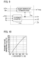
- FIG. 10 is a characteristic graph for explaining the relationship between the temperature of a permanent magnet and the ⁇ -axis current I ⁇ at predetermined conditions of the total armature-interlinked magnetic flux command ⁇ * and the ⁇ -axis current command I ⁇ *;
- FIG. 11 is a set of explanatory charts representing the difference between a vector chart at the reference condition and a vector chart at a time when demagnetization is caused under given conditions of the total armature-interlinked magnetic flux command ⁇ * and the ⁇ -axis current command I ⁇ *, in a vector chart of a synchronous machine having a magnetic-field permanent magnet;
- FIG. 12 is a system configuration diagram illustrating a synchronous machine control apparatus according to Embodiment 3 of the present invention, along with a synchronous machine;
- FIG. 13 is a system configuration diagram illustrating a variant example of synchronous machine control apparatus according to Embodiment 3 of the present invention, along with a synchronous machine;
- FIG. 14 is a configuration diagram illustrating an example of control command creation apparatus in FIG. 13 ;
- FIG. 15 is a conceptual chart for explaining the relationship between the ⁇ -axis current command I ⁇ * and the magnetic flux command ⁇ * in the magnetic flux command creation device in FIG. 14 ;
- FIG. 16 is a block diagram illustrating another configuration example of control command creation apparatus in FIG. 13 ;
- FIG. 17 is a conceptual chart for explaining the relationship between the torque command ⁇ 0 * and the magnetic flux command ⁇ * in the magnetic flux command creation device in FIG. 16 ;
- FIG. 18 is a set of configuration charts representing an example of the configuration of a magnet temperature estimation device in a synchronous machine control apparatus according to Embodiment 4 of the present invention.
- FIG. 19 is a set of configuration charts representing another example of magnet temperature estimation device in a synchronous machine control apparatus according to Embodiment 4 of the present invention.
- FIG. 20 is an explanatory chart representing an example in which there is shown a control command condition for providing a map or an equation representing the correlation between the ⁇ - ⁇ axis current and the permanent magnet temperature (magnetic flux) in a magnetic condition reference unit of a synchronous machine control apparatus according to Embodiment 4 of the present invention;
- FIG. 21 is an explanatory chart representing a speed zone for estimating the permanent magnet temperature (magnetic flux) in a synchronous machine control apparatus according to Embodiment 4 of the present invention.
- FIG. 22 is a vector chart at a time when a synchronous machine having a magnetic-field permanent magnet is not energized, in a synchronous machine control apparatus according to Embodiment 5 of the present invention.
- FIG. 23 is a set of vector charts at a time when the ⁇ -axis current is controlled to be zero, in a synchronous machine control apparatus according to Embodiment 6 of the present invention.
- FIG. 24 is a timing chart representing an example of operation timing for estimating the ⁇ -axis current command I ⁇ * or the torque command ⁇ * and the permanent magnet temperature or the magnetic flux in a synchronous machine control apparatus according to Embodiment 6 of the present invention.
- FIG. 1 is a system configuration diagram illustrating a synchronous machine control apparatus according to Embodiment 1 of the present invention, along with a synchronous machine.
- a synchronous machine 1 according to the present invention has a magnetic-field permanent magnet.
- the synchronous machine control apparatus is provided with an electric-power conversion unit 2 whose input and output are connected with a power source 12 and the armature winding of the synchronous machine 1 , respectively, a current detection unit 3 that detects the armature current of the synchronous machine 1 , a voltage command calculation unit 4 , a position detection unit 5 , a magnetic flux estimation device 6 , a magnet condition estimation unit 7 , a first coordinate converter 11 a , and a second coordinate converter 11 b.
- an electric-power conversion unit 2 whose input and output are connected with a power source 12 and the armature winding of the synchronous machine 1 , respectively, a current detection unit 3 that detects the armature current of the synchronous machine 1 , a voltage command calculation unit 4 , a position detection unit 5 , a magnetic flux estimation device 6 , a magnet condition estimation unit 7 , a first coordinate converter 11 a , and a second coordinate converter 11 b.
- the power source 12 is formed of a power supply unit or a battery that outputs a DC voltage.
- the concept of the power source 12 includes an apparatus that obtains a DC voltage from a single-phase or a three-phase AC power source by use of a well-known converter.
- the electric-power conversion unit 2 includes an inverter controlled through a well-known PWM (Pulse Width Modulation) method, converts DC electric power supplied from the power source 12 connected with the input thereof into multi-phase AC electric power, and then supplies the multi-phase AC electric power to the armature winding of the synchronous machine 1 .
- PWM Pulse Width Modulation
- the electric-power conversion unit 2 generates a multi-phase AC voltage based on a voltage command obtained from the voltage command calculation unit 4 , described later, or to be exact, based on a multi-phase AC voltage command obtained by applying coordinate transformation to a voltage command outputted from the voltage command calculation unit 4 , and applies the multi-phase AC voltage to the armature winding of the synchronous machine 1 so as to drive the synchronous machine 1 .
- an output current is produced in the armature winding of the synchronous machine 1 .
- the output current produced in the armature winding will be expressed as an “armature current”.
- the armature current which is the output current of the synchronous machine 1 , is detected by the current detection unit 3 formed of a current sensor or the like.
- the current detection unit 3 may be formed by use of a well-known technology in which the armature current is detected from a DC link current that flows from the power source 12 to the electric-power conversion unit 2 , instead of being formed of a current sensor or the like that directly detects the armature current of each phase of the synchronous machine 1 .
- the position detection unit 5 is formed of a well-known resolver, encoder, or the like, and detects the position ⁇ of the armature of the synchronous machine 1 .
- the position ⁇ of the armature of the synchronous machine 1 denotes the N-pole-direction angle, of a permanent magnet that forms the magnetic field, with respect to an axis that is set by regarding the armature winding of u-phase as a reference; in general, the d axis of a rotating biaxial coordinate system (expressed as “d-q axis, hereinafter) that rotates at the rotation speed (electric angular frequency ⁇ ) of the synchronous machine 1 is set along the N-pole direction of the foregoing permanent magnet, and the q axis thereof is set along a perpendicular direction that is advanced from the d axis by 90°.
- d-q axis rotating biaxial coordinate system
- FIG. 2 is a system configuration diagram illustrating a variant example of synchronous machine control apparatus according to Embodiment 1 of the present invention, along with a synchronous machine.
- the foregoing position detection unit 5 in FIG. 1 is utilized in the case where the position ⁇ of the armature of the synchronous machine 1 is detected by use of a well-known resolver or encoder; however, a synchronous machine control apparatus illustrated in FIG. 2 is provided with a position detection unit 5 a that utilizes a suitable well-known observer or the like and estimates the rotor position ⁇ through a calculation, based on a voltage command, an armature current, and the like.
- the configuration of the position detection unit 5 a can be implemented by the configuration described in Patent Document 5 or 6; therefore, the explanation therefor will be omitted in Embodiment 1.
- the difference between FIG. 1 and FIG. 2 lies on which one of the position detection units 5 and 5 a is provided; the other configurations are identical to each other.
- the coordinate converter 11 a converts the armature currents iu, iv, and iw of the synchronous machine 1 into currents Id and Iq on the d-q axis through a calculation according to the equation (1) below, based on the rotor position ⁇ .
- the voltage command calculation unit 4 outputs voltage commands Vd* and Vq* on the d-q axis so as to make the currents Id and Iq on the d-q axis coincide with desired control commands (current commands Id* and Iq*, in Embodiment 1).
- desired control commands current commands Id* and Iq*, in Embodiment 1.
- the voltage command calculation unit 4 performs a proportional-integral control (PI control) according to the equation (2) below so as to create the voltage commands (current feedback control commands) Vd* and Vq* on the d-q axis.
- PI control proportional-integral control
- Vd * ( Kpd + Kid s ) ⁇ ( Id * - Id )
- Vq * ( Kpq + Kiq s ) ⁇ ( Iq * - Iq ) ( 2 )
- Kpd is a current control d-axis proportional gain
- Kid is a current control d-axis integral gain
- Kpq is a current control q-axis proportional gain
- Kiq is a current control q-axis integral gain
- s is a Laplace operator.
- the reciprocal of the Laplace operator s denotes one-time time integration.
- the ratio of the carrier frequency of the electric-power conversion unit 2 such as a well-known PWM-control inverter to the rotation speed (electric angular frequency) ⁇ of the synchronous machine 1 is small, i.e., when the number of switching actions by the switching device in the electric-power conversion unit 2 in one cycle of an AC voltage applied to each phase of the synchronous machine 1 becomes small, the voltage command required for making the current of the synchronous machine 1 follow a desired current command cannot be updated, whereby it becomes difficult to perform current feedback control. In such a case, it is only necessary to perform voltage feed-forward control.
- the rotation speed ⁇ can be obtained by performing a differential operation by use of the rotor position ⁇ detected by the position detection unit 5 or 5 a.
- Vd* and Vq* are created through the equation (3) below, based on the current commands Id* and Iq* on the d-q axis, the rotation speed ⁇ , and the permanent-magnet magnetic flux ⁇ m.
- the permanent-magnet magnetic flux ⁇ m in the equation (3) is set to a predetermined value such as a reference value and then is recursively and sequentially updated with a permanent-magnet magnetic flux estimation value ⁇ mag, as a new ⁇ m, that can be obtained by putting the synchronous machine control apparatus according to Embodiment 1 of the present invention into effect.
- the voltage commands Vd* and Vq* on the d-q axis outputted from the voltage command calculation unit 4 are converted by the coordinate converter 11 b into the voltage commands vu*, vv*, and vw*, through the equation (4) below and based on the rotor position ⁇ , and are outputted to the electric-power conversion unit 2 .
- the coordinate conversion is performed with a phase obtained by correcting the rotor position ⁇ by a phase correction amount ⁇ d 1 based on the control calculation delay time.
- the electric-power conversion unit 2 applies the voltages vu, vv, vw to the synchronous machine 1 based on the voltage commands vu*, vv* and vw*, through a well-known PWM control method or the like.
- the magnetic flux estimation device 6 estimates the ⁇ axis in which a total armature-interlinked magnetic flux ⁇ is produced, based at least the voltage commands Vd* and Vq* on the d-q axis; specifically, the magnetic flux estimation device 6 estimates the angle ⁇ 0 between the d axis and the direction of the estimated total armature-interlinked magnetic flux ⁇ .
- the total armature-interlinked magnetic flux ⁇ denotes the combined magnetic field of magnetic flux (referred to as permanent-magnet magnetic flux, hereinafter) ⁇ m produced by the foregoing permanent magnet and magnetic flux (armature reaction magnetic flux) ⁇ a produced by the foregoing armature current; in Embodiment 1 of the present invention, the direction that is perpendicular to (90° advanced from) the foregoing ⁇ axis will be referred to as ⁇ axis.
- FIG. 3 is a vector chart of a synchronous machine having a magnetic-field permanent magnet; the relationship between the ⁇ - ⁇ axis and the angle ⁇ 0 between the d axis and the direction of the total armature-interlinked magnetic flux ⁇ and the like are represented.
- equation (5) which is a set of equations representing the relationship between the current Id on the d-q axis and the d-axis component ⁇ d of the total armature-interlinked magnetic flux ⁇ and the relationship between the current Iq on the d-q axis and the q-axis component ⁇ q of the total armature-interlinked magnetic flux ⁇ , ⁇ d and ⁇ q are obtained, and then the angle ⁇ 0 is calculated from the obtained ⁇ d and ⁇ q, based on the equation (6) below.
- the values of the d-q axis inductances Ld and Lq utilized in the calculation based on the equation (5) change depending on the armature current; it may be allowed that for example, the relationships between the current Id on the d-q axis and the d-q axis inductance Ld and the relationships between the current Iq on the d-q axis and the d-q axis inductance Lq are stored as equations or in a table and are changed in accordance with the current so that the error in estimating the magnetic flux due to the change in the inductance can be reduced.
- the permanent-magnet magnetic flux ⁇ m changes as the temperature changes; thus, at a time when drive is started, the permanent-magnet magnetic flux ⁇ m is set to a predetermined value such as a reference value and then is recursively and sequentially updated with a permanent-magnet magnetic flux estimation value ⁇ mag, as a new ⁇ m, that can be obtained by putting the synchronous machine control apparatus according to Embodiment 1 of the present invention into effect.
- equation (7) is a set of equations representing the relationship between the voltage Vd on the d-q axis and the d-axis component ⁇ d of the total armature-interlinked magnetic flux ⁇ and the relationship between the voltage Vq on the d-q axis and the q-axis component ⁇ q of the total armature-interlinked magnetic flux ⁇ , ⁇ d and ⁇ q are obtained, and then the angle ⁇ 0 is calculated from the obtained ⁇ d and ⁇ q, based on the foregoing equation (6).
- the initial value of the d-axis component ⁇ d of the total armature-interlinked magnetic flux ⁇ at a time when the drive of the synchronous machine 1 is started is set to a predetermined permanent-magnet magnetic flux ⁇ m such as a reference value.
- the rotation speed ⁇ is obtained by performing a differential operation by use of the rotor position ⁇ detected by the position detection unit 5 or 5 a .
- the term including the Laplace operator s is neglected.
- the resistance R As far as the resistance R is concerned, because the resistance value changes depending on the temperature of the synchronous machine 1 , it may be allowed to correct the value of the resistance R by detecting the temperature of the synchronous machine 1 ; furthermore, in the case where the terms related to the resistance R are smaller than the other terms, it may be allowed that the terms including the resistance R are neglected and information on the armature current of the synchronous machine 1 is not utilized in the calculation of the angle ⁇ 0 so that the calculation is simplified.
- FIG. 4 is a system configuration diagram illustrating an example of configuration of a magnet condition estimation unit in a synchronous machine control apparatus according to Embodiment 1 of the present invention.
- the magnet condition estimation unit 7 which is one of the features of the synchronous machine control apparatus according to Embodiment 1 of the present invention, is configured with a coordinate converter 11 c and a magnet temperature estimation device 71 and outputs a permanent magnet temperature estimation value Tmag based on currents I ⁇ and I ⁇ on the ⁇ - ⁇ axis, when predetermined control commands (in Embodiment 1, predetermined d-q axis current commands Id* and Iq*) are given thereto.
- the coordinate converter 11 c converts the armature currents Id and Iq on the d-q axis into the currents I ⁇ and I ⁇ on the ⁇ - ⁇ axis, based on the angle ⁇ 0 obtained by the magnetic flux estimation device 6 . It may be allowed that instead of the currents Id and Iq on the d-q axis, the current commands Id* and Iq* on the d-q axis are converted into the currents I ⁇ and I ⁇ on the ⁇ - ⁇ axis.
- the ⁇ -axis current I ⁇ and the ⁇ -axis current I ⁇ obtained through the conversion based on the equation (8) correspond to the magnetization current for operating the total armature-interlinked magnetic flux ⁇ of the synchronous machine 1 and to the torque current that contributes to production of the torque of the synchronous machine 1 , respectively.
- the magnet temperature estimation device 71 preliminarily stores a map or an equation indicating the relationship between the currents I ⁇ and I ⁇ on the ⁇ - ⁇ axis and the permanent-magnet temperature (estimation value) Tmag, which is caused by a temperature change at a time when predetermined d-q axis current commands Id* and Iq* are given; when I ⁇ or I ⁇ is inputted thereto, the magnet temperature estimation device 71 refers to the map or the equation and outputs the permanent-magnet temperature estimation value Tmag.
- the foregoing map or equation is preliminarily obtained by use of characteristic data on the synchronous machine 1 , when the characteristics (such as an inductance change and a magnetic demagnetization characteristic) of the synchronous machine 1 are known through an analysis or the like; when not known, it is only necessary to obtain the characteristic data through an actual measurement.
- FIG. 5 is a set of characteristic graphs for explaining the relationship between the permanent-magnet temperature and the current I ⁇ or I ⁇ on the ⁇ - ⁇ axis under a predetermined d-q axis current command condition; there is represented an example of the relationship between the permanent-magnet temperature and the current I ⁇ or I ⁇ on the ⁇ - ⁇ axis under a predetermined d-q axis current command condition (for example, Id*:0 [A], Iq*:600 [A]).
- FIG. 5(A) in which the abscissa denotes the ⁇ -axis current I ⁇ and the ordinate denotes the permanent-magnet temperature (estimation value) Tmag, represents the characteristic of the permanent-magnet temperature Tmag vs.
- FIG. 5(B) in which the abscissa denotes the ⁇ -axis current I ⁇ and the ordinate denotes the permanent-magnet temperature (estimation value) Tmag, represents the characteristic of the permanent-magnet temperature Tmag vs. the ⁇ -axis current I ⁇ .
- the permanent-magnet temperature Tmag can be estimated by setting the d-q axis current commands, for example, Id* to 0 [A] and Iq* to 600 [A] and driving the synchronous machine 1 .
- the output of the magnet condition estimation unit 7 is the permanent-magnet temperature estimation value Tmag; however, because there exists a correlation between the permanent-magnet temperature estimation value Tmag and the permanent-magnet magnetic flux estimation value (mag, the output of the magnet condition estimation unit 7 can be replaced by the permanent-magnet magnetic flux estimation value (mag, by preliminarily obtaining the correlation.
- FIG. 6 is a set of explanatory charts representing the difference between a vector chart at the reference condition and a vector chart at a time when demagnetization is caused under a given condition of the d-q axis current command, in a vector chart of a synchronous machine having a magnetic-field permanent magnet;
- FIG. 6(A) is a vector chart at a time when the permanent magnet is in the reference condition, i.e., no demagnetization is caused in the permanent magnet;
- FIG. 6(B) is a vector chart at a time when FIG. 6(A) is utilized as a reference, the permanent magnet is in a steady state where control commands, i.e., the predetermined d-q axis current commands Id* and Iq* in Embodiment 1, are constant (under the assumption that the desired control is being performed, the d-q axis currents Id and Iq are also constant), and demagnetization (decrease in the magnetic flux corresponding to ⁇ mag) of the permanent magnet is caused due to a temperature rise in the synchronous machine 1 .
- control commands i.e., the predetermined d-q axis current commands Id* and Iq* in Embodiment 1
- demagnetization decrease in the magnetic flux corresponding to ⁇ mag
- demagnetization changes the direction of the total armature-interlinked magnetic flux ⁇ , i.e., the direction of the ⁇ -axis; therefore, in the case where coordinate conversion is applied to the d-q axis currents Id and Iq, there occurs a change between the pre-demagnetization ⁇ - ⁇ axis currents I ⁇ and I ⁇ and the post-demagnetization ⁇ - ⁇ axis currents I ⁇ and I ⁇ , even when the d-q axis currents Id and Iq are kept constant; thus, by grasping the change in the ⁇ - ⁇ axis currents I ⁇ and I ⁇ , a change in the permanent-magnet magnetic flux ⁇ mag, i.e., a change in the permanent-magnet temperature Tmag can also be grasped.
- the permanent-magnet temperature (or magnetic flux) of the synchronous machine 1 is estimated based on not voltage information but the ⁇ - ⁇ axis currents I ⁇ and I ⁇ ; therefore, the voltage-output accuracy (e.g., a voltage error caused by the dead time of the inverter) of the electric-power conversion unit 2 hardly provides an adverse effect, whereby there is demonstrated an effect that the temperature or the magnetic flux of the permanent magnet can accurately be estimated.
- the voltage-output accuracy e.g., a voltage error caused by the dead time of the inverter
- FIG. 7 is a system configuration diagram illustrating a synchronous machine control apparatus according to Embodiment 2 of the present invention, along with a synchronous machine.
- the control commands the d-q axis current commands Id* and Iq* are given; however, in Embodiment 2, as the control commands, the total armature-interlinked magnetic flux command ⁇ * and the ⁇ -axis current command I ⁇ * are given.
- the position detection unit 5 that obtains the rotor position ⁇ through an estimation calculation.
- the magnetic flux estimation device 6 a estimates the angle ⁇ 0 between the d axis and the direction of the estimated total armature-interlinked magnetic flux ⁇ , described in Embodiment 1, and obtains the angle ⁇ (hereinafter, expressed as the phase of the total armature-interlinked magnetic flux ⁇ ) between the direction of the estimated total armature-interlinked magnetic flux ⁇ and an axis established by taking the magnitude
- the d-axis component ⁇ d and the q-axis component ⁇ q of the total armature-interlinked magnetic flux ⁇ are estimated, and then the magnitude
- ⁇ ⁇ ⁇ ⁇ ⁇ ⁇ d 2 + ⁇ ⁇ ⁇ q 2 ( 10 )
- FIG. 8 is a system diagram illustrating an example of configuration of a voltage command calculation unit in a synchronous machine control apparatus according to Embodiment 2 of the present invention.
- the voltage command calculation unit 4 a is configured with a ⁇ -axis current command creation device 41 and a ⁇ - ⁇ axis voltage command creation device 42 , and outputs ⁇ - ⁇ axis voltage commands V ⁇ * and V ⁇ * in such a way that the total armature-interlinked magnetic flux (and the ⁇ -axis current I ⁇ coincide with desired control commands, i.e., the total armature-interlinked magnetic flux command ⁇ * and ⁇ -axis current command I ⁇ *, respectively.
- the ⁇ -axis current command creation device 41 Based on a magnetic-flux error ⁇ , the ⁇ -axis current command creation device 41 creates a ⁇ -axis current command I ⁇ * in such a way that the total armature-interlinked magnetic flux error ⁇ is adjusted to be zero.
- the magnetic-flux error ⁇ is calculated by subtracting the magnitude
- of the total armature-interlinked magnetic flux ⁇ , which has been obtained through the equation (10), from the total armature-interlinked magnetic flux command ⁇ *; the equation (12) below is the arithmetic expression therefor. ⁇ ⁇ * ⁇
- the ⁇ -axis current I ⁇ is a magnetization current, which is the magnetization component for the synchronous machine 1
- the total armature-interlinked magnetic flux can be operated by the ⁇ -axis current.
- the increase/decrease amount of the magnetization current and the increase/decrease amount of the total armature-interlinked magnetic flux are in proportion to each other with the ⁇ -axis direction inductance L ⁇ as the proportionality coefficient; as the controller for adjusting the magnetic-flux error ⁇ to be zero, for example, an integrator is suitable.
- I ⁇ ⁇ ⁇ * Kf ⁇ ⁇ ⁇ ⁇ ⁇ s ( 13 ) where Kf is an integration gain.
- the ⁇ - ⁇ axis voltage commands V ⁇ * and V ⁇ * are outputted in such a way that the ⁇ - ⁇ axis currents I ⁇ and I ⁇ coincide with the current commands I ⁇ * and I ⁇ *, respectively.
- the ⁇ - ⁇ axis currents I ⁇ and I ⁇ are obtained by a magnet condition estimation unit 7 a , described later.
- PI control proportional-integral control
- V ⁇ ⁇ ⁇ * ( K ⁇ ⁇ p ⁇ ⁇ ⁇ + Ki ⁇ ⁇ ⁇ s ) ⁇ ( I ⁇ ⁇ ⁇ * - I ⁇ ⁇ ⁇ )
- V ⁇ ⁇ ⁇ * ( Kp ⁇ ⁇ ⁇ + Ki ⁇ ⁇ ⁇ s ) ⁇ ( I ⁇ ⁇ ⁇ * - I ⁇ ⁇ ⁇ ) ( 14 )
- Kp ⁇ is a current control ⁇ -axis proportional gain
- Ki ⁇ is a current control ⁇ -axis integral gain
- Kp ⁇ is a current control ⁇ -axis proportional gain
- Ki ⁇ is a current control ⁇ -axis integral gain
- Ki ⁇ is a current control ⁇ -axis integral gain
- voltage feed-forward control may be performed, as is the case with Embodiment 1.
- V ⁇ * and V ⁇ * are created through the equation (15) below, based on the current commands I ⁇ * and I ⁇ * on the ⁇ - ⁇ axis, the rotation speed ⁇ , and the amplitude
- V ⁇ ⁇ ⁇ * R ⁇ I ⁇ ⁇ ⁇ *
- V ⁇ ⁇ ⁇ * R ⁇ I ⁇ ⁇ ⁇ * + ⁇ ⁇ ⁇ ⁇ ⁇ ( 15 )
- all the ⁇ - ⁇ axis currents utilized in the calculation are I ⁇ * and I ⁇ *; however, instead of these currents, the currents I ⁇ and I ⁇ on the ⁇ - ⁇ axis, or the average value of I ⁇ * and I ⁇ and the average value of I ⁇ * and I ⁇ may be utilized. It may be allowed that in the normal mode, only current feedback control is performed or both current feedback control and voltage feed-forward control are performed, and under a driving condition where current feedback control is difficult to perform, current feedback control is negated and only voltage feed-forward control is performed.
- the voltage commands V ⁇ * and V ⁇ on the ⁇ - ⁇ axis outputted from the voltage command calculation unit 4 a are converted by the coordinate converter 11 d into the voltage commands vu*, vv*, and vw*, through the equation (16) below and based on the phase ⁇ , of the total armature-interlinked magnetic flux ⁇ , that has been estimated by the magnetic flux estimation device 6 a , and are outputted to the electric-power conversion unit 2 .
- the coordinate conversion is performed with a phase obtained by correcting the rotor position ⁇ by a phase correction amount ⁇ d 2 based on the control calculation delay time.
- the electric-power conversion unit 2 applies the voltages vu, vv, vw to the synchronous machine 1 based on the voltage commands vu*, vv* and vw*, through a well-known PWM control method or the like.
- FIG. 9 is a configuration diagram illustrating an example of configuration of a magnet condition estimation unit in a synchronous machine control apparatus according to Embodiment 2 of the present invention.
- the magnet condition estimation unit 7 a is configured with the coordinate converter 11 c and the magnet temperature estimation device 71 a and outputs the permanent-magnet temperature estimation value Tmag based on the ⁇ -axis current I ⁇ , when predetermined control commands (in Embodiment 2, the total armature-interlinked magnetic flux command ⁇ * and the ⁇ -axis current command I ⁇ *) are given thereto.
- the coordinate converter 11 c converts the currents Id and Iq on the d-q axis into the currents I ⁇ and I ⁇ on the ⁇ - ⁇ axis, based on the angle ⁇ 0 obtained by the magnetic flux estimation device 6 a .
- the values of the currents I ⁇ and I ⁇ on the ⁇ - ⁇ axis, created by the coordinate converter 11 c , are utilized also in the voltage command calculation unit 4 a.
- the magnet temperature estimation device 71 a preliminarily stores a map or an equation indicating the relationship between the ⁇ -axis current I ⁇ and the permanent-magnet temperature (estimation value) Tmag, which is caused by a temperature change at a time when predetermined total armature-interlinked magnetic flux command ⁇ * and the ⁇ -axis current command I ⁇ * are given; when the ⁇ -axis I ⁇ is inputted thereto, the magnet temperature estimation device 71 a refers to the map or the equation and outputs the permanent-magnet temperature estimation value Tmag.
- the foregoing map or equation is preliminarily obtained by use of characteristic data on the synchronous machine 1 , when the characteristics (such as an inductance change and a magnetic demagnetization characteristic) of the synchronous machine 1 are known through an analysis or the like; when not known, it is only necessary to obtain the characteristic data through an actual measurement.
- the current command I ⁇ * outputted from the ⁇ -axis current command creation device 41 may be utilized.
- FIG. 10 is a characteristic graph for explaining the relationship between the permanent-magnet temperature Tmag and the ⁇ -axis current I ⁇ at predetermined conditions of the total armature-interlinked magnetic flux command ⁇ * and the ⁇ -axis current command I ⁇ *; as an example, there is represented the relationship between the permanent-magnet temperature Tmag and the ⁇ -axis current I ⁇ under the condition that the total armature-interlinked magnetic flux command ⁇ * and the ⁇ -axis current command I ⁇ * are set to 0.08 [Wb] and 450 [A], respectively.
- FIG. 10 is a characteristic graph for explaining the relationship between the permanent-magnet temperature Tmag and the ⁇ -axis current I ⁇ at predetermined conditions of the total armature-interlinked magnetic flux command ⁇ * and the ⁇ -axis current command I ⁇ *; as an example, there is represented the relationship between the permanent-magnet temperature Tmag and the ⁇ -axis current I ⁇ under the condition that the total armature-interlinked magnetic flux command ⁇ * and the ⁇ -
- the permanent-magnet temperature Tmag can be estimated based on the ⁇ -axis current I ⁇ .
- the configuration illustrated in FIG. 10 for example, by setting the total armature-interlinked magnetic flux command ⁇ * and the ⁇ -axis current command I ⁇ * to set to 0.08 [Wb] and 450 [A], respectively, so as to drive the synchronous machine 1 , the permanent-magnet temperature Tmag can be estimated based on the ⁇ -axis current I ⁇ .
- the output of the magnet condition estimation unit 7 a is the permanent-magnet temperature estimation value Tmag; however, because as described above, there exists a correlation between the permanent-magnet temperature estimation value Tmag and the permanent-magnet magnetic flux estimation value ⁇ mag, the output of the magnet condition estimation unit 7 a can be replaced by the permanent-magnet magnetic flux estimation value ⁇ mag, by preliminarily obtaining the correlation.
- FIG. 11 is a set of explanatory charts representing the difference between a vector chart at the reference condition and a vector chart at a time when demagnetization is caused under given conditions of the total armature-interlinked magnetic flux command ⁇ * and the ⁇ -axis current command I ⁇ *, in a vector chart of a synchronous machine having a magnetic-field permanent magnet.
- FIG. 11 FIG. 11 , FIG.
- FIG. 11(A) is a vector chart at a time when the permanent magnet is in the reference condition, i.e., no demagnetization is caused in the permanent magnet;
- FIG. 6(B) is a vector chart at a time when the magnetic flux decreases by an amount corresponding to demagnetization of the permanent magnet, caused due to a temperature rise in the synchronous machine 1 , i.e., by ⁇ mag, when the permanent magnet is in a steady state where the magnitude
- the foregoing demagnetization of the permanent magnet changes the direction of the total armature-interlinked magnetic flux ⁇ , i.e., the direction of the ⁇ -axis; therefore, there occurs a change between the pre-demagnetization ⁇ -axis current I ⁇ and the post-demagnetization ⁇ -axis current I ⁇ , even when the total armature-interlinked magnetic flux command ⁇ * and the ⁇ -axis current command I ⁇ * are kept constant; thus, by grasping the change in the ⁇ -axis current I ⁇ , a change in the permanent-magnet magnetic flux ⁇ mag, i.e., a change in the permanent-magnet temperature Tmag can also be grasped.
- Embodiment 2 of the present invention As is the case with Embodiment 1, it is not required to mount a temperature detector directly on the permanent magnet, and the permanent-magnet temperature (or magnetic flux) of the synchronous machine 1 is estimated based on not voltage information but the ⁇ -axis current I ⁇ ; therefore, the voltage-output accuracy, for example, a voltage error caused by the dead time of the inverter, of the electric-power conversion unit 2 hardly provides an adverse effect, whereby there is demonstrated an effect that the temperature or the magnetic flux of the permanent magnet can accurately be estimated. When there exists at least one kind of map data, these values can be estimated; thus, there is demonstrated an effect that the permanent-magnet temperature or magnetic flux can be estimated with less map data.
- FIG. 12 is a system configuration diagram illustrating a synchronous machine control apparatus according to Embodiment 3 of the present invention, along with a synchronous machine
- FIG. 13 is a system configuration diagram illustrating a variant example of synchronous machine control apparatus according to Embodiment 3 of the present invention, along with a synchronous machine. As illustrated in each of FIGS.
- control command calculation unit 8 which is a higher-hierarchy command creation system for creating the control commands based on the torque command so that the torque command is limited in accordance with the ⁇ -axis current I ⁇ and the control commands are outputted in accordance with the limited torque command.
- the control command calculation unit 8 generates the d-q axis current command Id* and Iq*, as the control commands explained in Embodiment 1; in contrast, in FIG. 13 , the control command calculation unit 8 a generates the total armature-interlinked magnetic flux command ⁇ * and the ⁇ -axis current command I ⁇ *, as the control commands explained in Embodiment 2.
- the control command calculation unit 8 ( 8 a ) is configured with a torque command limitation device 81 and a control command creation device 82 ( 82 a ).
- the configurations of the torque command limitation devices 81 in FIGS. 12 and 13 are the same as each other.
- the torque command to be limited by the torque command limitation device 81 and the (limited) torque command, the output of the torque command limitation device 81 are distinguished from each other, by letting ⁇ * denote the former and letting ⁇ 0 * denote the latter.
- the ⁇ -axis current I ⁇ corresponds to the magnetization current for operating the total armature-interlinked magnetic flux of the synchronous machine 1 ; when due to a temperature rise in the synchronous machine 1 , demagnetization (decrease in the magnetic flux, corresponding to ⁇ mag) of the permanent magnet is caused, an increase in the ⁇ -axis current I ⁇ compensates the magnetic flux corresponding to the demagnetization (there exists an exception in the case where as the control commands, the d-q axis current commands Id* and Iq* are given).
- the armature current (effective value) of the synchronous machine 1 also increases; thus, due to the heat (such as the heat produced in the resistance of the armature winding) produced in the synchronous machine 1 , the temperature of the overall synchronous machine 1 including the permanent magnet also increases, whereby demagnetization of the permanent magnet is facilitated. Furthermore, when the allowable temperature is exceeded, irreversible demagnetization may be caused in which even when the temperature falls down to the normal temperature, the magnetic flux does not return to the state at a time before the demagnetization is caused.
- an upper limit value of the armature current, of the synchronous machine 1 that is limited by the performance (e.g., the device rating of the switching device, which is a constituent element of the electric-power conversion unit 2 ) of the electric-power conversion unit 2 ; it is possible that due to the increase in the ⁇ -axis current I ⁇ , the upper limit value is exceeded.
- the torque command ⁇ * is limited in accordance with the ⁇ -axis current I ⁇ so that the magnitudes of the control commands (the d-q axis current commands Id* and Iq*, or the total armature-interlinked magnetic flux command ⁇ * and the ⁇ -axis current command I ⁇ *) are indirectly reduced and hence the armature current (effective value) is suppressed from increasing.
- the torque command limitation device 81 limits the torque command ⁇ * in accordance with the ⁇ -axis current I ⁇ and outputs the (limited) torque command ⁇ 0 *.
- the correlation between the ⁇ -axis current I ⁇ and the torque command ⁇ * is set in accordance with the driving condition, the heat capacity of the synchronous machine 1 or cooling performance thereof, and the performance of the electric-power conversion unit 2 .
- the ⁇ -axis current I ⁇ exceeds a given value, it is determined that the permanent-magnet temperature has approximated to a temperature leading to irreversible demagnetization, and then, the torque command is decreased; extremely speaking, for example, processing of decreasing the torque command to “0” is implemented and the (limited) torque command ⁇ 0 * is outputted. It may be allowed that as the ⁇ -axis current I ⁇ increases, the limitation value of the torque command ⁇ * is reduced stepwise.
- the control command creation device 82 in FIG. 12 creates the d-q axis current commands Id* and Iq*, which are control commands.
- the synchronous machine 1 having a magnetic-field permanent magnet it is known that there exist numerous combinations, of the d-axis currents Id and the q-axis current Iq, that can produce a single and the same torque; for the (limited) torque command ⁇ 0 *, appropriate d-q axis current commands Id* and Iq* conforming to the desired conditions (e.g., the maximum efficiency, the maximum torque, and the like) are outputted.
- the methods of selecting the d-q axis current commands Id* and Iq* include a well-known method of making the efficiency of a motor maximum, a method of making the power factor of a motor “1”, a method of making the torque obtained for a given interlinked magnetic flux maximum, a method of making the torque obtained for a given motor current maximum, and the like.
- an arbitrary method may be utilized in selecting the d-q axis current commands Id* and Iq*, based on the torque command ⁇ 0 *, and hence the detail of the method of selecting these current commands Id* and Iq* will be omitted; however, as the most simple method, for example, there exists a method in which the negative d-axis current command value Id* is adjusted in such a way that the d-q axis voltage commands Vd* and Vq* outputted from the voltage command calculation unit 4 do not exceed the maximum voltage that the electric-power conversion unit 2 can apply to the synchronous machine 1 , and then the q-axis current command Iq* is created based on the equation (17).
- the permanent-magnet magnetic flux ⁇ m in the equation (17) below changes as the temperature changes; thus, at a time when drive is started, the permanent-magnet magnetic flux ⁇ m is set to a predetermined value such as a reference value and then is recursively and sequentially updated with a permanent-magnet magnetic flux estimation value ⁇ mag that can be obtained by performing the magnet temperature (magnetic flux) estimation.
- Iq * ⁇ 0 * Pm ⁇ ⁇ ⁇ ⁇ ⁇ m + ( Ld - Lq ) ⁇ Id * ⁇ ( 17 ) where Pm is the number of pole pairs in the synchronous machine 1 .
- FIG. 13 illustrating a variant example of the synchronous machine control apparatus according to Embodiment 3, based on the (limited) torque command ⁇ 0 *, the control command creation device 82 a creates the total armature-interlinked magnetic flux command ⁇ * and the ⁇ -axis current command I ⁇ *, which are control commands.
- the control command creation device 82 a outputs the total armature-interlinked magnetic flux command ⁇ * and ⁇ -axis current command I ⁇ *, which are appropriate control commands conforming to the desired conditions (e.g., the maximum efficiency, the maximum torque, and the like).
- FIG. 14 is a diagram illustrating an example of the control command creation apparatus in FIG. 13 .
- the control command creation device 82 a is configured with a ⁇ -axis current command creation device 83 and a magnetic flux command creation device 84 ; in order to make the control command creation device 82 a more suitable, there is added a ⁇ -axis current command limitation device 85 that limits the ⁇ -axis current command I ⁇ * by use of ⁇ -axis current command I ⁇ * (indicated by the dotted-line arrow in FIG. 14 ) calculated by the voltage command calculation unit 4 a.
- the ⁇ -axis current command creation device 83 calculates the ⁇ -axis current command I ⁇ *, through the equation (18) below.
- of the total armature-interlinked magnetic flux obtained through the equation (10) below may be utilized, instead of the total armature-interlinked magnetic flux command ⁇ *, in the calculation according to the equation (18).
- the ⁇ -axis current command I ⁇ * is limited based on a current limitation value Imax, which is determined based on the specification or the like of the electric-power conversion unit 2 , and the ⁇ -axis current command I ⁇ * in such a way that the synthetic electric current of the ⁇ -axis current command I ⁇ * and the ⁇ -axis current command I ⁇ * is limited to the current limitation value Imax.
- the upper limit value I ⁇ *max of the ⁇ -axis current command I ⁇ * is obtained through the equation (20) below; while I ⁇ *max is sequentially obtained, the ⁇ -axis current command I ⁇ * is limited in such a way that the absolute value of the ⁇ -axis current command I ⁇ * becomes the same as or smaller than I ⁇ *max.
- I ⁇ *max ⁇ square root over (( I max) 2 ⁇ ( I ⁇ *) 2 ) ⁇ square root over (( I max) 2 ⁇ ( I ⁇ *) 2 ) ⁇ (20)
- the magnetic flux command creation device 84 In response to the inputted ⁇ -axis current command I ⁇ *, the magnetic flux command creation device 84 outputs an optimum total armature-interlinked magnetic flux command ⁇ *, for example, the total armature-interlinked magnetic flux command ⁇ * with which the maximum torque is outputted under a condition that the armature current (effective value) of the synchronous machine 1 is constant.
- FIG. 15 is a conceptual chart for explaining the relationship between the ⁇ -axis current command I ⁇ * and the magnetic flux command ⁇ * in the magnetic flux command creation device in FIG. 14 , and represents an example of the relationship between the ⁇ -axis current command I ⁇ * and the total armature-interlinked magnetic flux command ⁇ *, which satisfies the foregoing conditions; the relationship is preliminarily stored, as an equation or table data, in the magnetic flux command creation device 84 , and then an optimum total armature-interlinked magnetic flux ⁇ * is outputted in response to the inputted ⁇ -axis current command I ⁇ *.
- the ⁇ -axis current command limitation device 85 is added and the ⁇ -axis current command I ⁇ * is limited through the equation (20), the calculation performed from the ⁇ -axis current command creation device 83 to the magnetic flux command creation device 84 becomes circular.
- the foregoing processing is performed by a microcomputer with a predetermined calculation cycle, it may be required to take measures such as raising the stability of the calculation processing, for example, in such a way that as the total armature-interlinked magnetic flux command ⁇ * to be utilized by the ⁇ -axis current command creation device 83 , the immediately previous (one calculation cycle before) calculation result is utilized, and the present total armature-interlinked magnetic flux command ⁇ * is calculated based on the ⁇ -axis current command I ⁇ * calculated by use of the command value, or in such a way that the magnetic flux command creation device 84 outputs the value of the total armature-interlinked magnetic flux command ⁇ * through an appropriate filter.
- FIG. 16 is a block diagram illustrating another configuration example of the control command creation device in FIG. 13 .
- the control command creation device 82 b is configured in such a way as to create the total armature-interlinked magnetic flux command ⁇ * based not on the ⁇ -axis current command I ⁇ * but on the (limited) torque command ⁇ 0 *.
- a magnetic flux command creation device 84 a in FIG. 16 outputs an optimum total armature-interlinked magnetic flux command ⁇ * in response to the inputted (limited) torque command ⁇ 0 *.
- ⁇ * the total armature-interlinked magnetic flux command ⁇ * for the inputted (limited) torque command ⁇ 0 * can be obtained.
- ⁇ 0 * Pm ⁇ * ⁇ I ⁇ * (21)
- FIG. 17 is a conceptual chart for explaining the relationship between the torque command ⁇ 0 * and the magnetic flux command ⁇ * in the magnetic flux command creation device in FIG. 16 , and represents an example of the relationship, between the (limited) torque command ⁇ 0 * and the total armature-interlinked magnetic flux command ⁇ *, that is obtained based on FIG. 15 .
- the magnetic flux command creation device 84 b preliminarily stores the relationship, as an equation or table data, in the magnetic flux command creation device 84 a and then outputs an optimum total armature-interlinked magnetic flux ⁇ * in accordance with the inputted torque command ⁇ 0 *.
- the operations of the ⁇ -axis current command creation device 83 and the ⁇ -axis current command limitation device 85 in the control command creation device 82 b are the same as those in the control command creation device 82 a.
- the electric-power conversion unit 2 there exists an output-capable voltage maximum value Vmax (converted into an effective value) that depends on the specification of the electric-power conversion unit 2 and the output voltage Vpn of the power source 12 ; it is desirable that the total armature-interlinked magnetic flux command ⁇ * is limited in such a way that the induction voltage generated in the armature of the synchronous machine 1 is suppressed to be the same as or lower than Vmax.
- the induction voltage is determined by the multiplication product of the rotation speed ⁇ of the synchronous machine 1 and the total armature-interlinked magnetic flux ⁇ , when the voltage drop across the resistance R of the synchronous machine 1 is neglected; thus, it is more appropriate that based on the output-capable voltage maximum value Vmax of the electric-power conversion unit 2 , the magnetic-flux maximum value ⁇ max corresponding to the rotation speed ⁇ of the synchronous machine 1 is sequentially calculated through the equation (22) below and the value obtained by limiting the output of the magnetic flux command creation device 84 ( 84 a ) with ⁇ max is adopted as the total armature-interlinked magnetic flux command ⁇ *.
- a synchronous machine control apparatus according to Embodiment 4 of the present invention.
- the magnet temperature estimation device 71 illustrated in FIG. 4
- the magnet temperature estimation device 71 a illustrated in FIG. 9
- the magnet temperature estimation device 71 c illustrated in the synchronous machine control apparatus according to embodiment 2
- FIG. 18 is a set of configuration charts representing an example of the configuration of a magnet temperature estimation device in a synchronous machine control apparatus according to Embodiment 4 of the present invention
- FIG. 18 represents the configuration of the magnet temperature estimation device 71 b at a time when as the control commands explained in Embodiment 1, the d-q axis current commands Id* and Iq* are given.
- FIG. 19 is a set of configuration charts representing another example of the configuration of a magnet temperature estimation device in a synchronous machine control apparatus according to Embodiment 4 of the present invention;
- FIG. 19 represents the magnet temperature estimation device 71 c at a time when as the control commands explained in Embodiment 2, the ⁇ -axis current command I ⁇ * and the total armature-interlinked magnetic flux command ⁇ * are given.
- the synchronous machine control apparatus is characterized by including, in both the magnet temperature estimation device 71 b in FIG. 18 and the magnet temperature estimation device 71 c in FIG. 19 , magnetic condition reference units (charts 72 a to 72 c in FIG. 18 and charts 72 d to 72 f in FIG. 19 ) having a map or an equation indicating the correlation between the ⁇ - ⁇ axis current and the permanent-magnet temperature (magnetic flux) for each of a plurality of combinations of control commands, i.e., d-q axis current commands Id* and Iq* or a plurality of combinations of the ⁇ -axis current command I ⁇ * and the total armature-interlinked magnetic flux command ⁇ *.
- a synchronous machine control apparatus (Id 1 , Iq 1 ), (Id 2 , Iq 2 ), (Id 3 , Iq 3 ), (Id 4 , Iq 4 ) . . .
- two or more similar magnetic condition reference units are prepared.
- the foregoing map or equation is preliminarily obtained by use of characteristic data on the synchronous machine 1 , when the characteristics (such as an inductance change and a magnetic demagnetization characteristic) of the synchronous machine 1 are known through an analysis or the like; when not known, it is only necessary to obtain the characteristic data through an actual measurement.
- the magnet temperature estimation device 71 b When the d-q axis current commands Id* and Iq* at a time when the synchronous machine 1 is being driven approximately coincide with the preliminarily prepared control command conditions in each of a plurality of magnetic condition reference units 72 (in determining of the coincidence, some margin is given), the magnet temperature estimation device 71 b outputs the permanent-magnet temperature estimation value Tmag by referring to the map or the equation of the magnetic condition reference unit 72 in which the control command conditions include the ⁇ -axis current I ⁇ or the ⁇ -axis current I ⁇ .
- two or more similar magnetic condition reference units are prepared.
- the magnet temperature estimation device 71 c When the control command (I ⁇ *, ⁇ *) at a time when the synchronous machine 1 is being driven approximately coincide with the preliminarily prepared control command conditions in each of a plurality of magnetic condition reference units 72 , the magnet temperature estimation device 71 c outputs the permanent-magnet temperature estimation value Tmag by referring to the map or the equation in the magnetic condition reference unit 72 in which the control command conditions include the ⁇ -axis current I ⁇ or the ⁇ -axis current I ⁇ .
- control commands at a time when the synchronous machine 1 is being driven do not coincide with the preliminarily prepared control command conditions in each of a plurality of magnetic condition reference units 72 , it is only necessary to perform processing in which, for example, the permanent-magnet temperature estimation operation is not implemented, and the temperature estimation value of the immediately previous temperature estimation operation is held and outputted, as the permanent-magnet temperature estimation value Tmag. In the case where such processing is performed, the permanent-magnet temperature estimation operation is implemented intermittently.
- the probability that the control commands at a time when the synchronous machine 1 is being driven coincide with the preliminarily prepared control command conditions in the magnetic condition reference units 72 rises in proportion to the number of the magnetic condition reference units; thus, although it becomes possible to frequently estimate the permanent-magnet temperature (magnetic flux) even when the control command changes, the effect of the present invention, i.e., that estimation can be performed with fewer map data pieces may be reduces.
- control command condition for providing a map or an equation representing the correlation between the ⁇ - ⁇ axis current and the permanent magnet temperature (magnetic flux) in the magnetic condition reference unit 72 may be defined with a predetermined current value or larger.
- FIG. 20 is an explanatory chart representing an example in which there is shown a control command condition for providing a map or an equation representing the correlation between the ⁇ - ⁇ axis current and the permanent magnet temperature (magnetic flux) in a magnetic condition reference unit of a synchronous machine control apparatus according to Embodiment 4 of the present invention.
- the outer dotted-line circle represents the current limitation value Imax
- the inner dotted-line circle represents the minimum current condition I 1 for estimating the permanent-magnet temperature (magnetic flux)
- the black-circle marks arranged in the area surrounded by the two circles are control command conditions for providing a map or an equation indicating the correlation between the ⁇ - ⁇ axis current and the permanent-magnet temperature (magnetic flux) in the magnetic condition reference unit 72 .
- a positive d-axis current is not frequently applied to the synchronous machine 1 having a magnetic-field permanent magnet; therefore, in order to reduce the map data, the black-circle marks are provided only in the area where the d-axis current is negative.
- FIG. 20 is nothing but an example; therefore, it is not necessarily required that as represented in FIG. 20 , the conditions represented by the foregoing black-circle marks are spaced equally from one another; in the case where when the synchronous machine 1 is driven, only specific control commands are provided, it is only necessary to set the foregoing black-circle marks in accordance with the control commands.
- the synchronous machine control apparatus is characterized by being insusceptible to the effect of the voltage output accuracy (e.g., a voltage error caused by the dead time of the inverter) of the electric-power conversion unit 2 , compared to a conventional technology, because the permanent-magnet temperature (magnetic flux) is directly estimated by use of the ⁇ - ⁇ axis currents I ⁇ and I ⁇ , instead of voltage information.
- the voltage output accuracy e.g., a voltage error caused by the dead time of the inverter
- the permanent-magnet temperature magnetic flux
- the foregoing effect is provided to the accuracy in estimating the total armature-interlinked magnetic flux and the accuracy in coordinate-converting the armature current, which undergoes the estimation accuracy, into the currents on the ⁇ axis and the ⁇ axis; thus, the voltage output accuracy may provide an effect to the accuracy in estimating the permanent-magnet temperature (magnetic flux).
- the speed in many cases, passes through a speed zone where the voltage accuracy is likely to provide an effect before the demagnetization caused by an temperature increase provides an effect; it is conceivable that in this kind of application, the necessity of estimating the permanent-magnet temperature (magnetic flux) in the low-speed zone is small.
- FIG. 21 is an explanatory chart representing a speed zone for estimating the permanent magnet temperature (magnetic flux) in a synchronous machine control apparatus according to Embodiment 4 of the present invention; in the zone (in the range from ⁇ 1 to ⁇ 1 , when the negative speed is considered) where the rotation speed is a predetermined speed ⁇ 1 or lower and the voltage accuracy may provide an effect, the permanent-magnet temperature (magnetic flux) estimation operation is not performed even when the control commands at a time the synchronous machine is being driven coincide with the preliminarily prepared control command conditions in the magnetic condition reference units 72 . In such a manner as described above, the permanent-magnet temperature (magnetic flux) estimation operation is performed only in the high-speed zone where the voltage output accuracy of the electric-power conversion unit is becomes higher; thus, there is demonstrated an effect that the estimation accuracy is raised.
- the magnetic condition reference units 72 for each of a plurality of control commands are prepared; therefore, because the probability that the control commands at a time when the synchronous machine 1 is being driven coincide with the preliminarily prepared control command conditions in the magnetic condition reference units 72 rises, there is demonstrated an effect that even when the control command sequentially changes, the change in the control command is followed and the permanent-magnet temperature (magnetic flux) can be estimated.
- control commands at a time when the synchronous machine 1 is being driven are forced to coincide, every predetermined period, with preliminarily prepared control command conditions in the magnetic condition reference units 72 so that the permanent-magnet temperature estimation operation is performed without fail in steps of a predetermined period; thus, there is demonstrated an effect that by performing the permanent-magnet temperature (magnetic flux) estimation every predetermined period, the estimation operation can be prevented from being not performed for a long time.
- the temperature (magnetic flux) is estimated only when the accuracy in estimating the total armature-interlinked magnetic flux based on the voltage command is extremely high or only when the accuracy in coordinate-converting the armature current, which undergoes the foregoing estimation accuracy, into the ⁇ -axis current and the ⁇ -axis current is extremely high; thus, there is demonstrated an effect that the estimation accuracy is raised.
- a synchronous machine control apparatus in addition to the mode in which as described in Embodiments 1 through 4, the permanent-magnet temperature (magnetic flux) is estimated based on the control commands and the ⁇ - ⁇ axis currents, there is provided a mode in which the control commands are set in such a way that the armature current of the synchronous machine 1 becomes zero and then the permanent-magnet temperature (magnetic flux) is estimated based on the total armature-interlinked magnetic flux ⁇ , which has been estimated when the armature current has been set.
- the method, described in Embodiments 1 through 4, of estimating the permanent-magnet temperature (magnetic flux) based on the ⁇ - ⁇ axis currents is a method under the assumption that some sort of current is flowing in the armature winding of the synchronous machine 1 ; therefore, when the armature current of the synchronous machine 1 is zero, the permanent-magnet temperature (magnetic flux) cannot be estimated. Accordingly, in order to estimate the permanent-magnet temperature (magnetic flux), it is required to apply an unnecessary current to the armature winding; thus, the flow of the unnecessary current may cause unnecessary torque or raise the temperature of the permanent magnet.
- FIG. 22 is a vector chart at a time when a synchronous machine having a magnetic-field permanent magnet is not energized, in a synchronous machine control apparatus according to Embodiment 5 of the present invention.
- the permanent-magnet magnetic flux ⁇ m forms magnetic flux included in the armature-interlinked magnetic flux; therefore, the total armature-interlinked magnetic flux ⁇ and the permanent-magnet magnetic flux ⁇ m coincide with each other.
- the induction voltage caused by the permanent-magnet magnetic flux ⁇ m generates the voltage across the synchronous machine 1 ; therefore, the d-q axis voltages Vd and Vq at a time when the synchronous machine is not energized are obtained through the equation (23) below.
- Vd 0
- the armature current of the synchronous machine 1 is monitored by the current detection unit 3 , while, for example, the total armature-interlinked magnetic flux command ⁇ * is set to a predetermined permanent-magnet magnetic flux value such as a reference value and the ⁇ -axis current command I ⁇ * is set to zero; the total armature-interlinked magnetic flux command ⁇ * is adjusted in such a way that the armature current becomes zero; then, the total armature-interlinked magnetic flux command ⁇ * at a time when the armature current is zero and no energization is performed corresponds to the permanent-magnet magnetic flux estimation value ⁇ mag.
- the armature current may flow in the process of adjusting the total armature-interlinked magnetic flux command ⁇ *, no unnecessary current flows in the armature winding during the estimation of the permanent-magnet magnetic flux.
- Embodiment 5 can be added to any one of Embodiments 1 through 4.
- the foregoing synchronous machine control apparatus can demonstrate an effect that the permanent-magnet temperature (magnetic flux) can be estimated even during the non-energization period in which the ⁇ - ⁇ axis currents are not generated.
- the total armature-interlinked magnetic flux command ⁇ * needs to be set in such a way as to fall within the range represented by the equation (25) below.
- FIG. 23 is a set of vector charts at a time when the ⁇ -axis current is controlled to be zero, in a synchronous machine control apparatus according to Embodiment 6 of the present invention
- FIG. 23(A) is a vector chart at a time when the permanent magnet is in the reference (unloaded) condition, i.e., no demagnetization is caused in the permanent magnet;
- FIG. 23(A) is a vector chart at a time when the permanent magnet is in the reference (unloaded) condition, i.e., no demagnetization is caused in the permanent magnet;
- 23(B) is a vector chart at a time when the magnetic flux decreases by an amount corresponding to demagnetization of the permanent magnet, caused due to a temperature rise in the synchronous machine 1 , i.e., by ⁇ mag, when the permanent magnet is in a steady state where the magnitude
- of total armature-interlinked magnetic flux and the ⁇ -axis current I ⁇ are constant under an assumption that the total armature-interlinked magnetic flux command ⁇ *( ⁇ max) and the ⁇ -axis current command I ⁇ *( 0), which are predetermined control commands, are constant, i.e., desirably controlled.
- the armature reaction magnetic flux ⁇ a is exerted to weaken the permanent-magnet magnetic flux ⁇ m; in this case, when the demagnetization of the permanent magnet is caused, the armature reaction magnetic flux ⁇ a, which is exerted to weaken the permanent-magnet magnetic flux ⁇ m, is reduced by the decrease ⁇ mag in the permanent-magnet magnetic flux, as long as the total armature-interlinked magnetic flux ⁇ is controlled to be a predetermined constant value; as a result, when a change in the ⁇ -axis inductance L ⁇ hardly provides an effect, the (absolute value of) ⁇ -axis current I ⁇ also becomes small.
- Embodiment 6 because the ⁇ -axis current I ⁇ is not made to flow and only the ⁇ -axis current I ⁇ for estimating the permanent-magnet temperature (magnetic flux) is made to flow, the permanent-magnet temperature (magnetic flux) can be estimated without making more current than is needed flow in the armature winding.
- the permanent-magnet temperature (magnetic flux) can be estimated without making more current than is needed flow in the armature winding; therefore, the heating or loss caused by the ⁇ -axis current I ⁇ can also be suppressed.
- the permanent-magnet temperature is as low as a room temperature
- the ⁇ -axis current I ⁇ for producing the armature reaction magnetic flux ⁇ a that weaken the permanent-magnet magnetic flux ⁇ m flows; however, because the ⁇ -axis current I ⁇ does not flow, the armature current does not become excessively large and the permanent-magnet temperature is low, heating caused by the ⁇ -axis current I ⁇ does not provide a large effect, either.
- FIG. 24 is a timing chart representing an example of operation timing for estimating the ⁇ -axis current command I ⁇ * or the torque command ⁇ * and the permanent magnet temperature or the magnetic flux in a synchronous machine control apparatus according to Embodiment 6 of the present invention.
- the ⁇ -axis current command I ⁇ * or the torque command ⁇ * is intermittently made to be zero and then the permanent-magnet temperature (magnetic flux) is estimated during the period.
- the foregoing synchronous machine control apparatus can demonstrate an effect that the permanent-magnet temperature (magnetic flux) can be estimated without making more current than is needed flow in the armature winding and the heating or loss caused by the armature current can be suppressed.
- the ⁇ -axis current command I ⁇ * or the torque command ⁇ * is intermittently made to be zero and then the permanent-magnet temperature (magnetic flux) is estimated during the period; therefore, there is demonstrated an effect that even when the synchronous machine 1 drives its loads, the produced torque of the synchronous machine 1 is suppressed as much as possible from providing an effect when it becomes zero, and the heating or loss caused by the armature current related to the estimation operation can be suppressed.
- Synchronous machine control apparatuses according to the present invention, described heretofore, are characterized as follows:
- an electric-power conversion unit that outputs a voltage to a synchronous machine having a permanent magnet for forming a magnetic field, based on a voltage command; a current detection unit that detects an armature current of the synchronous machine; a voltage command calculation unit that calculates the voltage command, based on a control command; a position detection unit that estimates or detects a rotor position of the synchronous machine; a magnetic flux estimation device that estimates a ⁇ axis in which a total armature-interlinked magnetic flux of the synchronous machine is generated, based on at least one of the armature current and the voltage command; and a magnet condition estimation unit that estimates the temperature or the magnetic flux of the permanent magnet.
- a synchronous machine control apparatus is characterized in that the magnet condition estimation unit coordinate-converts the armature current into currents on the ⁇ - ⁇ axis consisting of the ⁇ axis and the ⁇ axis that is perpendicular to the ⁇ axis, based on the rotor position and the estimated ⁇ axis, and estimates the temperature or the magnetic flux of the permanent magnet, based on the control command and the ⁇ - ⁇ axis currents.
- the synchronous machine control apparatus configured in such a manner, according to the present invention makes it possible to estimate with less map data a high-accuracy permanent-magnet temperature or magnetic flux that is insusceptible to the voltage output accuracy of the electric-power conversion unit, without mounting a temperature detection device directly on the permanent magnet.
- a synchronous machine control apparatus is characterized in that the control commands are on the d-q axis that is a rotating biaxial coordinate system of the synchronous machine (Embodiment 1, FIGS. 1 through 6 ).
- the synchronous machine control apparatus configured in such a manner, according to the present invention makes it possible to estimate with less map data a high-accuracy permanent-magnet temperature or magnetic flux that is insusceptible to the voltage output accuracy of the electric-power conversion unit, without mounting a temperature detection device directly on the permanent magnet.
- a synchronous machine control apparatus is characterized in that the control commands are a ⁇ -axis current command for controlling the ⁇ -axis current to be a predetermined value and a total armature-interlinked magnetic flux command for controlling the total armature-interlinked magnetic flux to be a predetermined value (Embodiment 2, FIGS. 7 through 11 ).
- the synchronous machine control apparatus configured in such a manner, according to the present invention makes it possible to estimate with less map data a high-accuracy permanent-magnet temperature or magnetic flux that is insusceptible to the voltage output accuracy of the electric-power conversion unit, without mounting a temperature detection device directly on the permanent magnet.
- a synchronous machine control apparatus is characterized by including a control command calculation unit that limits a torque command for the synchronous machine in accordance with the ⁇ -axis current and outputs the control command in accordance with the limited torque command (Embodiment 3, FIGS. 12 through 17 ).
- the torque command is limited when the temperature of the synchronous machine including the permanent magnet rises; thus, there is demonstrated an effect that the irreversible demagnetization can be prevented and the armature current, of the synchronous machine, that is limited by the performance of the electric-power conversion unit can be suppressed to be the same as or smaller than the limitation value.
- a synchronous machine control apparatus is characterized in that the magnet condition estimation unit includes a magnetic condition reference unit that has a map or an equation indicating the correlation between the ⁇ - ⁇ axis currents and the permanent-magnet temperature or magnetic flux for a plurality of the control commands (Embodiment 4, FIGS. 18 and 19 ).
- the synchronous machine control apparatus configured in such a manner, according to the present invention makes it possible to keep track of a change in the control command and estimate the permanent-magnet temperature or magnetic flux, even when the control command sequentially changes.
- a synchronous machine control apparatus is characterized in that the control command condition for providing the map or the equation indicating the correlation between the ⁇ - ⁇ axis currents and the permanent-magnet temperature or magnetic flux is set at a time when the armature current is a predetermined value or larger (Embodiment 4, FIG. 20 ).
- the configuration of the magnetic condition reference unit can be simplified.
- a synchronous machine control apparatus is characterized in that the control command is set, every predetermined period, to a control command for which the correlation between the ⁇ - ⁇ axis currents and the permanent-magnet temperature or magnetic flux is indicated in the magnetic condition reference unit and in that the magnet condition estimation unit estimates the permanent-magnet temperature or magnetic flux, based on the set control command (Embodiment 4).
- the estimation operation can be prevented from being not performed for a long time.
- a synchronous machine control apparatus is characterized in that the control command is set, every predetermined period, to a control command for which the correlation between the ⁇ - ⁇ axis currents and the permanent-magnet temperature or magnetic flux is indicated in the magnetic condition reference unit and in that the magnet condition estimation unit performs the operation of estimating the permanent-magnet temperature or magnetic flux, only when the speed, of the synchronous machine, that is obtained by converting the rotor position is a predetermined speed or higher (Embodiment 4, FIG. 21 ).
- the permanent-magnet temperature is estimated only when the accuracy in estimating the total armature-interlinked magnetic flux based on the voltage command is extremely high or only when the accuracy in coordinate-converting the armature current, which undergoes the foregoing estimation accuracy, into the ⁇ -axis current and the ⁇ -axis current is extremely high; thus, there is demonstrated an effect that the estimation accuracy is raised.
- a synchronous machine control apparatus is characterized in that the magnet condition estimation unit includes a mode in which the permanent-magnet temperature or magnetic flux is estimated based on the control commands and the ⁇ - ⁇ axis currents and a mode in which the control commands are set in such a way that the armature current of the synchronous machine becomes zero and then the permanent-magnet temperature or magnetic flux is estimated based on the total armature-interlinked magnetic flux, which has been estimated when the armature current has been set (Embodiment 5, FIG. 22 ).
- a synchronous machine control apparatus is characterized in that the control commands are a ⁇ -axis current command for controlling the ⁇ -axis current to be zero and a total armature-interlinked magnetic flux command for controlling the total armature-interlinked magnetic flux in such a way that an induction voltage generated in the synchronous machine becomes the same as or lower than the output-capable voltage of the electric-power conversion unit (Embodiment 6, FIG. 23 ).
- the synchronous machine control apparatus configured in such a manner, according to the present invention can demonstrate an effect that the permanent-magnet temperature (magnetic flux) can be estimated without making more current than is needed flow in the armature winding and the heating or loss caused by the armature current can be suppressed.
- a synchronous machine control apparatus is characterized in that the ⁇ -axis current command or the torque command for the synchronous machine is intermittently made to be zero, and the magnet condition estimation unit performs the operation of estimating the permanent-magnet temperature or magnetic flux only when the ⁇ -axis current command or the torque command for the synchronous machine is zero (Embodiment 6, FIG. 24 ).
Landscapes
- Engineering & Computer Science (AREA)
- Power Engineering (AREA)
- Control Of Ac Motors In General (AREA)
- Control Of Electric Motors In General (AREA)
Abstract
Description
- [Patent Document 1] Japanese Patent Application Laid-Open No. 2010-110141
- [Patent Document 2] Japanese Patent No. 4652176
- [Patent Document 3] Japanese Patent Application Laid-Open No. 2003-235286
- [Patent Document 4] Japanese Patent No. 4548886
- [Patent Document 5] Japanese Patent No. 4672236
- [Patent Document 6] International Publication No. WO2010/109528
where Kpd is a current control d-axis proportional gain, Kid is a current control d-axis integral gain, Kpq is a current control q-axis proportional gain, Kiq is a current control q-axis integral gain, and s is a Laplace operator. The reciprocal of the Laplace operator s denotes one-time time integration.
where Ld is the d-axis direction inductance (expressed as d-axis inductance, hereinafter), Lq is the q-axis direction inductance (expressed as q-axis inductance, hereinafter), and R is the resistance (consisting mainly of the resistance of the armature winding of the
Φmag=Φm0·{Tmag−T0)·0.001} (9)
ΔΦ=Φ*−|Φ| (12)
where Kf is an integration gain.
where Kpγ is a current control γ-axis proportional gain, Kiγ is a current control γ-axis integral gain, Kpδ is a current control δ-axis proportional gain, and Kiδ is a current control δ-axis integral gain.
where Pm is the number of pole pairs in the
Iδ*max=√{square root over ((Imax)2−(Iγ*)2)}{square root over ((Imax)2−(Iγ*)2)} (20)
τ0*=Pm·Φ*·Iδ* (21)
Vd=0 Vq=ω·Φ=ω·Φm (23)
Claims (11)
Applications Claiming Priority (2)
| Application Number | Priority Date | Filing Date | Title |
|---|---|---|---|
| JP2012-064777 | 2012-03-22 | ||
| JP2012064777A JP5420006B2 (en) | 2012-03-22 | 2012-03-22 | Synchronous machine controller |
Publications (2)
| Publication Number | Publication Date |
|---|---|
| US20130249448A1 US20130249448A1 (en) | 2013-09-26 |
| US8912739B2 true US8912739B2 (en) | 2014-12-16 |
Family
ID=49112297
Family Applications (1)
| Application Number | Title | Priority Date | Filing Date |
|---|---|---|---|
| US13/667,673 Expired - Fee Related US8912739B2 (en) | 2012-03-22 | 2012-11-02 | Synchronous machine control apparatus |
Country Status (4)
| Country | Link |
|---|---|
| US (1) | US8912739B2 (en) |
| JP (1) | JP5420006B2 (en) |
| CN (1) | CN103326654B (en) |
| DE (1) | DE102012221757A1 (en) |
Cited By (11)
| Publication number | Priority date | Publication date | Assignee | Title |
|---|---|---|---|---|
| US20140285128A1 (en) * | 2011-11-18 | 2014-09-25 | Ntn Corporation | Motor control device for electric automobile |
| US20140333240A1 (en) * | 2013-05-13 | 2014-11-13 | Mitsubishi Electric Corporation | Synchronous machine controller |
| US20140346991A1 (en) * | 2013-05-21 | 2014-11-27 | IFP Energies Nouvelles | Method and system of internal temperatures determination in a synchronous electric machine using state observers |
| US20150137720A1 (en) * | 2012-10-12 | 2015-05-21 | Mitsubishi Electric Corporation | Synchronous machine control device |
| US20150229258A1 (en) * | 2012-08-30 | 2015-08-13 | Daikin Industries, Ltd. | Electric motor controller |
| US20150357955A1 (en) * | 2013-01-02 | 2015-12-10 | Trane International Inc. | Magnet degradation and damage controls and diagnostics for permanent magnet motors |
| US20160043671A1 (en) * | 2013-03-28 | 2016-02-11 | Trw Limited | Motor Drive Circuit and Method of Driving a Motor |
| US20160056738A1 (en) * | 2014-08-25 | 2016-02-25 | Hyundai Motor Company | Apparatus and method for compensating for torque for current order of driving motor |
| US20160118923A1 (en) * | 2014-10-24 | 2016-04-28 | Denso Corporation | Brushless motor and motor control device |
| US9929686B2 (en) * | 2016-07-12 | 2018-03-27 | Konica Minolta, Inc. | Controller for permanent magnet synchronous motor, image forming apparatus, and control method |
| US11196362B2 (en) * | 2017-10-30 | 2021-12-07 | Annexair Inc. | System for controlling a plurality of synchronous permanent magnet electronically commutated motors |
Families Citing this family (36)
| Publication number | Priority date | Publication date | Assignee | Title |
|---|---|---|---|---|
| EP2950445B1 (en) * | 2013-01-25 | 2017-06-21 | Nissan Motor Co., Ltd | Induction motor control device and induction motor control method |
| US11418140B2 (en) * | 2013-07-23 | 2022-08-16 | Atieva, Inc. | Induction motor flux and torque control |
| US10521519B2 (en) | 2013-07-23 | 2019-12-31 | Atieva, Inc. | Induction motor flux and torque control with rotor flux estimation |
| US9344026B2 (en) * | 2013-07-23 | 2016-05-17 | Atieva, Inc. | Induction motor flux and torque control |
| US9698660B2 (en) | 2013-10-25 | 2017-07-04 | General Electric Company | System and method for heating ferrite magnet motors for low temperatures |
| JP5726273B2 (en) * | 2013-11-13 | 2015-05-27 | 三菱電機株式会社 | Synchronous machine control device having permanent magnet state estimation function and method thereof |
| JP6146288B2 (en) * | 2013-12-06 | 2017-06-14 | ダイキン工業株式会社 | Electric motor control device |
| EP2894782B1 (en) * | 2014-01-13 | 2018-08-29 | Nissan Motor Co., Ltd. | Torque estimating system for synchronous electric motor |
| CN103956954B (en) * | 2014-03-27 | 2017-03-29 | 广东美的制冷设备有限公司 | The detection method and detection means of permanent-magnetic synchronous motor rotor demagnetization |
| US9479102B2 (en) * | 2014-04-15 | 2016-10-25 | Solum Co., Ltd. | Apparatus for driving interior permanent magnet synchronous motor and method of controlling the apparatus |
| US9602043B2 (en) * | 2014-08-29 | 2017-03-21 | General Electric Company | Magnet management in electric machines |
| US10622925B2 (en) * | 2014-12-12 | 2020-04-14 | Mitsubishi Electric Corporation | Control device and control method |
| DE112015006002T5 (en) * | 2015-01-20 | 2017-10-26 | Mitsubishi Electric Corporation | ELECTRICAL ROTATION MACHINE FROM PERMANENT MAGNET TYPE |
| CN104700979B (en) * | 2015-03-30 | 2017-07-11 | 广东美芝制冷设备有限公司 | The demagnetization current detection method of compressor electric motor, device |
| FR3035283B1 (en) * | 2015-04-17 | 2017-04-07 | Renault Sas | METHOD FOR CONTROLLING THE TORQUE OF A SYNCHRONOUS ELECTRIC MACHINE |
| US10715074B2 (en) * | 2015-12-21 | 2020-07-14 | Nissan Motor Co., Ltd. | Motor diagnosis method and power conversion device using same |
| JP6572124B2 (en) | 2015-12-22 | 2019-09-04 | オークマ株式会社 | Motor control device |
| US9899946B2 (en) * | 2016-02-10 | 2018-02-20 | Caterpillar Inc. | Sensorless control of switched reluctance machines |
| CN108063574A (en) * | 2016-11-09 | 2018-05-22 | 密克罗奇普技术公司 | Start the system and method for synchronous motor |
| KR101892011B1 (en) * | 2016-12-22 | 2018-08-27 | 엘지전자 주식회사 | Apparatus for detecting temperature rise of synchronous machine, apparatus for controlling synchronous machine, apparatus for driving synchronous machine and method for determining temperature rise of synchronous machine |
| JP3210616U (en) * | 2017-03-10 | 2017-06-01 | 日本電産株式会社 | Control device, motor unit, electric power steering device, shift control device, and transmission |
| CN106849798B (en) * | 2017-04-11 | 2019-07-02 | 嘉兴学院 | Permanent magnet synchronous motor torque PI based on parameter detecting regulates and controls method |
| CN106849773B (en) * | 2017-04-11 | 2019-07-02 | 嘉兴学院 | A kind of permanent magnet synchronous motor servo inertia system identifying method |
| EP3745589B1 (en) * | 2018-01-26 | 2022-02-09 | Nissan Motor Co., Ltd. | Inverter control method and inverter control device |
| JP2019170004A (en) * | 2018-03-22 | 2019-10-03 | 本田技研工業株式会社 | Rotary electric machine unit, vehicle and control method for rotary electric machine unit |
| CN112292809B (en) * | 2018-06-12 | 2024-04-02 | 株式会社日立制作所 | Driving device, driving system and driving method for permanent magnet synchronous motor |
| CN113196642B (en) * | 2018-12-28 | 2024-06-28 | 株式会社日立制作所 | Driving device and driving method for permanent magnet synchronous motor |
| DE102019125926A1 (en) * | 2019-09-26 | 2021-04-01 | Dr. Ing. H.C. F. Porsche Aktiengesellschaft | Method for operating an electrical machine, electrical machine, motor vehicle, method for operating a motor vehicle |
| DE102019126268A1 (en) * | 2019-09-30 | 2021-04-01 | Audi Ag | Determination of the rotor temperature of a PSM |
| CN110611471B (en) * | 2019-10-31 | 2021-01-22 | 中车青岛四方车辆研究所有限公司 | Control method and control device for output torque of three-phase asynchronous motor |
| EP3826169B1 (en) * | 2019-11-25 | 2023-12-13 | KOSTAL Drives Technology GmbH | Method and device for controlling a synchronous machine without a position sensor by means of a unique allocation of the flow linkage to the rotor position |
| WO2021245904A1 (en) | 2020-06-05 | 2021-12-09 | 三菱電機株式会社 | Motor temperature and torque estimation device, and motor control device |
| CN111585489B (en) * | 2020-06-08 | 2021-11-02 | 福州大学 | Stator permanent magnet type memory motor flux weakening control method based on permanent magnet flux observer |
| CN111585493B (en) * | 2020-06-08 | 2021-12-21 | 福州大学 | Stator permanent magnet type memory motor current control method based on permanent magnet flux observer |
| CN114312488B (en) * | 2021-12-29 | 2023-08-22 | 臻驱科技(上海)有限公司 | Heating control method and system of electric drive system and vehicle |
| CN114944797A (en) * | 2022-05-20 | 2022-08-26 | 上海航天控制技术研究所 | Permanent magnet synchronous motor optimal efficiency control method based on electromagnetic power feedback |
Citations (9)
| Publication number | Priority date | Publication date | Assignee | Title |
|---|---|---|---|---|
| JP2003235286A (en) | 2002-02-13 | 2003-08-22 | Nissan Motor Co Ltd | Controller for synchronous machine |
| US20050024009A1 (en) | 2001-04-24 | 2005-02-03 | Mitsubishi Denki Kabushiki Kaisha | Control apparatus for synchronous motor |
| JP2006254521A (en) | 2005-03-08 | 2006-09-21 | Yaskawa Electric Corp | Control device of synchronous machine |
| US20080191656A1 (en) | 2004-05-14 | 2008-08-14 | Mitsubishi Electric Corporation | Synchronous Machine Control Apparatus |
| US20100109586A1 (en) | 2008-10-31 | 2010-05-06 | Hitachi Automotive Systems, Ltd. | Controller for Rotating Electrical Machines |
| JP4548886B2 (en) | 1999-12-27 | 2010-09-22 | 東洋電機製造株式会社 | Control device for permanent magnet type synchronous motor |
| WO2010109528A1 (en) | 2009-03-26 | 2010-09-30 | 三菱電機株式会社 | Alternating-current rotary machine controller |
| JP4652176B2 (en) | 2005-09-01 | 2011-03-16 | 本田技研工業株式会社 | Control device for permanent magnet type rotating electrical machine |
| US8791716B2 (en) * | 2009-08-28 | 2014-07-29 | Nissan Motor Co., Ltd. | Anomaly detector of permanent magnet synchronous electric motor |
Family Cites Families (4)
| Publication number | Priority date | Publication date | Assignee | Title |
|---|---|---|---|---|
| JPWO2005093942A1 (en) * | 2004-03-24 | 2007-08-30 | 三菱電機株式会社 | Control device for permanent magnet synchronous motor |
| JP4853321B2 (en) * | 2007-02-21 | 2012-01-11 | トヨタ自動車株式会社 | Rotating electric machine drive control device and vehicle |
| JP4572907B2 (en) * | 2007-03-29 | 2010-11-04 | トヨタ自動車株式会社 | Motor control device, control method, and control program |
| US7595600B2 (en) * | 2007-06-07 | 2009-09-29 | Gm Global Technology Operations, Inc. | Method and system for torque control in permanent magnet machines |
-
2012
- 2012-03-22 JP JP2012064777A patent/JP5420006B2/en not_active Expired - Fee Related
- 2012-11-02 US US13/667,673 patent/US8912739B2/en not_active Expired - Fee Related
- 2012-11-26 CN CN201210485327.3A patent/CN103326654B/en not_active Expired - Fee Related
- 2012-11-28 DE DE102012221757A patent/DE102012221757A1/en not_active Withdrawn
Patent Citations (16)
| Publication number | Priority date | Publication date | Assignee | Title |
|---|---|---|---|---|
| JP4548886B2 (en) | 1999-12-27 | 2010-09-22 | 東洋電機製造株式会社 | Control device for permanent magnet type synchronous motor |
| US20050024009A1 (en) | 2001-04-24 | 2005-02-03 | Mitsubishi Denki Kabushiki Kaisha | Control apparatus for synchronous motor |
| US6933701B2 (en) | 2001-04-24 | 2005-08-23 | Mitsubishi Denki Kabushiki Kaisha | Control apparatus for synchronous motor |
| JP4672236B2 (en) | 2001-04-24 | 2011-04-20 | 三菱電機株式会社 | Control device for synchronous motor |
| JP2003235286A (en) | 2002-02-13 | 2003-08-22 | Nissan Motor Co Ltd | Controller for synchronous machine |
| US20080191656A1 (en) | 2004-05-14 | 2008-08-14 | Mitsubishi Electric Corporation | Synchronous Machine Control Apparatus |
| JP4531751B2 (en) | 2004-05-14 | 2010-08-25 | 三菱電機株式会社 | Synchronous machine controller |
| US7554281B2 (en) * | 2004-05-14 | 2009-06-30 | Mitsubishi Electric Corporation | Synchronous machine control apparatus |
| JP2006254521A (en) | 2005-03-08 | 2006-09-21 | Yaskawa Electric Corp | Control device of synchronous machine |
| JP4652176B2 (en) | 2005-09-01 | 2011-03-16 | 本田技研工業株式会社 | Control device for permanent magnet type rotating electrical machine |
| US20100109586A1 (en) | 2008-10-31 | 2010-05-06 | Hitachi Automotive Systems, Ltd. | Controller for Rotating Electrical Machines |
| JP2010110141A (en) | 2008-10-31 | 2010-05-13 | Hitachi Automotive Systems Ltd | Controller for rotating electrical machine |
| US8242722B2 (en) | 2008-10-31 | 2012-08-14 | Hitachi Automotive Systems, Ltd. | Controller for rotating electrical machines |
| WO2010109528A1 (en) | 2009-03-26 | 2010-09-30 | 三菱電機株式会社 | Alternating-current rotary machine controller |
| US20120001573A1 (en) | 2009-03-26 | 2012-01-05 | Mitsubishi Electric Corporation | Controller for ac rotary machine |
| US8791716B2 (en) * | 2009-08-28 | 2014-07-29 | Nissan Motor Co., Ltd. | Anomaly detector of permanent magnet synchronous electric motor |
Non-Patent Citations (1)
| Title |
|---|
| Japanese Office Action, issued Aug. 27, 2013, Patent Application No. 2012-064777. |
Cited By (23)
| Publication number | Priority date | Publication date | Assignee | Title |
|---|---|---|---|---|
| US9172319B2 (en) * | 2011-11-18 | 2015-10-27 | Ntn Corporation | Motor control device for electric automobile |
| US20140285128A1 (en) * | 2011-11-18 | 2014-09-25 | Ntn Corporation | Motor control device for electric automobile |
| US9479100B2 (en) * | 2012-08-30 | 2016-10-25 | Daikin Industries, Ltd. | Electric motor controller |
| US20150229258A1 (en) * | 2012-08-30 | 2015-08-13 | Daikin Industries, Ltd. | Electric motor controller |
| US9577560B2 (en) * | 2012-10-12 | 2017-02-21 | Mitsubishi Electric Corporation | Synchronous machine control device |
| US20150137720A1 (en) * | 2012-10-12 | 2015-05-21 | Mitsubishi Electric Corporation | Synchronous machine control device |
| US9647591B2 (en) * | 2013-01-02 | 2017-05-09 | Trane International Inc. | Magnet degradation and damage controls and diagnostics for permanent magnet motors |
| US10003287B2 (en) * | 2013-01-02 | 2018-06-19 | Trane International Inc. | Magnet degradation and damage controls and diagnostics for permanent magnet motors |
| US20170179859A1 (en) * | 2013-01-02 | 2017-06-22 | Trane International Inc. | Magnet degradation and damage controls and diagnostics for permanent magnet motors |
| US20150357955A1 (en) * | 2013-01-02 | 2015-12-10 | Trane International Inc. | Magnet degradation and damage controls and diagnostics for permanent magnet motors |
| US20160043671A1 (en) * | 2013-03-28 | 2016-02-11 | Trw Limited | Motor Drive Circuit and Method of Driving a Motor |
| US9660560B2 (en) * | 2013-03-28 | 2017-05-23 | Trw Limited | Motor drive circuit and method of driving a motor |
| US20140333240A1 (en) * | 2013-05-13 | 2014-11-13 | Mitsubishi Electric Corporation | Synchronous machine controller |
| US9054630B2 (en) * | 2013-05-13 | 2015-06-09 | Mitsubishi Electric Corporation | Synchronous machine controller |
| US9383265B2 (en) * | 2013-05-21 | 2016-07-05 | IFP Energies Nouvelles | Method and system of internal temperatures determination in a synchronous electrical machine using state observers |
| US20140346991A1 (en) * | 2013-05-21 | 2014-11-27 | IFP Energies Nouvelles | Method and system of internal temperatures determination in a synchronous electric machine using state observers |
| US9479094B2 (en) * | 2014-08-25 | 2016-10-25 | Hyundai Motor Company | Apparatus and method for compensating for torque for current order of driving motor |
| US20160056738A1 (en) * | 2014-08-25 | 2016-02-25 | Hyundai Motor Company | Apparatus and method for compensating for torque for current order of driving motor |
| US20160118923A1 (en) * | 2014-10-24 | 2016-04-28 | Denso Corporation | Brushless motor and motor control device |
| US9692342B2 (en) * | 2014-10-24 | 2017-06-27 | Denso Corporation | Brushless motor and motor control device |
| US9929686B2 (en) * | 2016-07-12 | 2018-03-27 | Konica Minolta, Inc. | Controller for permanent magnet synchronous motor, image forming apparatus, and control method |
| US11196362B2 (en) * | 2017-10-30 | 2021-12-07 | Annexair Inc. | System for controlling a plurality of synchronous permanent magnet electronically commutated motors |
| US11936323B2 (en) | 2017-10-30 | 2024-03-19 | Annexair Inc. | System for controlling a plurality of synchronous permanent magnet electronically commutated motors |
Also Published As
| Publication number | Publication date |
|---|---|
| JP2013198340A (en) | 2013-09-30 |
| US20130249448A1 (en) | 2013-09-26 |
| CN103326654B (en) | 2015-08-12 |
| DE102012221757A1 (en) | 2013-09-26 |
| CN103326654A (en) | 2013-09-25 |
| JP5420006B2 (en) | 2014-02-19 |
Similar Documents
| Publication | Publication Date | Title |
|---|---|---|
| US8912739B2 (en) | Synchronous machine control apparatus | |
| US9577560B2 (en) | Synchronous machine control device | |
| US9054630B2 (en) | Synchronous machine controller | |
| Qu et al. | Loss-minimizing flux level control of induction motor drives | |
| US8829830B2 (en) | Synchronous machine control apparatus | |
| US8344680B2 (en) | Control apparatus of alternating-current motor | |
| US9742333B2 (en) | Motor control device | |
| US10418929B2 (en) | Synchronous machine control device and permanent magnet temperature estimation method for synchronous machine | |
| US10778130B2 (en) | Control apparatus for alternating-current rotary electric machine | |
| Yoo et al. | Design of flux observer robust to interior permanent-magnet synchronous motor flux variation | |
| EP2770625A2 (en) | Magnet flux amount estimation device, abnormal demagnetize determination device, synchronous motor driving device, and electric motor car | |
| US10804831B2 (en) | Control apparatus for alternating-current rotary electric machine | |
| JP5223109B2 (en) | Control device for permanent magnet type synchronous motor | |
| JP5595835B2 (en) | Electric motor drive | |
| WO2015056541A1 (en) | Drive device for electric motor | |
| US9780713B2 (en) | Driving apparatus for electric motor | |
| US20140375233A1 (en) | Permanent magnet motor control | |
| JP5788057B1 (en) | Synchronous machine controller | |
| JPH08275599A (en) | Control method for permanent magnet synchronous motor | |
| JP5726273B2 (en) | Synchronous machine control device having permanent magnet state estimation function and method thereof | |
| EP3474438B1 (en) | Motor control device and control method | |
| JP5456873B1 (en) | Synchronous machine controller | |
| Han et al. | Dual MRAS for Robust Rotor Time Constant Compensation in IFOC IM Drives | |
| Tang | Investigation of Optimized Control Methods for Permanent-Magnet Synchronous Motor Drives |
Legal Events
| Date | Code | Title | Description |
|---|---|---|---|
| AS | Assignment |
Owner name: MITSUBISHI ELECTRIC CORPORATION, JAPAN Free format text: ASSIGNMENT OF ASSIGNORS INTEREST;ASSIGNORS:KOBAYASHI, TAKAHIKO;ANZAI, KIYOHARU;WADA, NORIYUKI;AND OTHERS;SIGNING DATES FROM 20121015 TO 20121016;REEL/FRAME:029257/0098 |
|
| STCF | Information on status: patent grant |
Free format text: PATENTED CASE |
|
| FEPP | Fee payment procedure |
Free format text: PAYOR NUMBER ASSIGNED (ORIGINAL EVENT CODE: ASPN); ENTITY STATUS OF PATENT OWNER: LARGE ENTITY |
|
| MAFP | Maintenance fee payment |
Free format text: PAYMENT OF MAINTENANCE FEE, 4TH YEAR, LARGE ENTITY (ORIGINAL EVENT CODE: M1551) Year of fee payment: 4 |
|
| FEPP | Fee payment procedure |
Free format text: MAINTENANCE FEE REMINDER MAILED (ORIGINAL EVENT CODE: REM.); ENTITY STATUS OF PATENT OWNER: LARGE ENTITY |
|
| LAPS | Lapse for failure to pay maintenance fees |
Free format text: PATENT EXPIRED FOR FAILURE TO PAY MAINTENANCE FEES (ORIGINAL EVENT CODE: EXP.); ENTITY STATUS OF PATENT OWNER: LARGE ENTITY |
|
| STCH | Information on status: patent discontinuation |
Free format text: PATENT EXPIRED DUE TO NONPAYMENT OF MAINTENANCE FEES UNDER 37 CFR 1.362 |
|
| FP | Lapsed due to failure to pay maintenance fee |
Effective date: 20221216 |