JP5595835B2 - Electric motor drive - Google Patents
Electric motor drive Download PDFInfo
- Publication number
- JP5595835B2 JP5595835B2 JP2010191918A JP2010191918A JP5595835B2 JP 5595835 B2 JP5595835 B2 JP 5595835B2 JP 2010191918 A JP2010191918 A JP 2010191918A JP 2010191918 A JP2010191918 A JP 2010191918A JP 5595835 B2 JP5595835 B2 JP 5595835B2
- Authority
- JP
- Japan
- Prior art keywords
- current
- voltage
- output voltage
- command value
- torque
- Prior art date
- Legal status (The legal status is an assumption and is not a legal conclusion. Google has not performed a legal analysis and makes no representation as to the accuracy of the status listed.)
- Active
Links
- 239000013598 vector Substances 0.000 claims description 72
- 230000005415 magnetization Effects 0.000 claims description 64
- 238000004364 calculation method Methods 0.000 claims description 20
- 238000006243 chemical reaction Methods 0.000 claims description 13
- 230000009467 reduction Effects 0.000 claims description 8
- 229960001716 benzalkonium Drugs 0.000 claims description 2
- CYDRXTMLKJDRQH-UHFFFAOYSA-N benzododecinium Chemical compound CCCCCCCCCCCC[N+](C)(C)CC1=CC=CC=C1 CYDRXTMLKJDRQH-UHFFFAOYSA-N 0.000 claims description 2
- 238000010586 diagram Methods 0.000 description 16
- 230000007423 decrease Effects 0.000 description 11
- 230000004907 flux Effects 0.000 description 11
- 230000003247 decreasing effect Effects 0.000 description 9
- 230000001360 synchronised effect Effects 0.000 description 9
- 238000000034 method Methods 0.000 description 7
- 238000004804 winding Methods 0.000 description 6
- 230000008859 change Effects 0.000 description 4
- 230000006698 induction Effects 0.000 description 4
- 230000004048 modification Effects 0.000 description 4
- 238000012986 modification Methods 0.000 description 4
- 230000003068 static effect Effects 0.000 description 4
- 239000003990 capacitor Substances 0.000 description 2
- 230000003111 delayed effect Effects 0.000 description 2
- 230000005284 excitation Effects 0.000 description 2
- 238000012886 linear function Methods 0.000 description 2
- XEEYBQQBJWHFJM-UHFFFAOYSA-N Iron Chemical group [Fe] XEEYBQQBJWHFJM-UHFFFAOYSA-N 0.000 description 1
- 230000004069 differentiation Effects 0.000 description 1
- 230000008569 process Effects 0.000 description 1
- 230000003313 weakening effect Effects 0.000 description 1
Images


Classifications
-
- H—ELECTRICITY
- H02—GENERATION; CONVERSION OR DISTRIBUTION OF ELECTRIC POWER
- H02P—CONTROL OR REGULATION OF ELECTRIC MOTORS, ELECTRIC GENERATORS OR DYNAMO-ELECTRIC CONVERTERS; CONTROLLING TRANSFORMERS, REACTORS OR CHOKE COILS
- H02P21/00—Arrangements or methods for the control of electric machines by vector control, e.g. by control of field orientation
- H02P21/05—Arrangements or methods for the control of electric machines by vector control, e.g. by control of field orientation specially adapted for damping motor oscillations, e.g. for reducing hunting
-
- H—ELECTRICITY
- H02—GENERATION; CONVERSION OR DISTRIBUTION OF ELECTRIC POWER
- H02P—CONTROL OR REGULATION OF ELECTRIC MOTORS, ELECTRIC GENERATORS OR DYNAMO-ELECTRIC CONVERTERS; CONTROLLING TRANSFORMERS, REACTORS OR CHOKE COILS
- H02P21/00—Arrangements or methods for the control of electric machines by vector control, e.g. by control of field orientation
- H02P21/0003—Control strategies in general, e.g. linear type, e.g. P, PI, PID, using robust control
Landscapes
- Engineering & Computer Science (AREA)
- Power Engineering (AREA)
- Control Of Ac Motors In General (AREA)
- Control Of Motors That Do Not Use Commutators (AREA)
Description
本発明は、同期モータや誘導モータなどの電動機を駆動する駆動装置に関し、特にインバータの出力電流に基づいてベクトル制御を行なう駆動装置に関する。 The present invention relates to a drive device that drives an electric motor such as a synchronous motor or an induction motor, and more particularly to a drive device that performs vector control based on an output current of an inverter.
従来から一般に用いられているモータの制御方法としては、指令周波数に対応する電圧を出力することにより、電動機磁束を一定に保つV/F制御や、インバータの出力電流を励磁電流とトルク電流に分解し、負荷に見合ったモータ電流を流せるように励磁電圧とトルク電圧を制御するベクトル制御が挙げられる。 Conventionally used motor control methods include V / F control that keeps the motor flux constant by outputting a voltage corresponding to the command frequency, and the inverter output current is decomposed into an excitation current and a torque current. In addition, vector control for controlling the excitation voltage and the torque voltage so that a motor current corresponding to the load can flow can be used.
V/F制御は高速な演算を必要とせず、簡易な構成でモータを制御することが出来る。しかし、このV/F制御では、フィードバック情報が乏しいため、個々のモータの特性に合わせた高効率な制御は期待出来ない。また、モータロータの位置を検出しないため、同期機の場合はモータロータが脱調する可能性もある。 V / F control does not require high-speed computation, and the motor can be controlled with a simple configuration. However, in this V / F control, since feedback information is scarce, high-efficiency control that matches the characteristics of individual motors cannot be expected. Moreover, since the position of the motor rotor is not detected, the motor rotor may step out in the case of a synchronous machine.
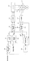
一方、同期機の脱調を防止し、且つ、高価な位置センサを使用することなく同期機を制御することが出来る制御方式として、センサレスベクトル制御がある。このセンサレスベクトル制御の制御ブロックを図1に示す。インバータ110の出力電流は、電流検出器112により検出され、この検出された三相電流は、3/2相変換部117、静止/回転座標変換部118により、回転座標系上の二相電流Id,Iqに変換された後、磁化電圧制御部122およびトルク電圧制御部121に入力される。磁化電圧制御部122は、現在の磁化電流Idと磁化電流指令値Id*との偏差が0となるような磁化電圧指令値Vd*をPI演算により求める。トルク電圧制御部121は、現在のトルク電流Iqとトルク電流指令値Iq*との偏差が0となるようなトルク電圧指令値Vq*をPI演算により求める。
On the other hand, there is sensorless vector control as a control method that can prevent the synchronous machine from stepping out and can control the synchronous machine without using an expensive position sensor. A control block of this sensorless vector control is shown in FIG. The output current of the
目標トルク電流決定部124は、外部から入力された角速度指令値ω*と現在の角速度ωとの偏差が0となるようにPI演算を行なってトルク電流指令値Iq*を決定する。現在の角速度ωは、電圧指令値Vd*,Vq*およびフィードバック電流Id,Iqに基づき、軸誤差推定器129および微分器132によって求められる。磁化電流指令値Id*は、モータモデルを用いて算出された理想的な磁化電流である。電圧指令値Vd*,Vq*は、回転/静止座標変換部135および2/3相変換部136を経て固定座標系上の3相電圧指令値に変換された後、インバータ110に送られる。
The target torque
この図1に示すセンサレスベクトル制御は、位置センサを用いずに、フィードバックされたモータ電流からロータの位置を推定する制御方式である。この制御方式は、モータモデルに基づいて負荷の状態に見合った最適な制御をしているため、モータの効率を最大限に発揮させることが出来る。 The sensorless vector control shown in FIG. 1 is a control method for estimating the position of the rotor from the fed back motor current without using a position sensor. Since this control method performs optimal control corresponding to the load state based on the motor model, the efficiency of the motor can be maximized.
しかしながら、センサレスベクトル制御では、フィードバックされたモータ電流から電圧指令値を高速周期で演算する必要がある。また、モータモデルが必要なため、モータMの巻線抵抗やリアクタンス等の多くのモータ定数を制御に用いる必要がある。正確なモータ定数を把握するためには手間がかかる上、それら巻線抵抗およびリアクタンスの温度依存も考慮する必要がある。 However, in the sensorless vector control, it is necessary to calculate the voltage command value from the fed back motor current at a high speed cycle. Further, since a motor model is required, it is necessary to use many motor constants such as winding resistance and reactance of the motor M for control. In order to grasp an accurate motor constant, it takes time and it is necessary to consider the temperature dependence of the winding resistance and reactance.
本発明は上述した従来の問題点に鑑みてなされたもので、従来のV/F制御だけではなし得なかった高効率化や最適トルク制御を実現しつつ、従来のセンサレスベクトル制御で必要とされたモータの巻線抵抗やリアクタンスなどのモータ定数を使用せずにモータを駆動することができる電動機の駆動装置を提供することを目的とする。 The present invention has been made in view of the above-described conventional problems, and is required for conventional sensorless vector control while realizing high efficiency and optimum torque control that cannot be achieved by conventional V / F control alone. Another object of the present invention is to provide an electric motor drive device that can drive a motor without using motor constants such as winding resistance and reactance of the motor.
上述した目的を達成するために、本発明の一態様は、インバータと、該インバータの出力電流を検出する電流検出器と、該電流検出器により検出された出力電流をトルク電流および磁化電流に変換し、該トルク電流および磁化電流を制御するベクトル制御部とを備えた電動機の駆動装置であって、前記ベクトル制御部は、前記電流検出器により検出された三相電流を二相電流に変換する3/2相変換部と、前記3/2相変換部によって変換された静止座標系上の前記二相電流を回転座標系上のトルク電流および磁化電流に変換する静止/回転座標変換部と、トルク電流指令値と前記トルク電流との偏差に基づいてトルク電圧指令値を決定するトルク電圧制御部と、磁化電流指令値と前記磁化電流との偏差に基づいて磁化電圧指令値を決定する磁化電圧制御部と、回転座標系上の前記トルク電圧指令値および前記磁化電圧指令値を、静止座標系上のトルク電圧指令値および磁化電圧指令値に変換する回転/静止座標変換部と、前記回転/静止座標変換部によって変換された前記トルク電圧指令値および前記磁化電圧指令値を三相の電圧指令値に変換する2/3相変換部と、前記トルク電圧制御部および前記磁化電圧制御部により求められた前記トルク電圧指令値および前記磁化電圧指令値から前記電動機のロータの角速度を算出する速度演算部と、前記角速度と角速度指令値との偏差に基づいて前記トルク電流指令値を決定する目標トルク電流決定部と、前記インバータの出力電圧と目標出力電圧との偏差に基づいて前記磁化電流指令値を決定する目標磁化電流決定部と、前記目標出力電圧を決定する目標出力電圧決定部とを備えることを特徴とする。
In order to achieve the above-described object, one embodiment of the present invention includes an inverter, a current detector that detects an output current of the inverter, and an output current detected by the current detector is converted into a torque current and a magnetizing current. And a vector controller that controls the torque current and the magnetizing current, wherein the vector controller converts the three-phase current detected by the current detector into a two-phase current. A 3/2 phase converter, and a static / rotary coordinate converter for converting the two-phase current on the stationary coordinate system converted by the 3/2 phase converter into a torque current and a magnetizing current on the rotating coordinate system; A torque voltage control unit that determines a torque voltage command value based on a deviation between the torque current command value and the torque current, and a magnetization voltage command value based on a deviation between the magnetization current command value and the magnetization current A voltage / voltage control unit, a rotation / stationary coordinate conversion unit that converts the torque voltage command value and the magnetization voltage command value on a rotating coordinate system into a torque voltage command value and a magnetization voltage command value on a stationary coordinate system,
本発明の好ましい態様は、前記目標出力電圧決定部は、前記目標出力電圧と前記角速度との関係を示すV/ωパターンを記憶しており、該V/ωパターンに従って、前記角速度から前記目標出力電圧を決定することを特徴とする。
本発明の好ましい態様は、前記V/ωパターンによって示される前記目標出力電圧と前記角速度との関係は、前記目標出力電圧と前記角速度との比が一定となる関係であることを特徴とする。
本発明の好ましい態様は、前記V/ωパターンによって示される前記目標出力電圧と前記角速度との関係は、前記目標出力電圧と前記角速度との比が二次低減カーブで表される関係であることを特徴とする。
本発明の好ましい態様は、前記目標出力電圧決定部は、前記目標出力電圧と前記角速度との関係を示す複数のV/ωパターンを記憶しており、該複数のV/ωパターンの中から選択された1つのV/ωパターンに従って、前記角速度から前記目標出力電圧を決定することを特徴とする。
In a preferred aspect of the present invention, the target output voltage determination unit stores a V / ω pattern indicating a relationship between the target output voltage and the angular velocity, and the target output is calculated from the angular velocity according to the V / ω pattern. The voltage is determined.
In a preferred aspect of the present invention, the relationship between the target output voltage and the angular velocity indicated by the V / ω pattern is a relationship in which a ratio between the target output voltage and the angular velocity is constant.
In a preferred aspect of the present invention, the relationship between the target output voltage and the angular velocity indicated by the V / ω pattern is a relationship in which a ratio between the target output voltage and the angular velocity is represented by a secondary reduction curve. It is characterized by.
In a preferred aspect of the present invention, the target output voltage determination unit stores a plurality of V / ω patterns indicating a relationship between the target output voltage and the angular velocity, and is selected from the plurality of V / ω patterns. The target output voltage is determined from the angular velocity according to one V / ω pattern.
本発明の好ましい態様は、前記V/ωパターンによって示される前記目標出力電圧と前記角速度との関係は、前記目標出力電圧が前記電動機の定格電圧に達した後は、前記目標出力電圧は前記定格電圧で一定に維持される関係であることを特徴とする。
本発明の好ましい態様は、前記V/ωパターンによって示される前記目標出力電圧と前記角速度との関係は、前記目標出力電圧が前記インバータの定格出力電圧に達した後は、前記目標出力電圧は前記定格出力電圧で一定に維持される関係であることを特徴とする。
本発明の好ましい態様は、前記目標磁化電流決定部は、前記角速度が所定の値以下の場合は、該目標磁化電流決定部に記憶されている下限値を前記磁化電流指令値として出力することを特徴とする。
本発明の好ましい態様は、前記磁化電圧制御部は、前記角速度が所定の値以下の場合は、該磁化電圧制御部に記憶されている下限値を前記磁化電圧指令値として出力することを特徴とする。
In a preferred aspect of the present invention, the relationship between the target output voltage indicated by the V / ω pattern and the angular velocity is such that after the target output voltage reaches the rated voltage of the motor, the target output voltage is It is characterized in that the relationship is kept constant with voltage.
In a preferred aspect of the present invention, the relationship between the target output voltage indicated by the V / ω pattern and the angular velocity is such that after the target output voltage reaches the rated output voltage of the inverter, the target output voltage is It is characterized in that the relationship is maintained constant at the rated output voltage.
In a preferred aspect of the present invention, when the angular velocity is equal to or less than a predetermined value, the target magnetization current determination unit outputs a lower limit value stored in the target magnetization current determination unit as the magnetization current command value. Features.
In a preferred aspect of the present invention, the magnetization voltage control unit outputs a lower limit value stored in the magnetization voltage control unit as the magnetization voltage command value when the angular velocity is equal to or less than a predetermined value. To do.
本発明によれば、目標出力電圧の決定には、電動機の定格電圧および定格周波数のみが必要となり、電動機の巻線抵抗やリアクタンスなどのモータ定数は不要である。さらには、目標出力電圧決定部に記憶されているV/ωパターンに従って目標出力電圧が決定されるので、複雑な演算が不要である。したがって、安定した電動機の駆動を実現することができる。 According to the present invention, determining the target output voltage requires only the rated voltage and rated frequency of the motor, and does not require motor constants such as winding resistance and reactance of the motor. Furthermore, since the target output voltage is determined according to the V / ω pattern stored in the target output voltage determination unit, complicated calculation is not necessary. Therefore, stable driving of the electric motor can be realized.
以下、本発明の実施形態について図面を参照して説明する。
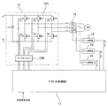
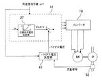
図2は、本発明の一実施形態に係る駆動装置を示すブロック図である。この駆動装置は、モータMを駆動するインバータ装置(電力変換装置)であり、図2に示すようにインバータ10およびベクトル制御部11を含む複数の要素から構成されている。すなわち、駆動装置は、モータMに供給される電圧を生成するインバータ10と、インバータ10への電圧指令値を決定するベクトル制御部11と、インバータ10からモータMに供給される電流を検出する電流検出器(電流計)12とを備えている。
Embodiments of the present invention will be described below with reference to the drawings.
FIG. 2 is a block diagram showing a driving apparatus according to an embodiment of the present invention. This drive device is an inverter device (power conversion device) for driving the motor M, and includes a plurality of elements including the
図3は、図2に示すインバータ10を詳細に示す模式図である。インバータ10は、電力変換部としてのインバータ回路10Aと、このインバータ回路10Aを駆動するゲートドライバ10Bとから基本的に構成されている。インバータ回路10Aでは、直流電力(例えば、商用電源を全波整流して得られる直流電源からの直流電力)が供給される正極ラインPと負極ラインNとの間に3組の上下アームが並列に接続されており、各相の上下アームにはスイッチング素子(IGBT)S1〜S6とダイオードD1〜D6とからなる逆並列回路が組み込まれている。記号C1はコンデンサである。これらスイッチング素子S1〜S6、ダイオードD1〜D6、およびコンデンサC1によりインバータ回路10Aが構成されている。ゲートドライバ10Bは、ベクトル制御部11から送られる電圧指令値に従った電圧が生成されるように、インバータ回路10Aのスイッチング素子S1〜S6を駆動する。
FIG. 3 is a schematic diagram showing in detail the
電流検出器12は、インバータ10からモータMに供給される三相電流Iu,Iv,Iwを計測する。その計測値は、ゲイン調整器15によって増幅された後、ベクトル制御部11に入力される。なお、ゲイン調整器15は省略することもできる。なお、三相電流Iu,Iv,Iwの計測は、任意の2相の電流を計測し、式Iu+Iv+Iw=0から残りの電流を求めてもよい。ベクトル制御部11は、三相電流Iu,Iv,Iwおよび外部から入力される角速度指令値に基づいて三相電圧指令値Vu*,Vv*、Vw*を生成する。さらに、ベクトル制御部11は、これら三相電圧指令値Vu*,Vv*、Vw*に対応したPWM信号を生成し、このPWM信号をゲートドライバ10Bに送る。ゲートドライバ10Bは、三相電圧指令値Vu*,Vv*、Vw*に対応するPWM信号に基づいてゲートドライブPWM信号を生成し、6個のスイッチング素子S1〜S6は、ゲートドライブPWM信号に基づいて動作(オン、オフ)される。このように、インバータ10はベクトル制御部11からの三相電圧指令値に基づいた電圧を生成し、これをモータMに印加する。
The
ベクトル制御部11の基本的動作は次の通りである。電流検出器12によって検出されたインバータ10の三相出力電流は、回転座標系上の二相電流(ベクトル)に変換される。ここで、回転座標系の一方の軸を1次鎖交磁束の方向に一致させると、他方の軸は1次鎖交磁束に直交する。したがって、1次鎖交磁束に直交する軸上の電流ベクトルを制御することによって、モータMのトルクを制御することができる。すなわち、変換された二相電流とそれぞれの目標値との偏差がなくなるようにPI制御が行なわれ、二相の電圧指令値が求められる。求められた回転座標系上の二相の電圧指令値は、静止座標系上の三相の電圧指令値に変換される。そして、各相の電圧指令値に対応したPWM信号が生成され、このPWM信号はインバータ10のゲートドライバ10Bに送られる。ベクトル制御部11は、CPU(中央演算処理装置)または専用の処理装置から構成することができる。
The basic operation of the
次に、図2を参照してベクトル制御部11について詳細に説明する。電流検出器12によって検出された三相電流Iu,Iv,Iwは3/2相変換部17に送られ、ここで静止座標系上の三相電流Iu,Iv,Iwは静止座標系上の二相電流に変換される。この静止座標系上の二相電流は静止/回転座標変換部18に送られ、ここで位相θに基づいて回転座標系上の二相電流、すなわち磁化電流Imおよびトルク電流Itに変換される。
Next, the
トルク電流Itおよび磁化電流Imは、トルク電圧制御部21および磁化電圧制御部22にそれぞれ送られる。トルク電圧制御部21には、目標トルク電流決定部24からトルク電流指令値It*が入力される。そして、トルク電圧制御部21は、トルク電流指令値It*と現在のトルク電流Itとの偏差が0となるようにPI演算を行ない、トルク電圧指令値Vt*を求める。目標トルク電流決定部24は速度制御部であり、ベクトル制御部11の外部から入力される角速度指令値ω*と、モータMの現在の角速度ωとの偏差が0となるようなトルク電流指令値It*をPI演算により求める。
The torque current It and the magnetizing current Im are sent to the
磁化電圧制御部22には、目標磁化電流決定部26から磁化電流指令値Im*が入力される。磁化電圧制御部22は、磁化電流指令値Im*と現在の磁化電流Imとの偏差が0となるようにPI演算を行ない、磁化電圧指令値Vm*を求める。目標磁化電流決定部26は、目標出力電圧決定部27(後で詳述する)から送られる目標出力電圧Vout-dと現在の出力電圧Vとの偏差が0となるような磁化電流指令値Im*をPI演算により求める。
A magnetization current command value Im * is input from the target magnetization
インバータ10の現在の出力電圧Vは、トルク電圧指令値Vt*および磁化電圧指令値Vm*から出力電圧算出部30によって求められる。また、トルク電圧指令値Vt*および磁化電圧指令値Vm*は速度演算部31にも送られ、ここでロータの現在の角速度ωが求められる。この角速度ωは、目標トルク電流決定部24、目標出力電圧決定部27、および積分器33に入力される。積分器33は、角速度ωを積分してロータの位相θを求める。この位相θは静止/回転座標変換部18および回転/静止座標変換部35に入力される。
The current output voltage V of the
磁化電圧指令値Vm*およびトルク電圧指令値Vt*は、回転/静止座標変換部35に入力され、ここで回転座標系上の磁化電圧指令値Vm*およびトルク電圧指令値Vt*は、位相θに基づき静止座標系上のトルク電圧指令値および磁化電圧指令値に変換される。さらに2/3相変換部36により、静止座標系上のトルク電圧指令値および磁化電圧指令値は、三相(u相、v相、w相)の電圧指令値Vu*,Vv*,Vw*に変換される。インバータ10は、上述したように、電圧指令値Vu*,Vv*,Vw*に従って電圧を生成する。
The magnetization voltage command value Vm * and the torque voltage command value Vt * are input to the rotation / stationary coordinate
ここで、ベクトル制御部11が永久磁石型同期モータを制御する場合について説明する。
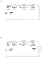
dq回転座標系において、ロータの永久磁石による磁束の方向をd軸とし、d軸に直交する軸をq軸とすると、同期モータの等価回路は図4(a)および図4(b)に示すようになる。図4(a)および図4(b)において、Rは巻線抵抗を表し、Ldはd軸方向のインダクタンスを表し、Lqはq軸方向のインダクタンスを表し、ωは角速度を表し、Eは誘起電圧を表している。
Here, the case where the
In the dq rotating coordinate system, assuming that the direction of the magnetic flux by the permanent magnet of the rotor is the d-axis and the axis orthogonal to the d-axis is the q-axis, the equivalent circuit of the synchronous motor is shown in FIGS. 4 (a) and 4 (b). It becomes like this. 4 (a) and 4 (b), R represents winding resistance, Ld represents inductance in the d-axis direction, Lq represents inductance in the q-axis direction, ω represents angular velocity, and E represents induction. Represents voltage.
図4(a)はd軸の方向に電流Idが流れたときの等価回路を示し、図4(b)はq軸の方向に電流Iqが流れたときの等価回路を示す。図4(a)および図4(b)により、電圧方程式は次のように表される。
Vd=Id・R+pLdId−ωLqIq (1)
Vq=Iq・R+pLqIq+ωLdId+E (2)
ここで、pは時間微分(d/dt)を表す。図4(a)および図4(b)に示す記号jは虚数単位を表している。干渉成分jωLqIq,jωLdIdをdq軸(モータ軸)上に表すと、ベクトルの方向が変換されて記号jがとれるので、記号jは式(1)および式(2)は表されていない。なお、式(1)および式(2)において、誘起電圧Eは、角速度ωと永久磁石による鎖交磁束Ψとの積である。
FIG. 4A shows an equivalent circuit when the current Id flows in the direction of the d-axis, and FIG. 4B shows an equivalent circuit when the current Iq flows in the direction of the q-axis. 4A and 4B, the voltage equation is expressed as follows.
Vd = Id · R + pLdId−ωLqIq (1)
Vq = Iq · R + pLqIq + ωLdId + E (2)
Here, p represents time differentiation (d / dt). A symbol j shown in FIGS. 4A and 4B represents an imaginary unit. When the interference components jωLqIq and jωLdId are represented on the dq axis (motor shaft), the direction of the vector is converted to obtain the symbol j, and therefore the symbol j does not represent the equations (1) and (2). In the equations (1) and (2), the induced voltage E is the product of the angular velocity ω and the interlinkage magnetic flux Ψ by the permanent magnet.
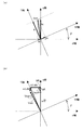
ここで、インダクタンス成分(L)があるため、インバータ10の出力電流Ioutに対して、出力電圧Voutには位相遅れが生じる。図5はインバータ10の出力電流Ioutおよび出力電圧Voutをベクトルで表した図である。図5において、モータがある理想的な制御状態にあるときの出力電圧Vout-iの位相に一致する軸をT軸とし、そのT軸に垂直な軸をM軸とする。MT軸とdq軸との間には、位相差βが存在する。本実施形態では、T軸上の電圧Vt,電流It、およびM軸上の電圧Vm,電流Imを用いてモータのベクトル制御を行なう。
Here, since there is an inductance component (L), the output voltage Vout has a phase lag with respect to the output current Iout of the
MT軸はインバータ10を制御する軸になるため、本明細書ではインバータ軸と呼称する。位相差βを把握するには、Ψ,Ld,Lq等が必要になるため、詳細なモータ定数が必要となるが、本実施形態では、このような詳細なモータ定数がなくともIt,Imが制御できる手法を採用している。
Since the MT axis serves as an axis for controlling the
本実施形態では、T軸を基準軸として、T軸に電圧Vtを、M軸に電圧Vmをそれぞれ印加し、出力電流Ioutがq軸に一致するように制御する。このような制御を行なうことにより位相差βが不明であっても、出力電流Ioutをq軸に一致させることが出来るので、モータMの定数を必要としない。 In this embodiment, with the T axis as the reference axis, the voltage Vt is applied to the T axis and the voltage Vm is applied to the M axis, and the output current Iout is controlled to coincide with the q axis. By performing such control, even if the phase difference β is unknown, the output current Iout can be made to coincide with the q axis, so that the constant of the motor M is not required.
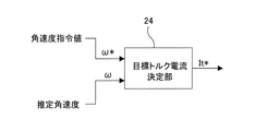
トルク電流Itの目標値を決定する制御ブロックを図6に示す。トルク電流の目標値、すなわちトルク電流指令値It*は、目標トルク電流決定部24によって生成される。この目標トルク電流決定部24には、角速度指令値ω*および現在の角速度ωが入力され、目標トルク電流決定部24はこれら2つの値ω*,ωの偏差を0とするためのトルク電流指令値It*を決定する。角速度指令値ω*は、モータMに要求される所望の角速度であり、ベクトル制御部11の外部から目標トルク電流決定部24に入力される。一方、現在の角速度ωは、速度演算部31によって与えられる。この速度演算部31は、ベクトル制御の結果得られるMT軸上の電圧指令値Vm*,Vt*の信号を処理することで推定角速度を求め、この求められた推定角速度が現在の角速度ωとして使用される。なお、速度演算部31は、トルク電圧指令値Vt*および磁化電圧指令値Vm*に基づいて角速度ωを算出できるものであれば、その形態は特に限定されない。例えば、速度演算部31は、PLL(Phase Locked Loop)回路や、その等価回帰演算を行なうものであってもよいし、電圧指令値と角速度との関係を予め関係式に表したものであってもよい。
A control block for determining the target value of the torque current It is shown in FIG. The target value of the torque current, that is, the torque current command value It * is generated by the target torque
目標トルク電流決定部24は、角速度指令値ω*が現在の角速度ωよりも大きければ(すなわち、ω*>ωであれば)、トルクを増やして増速させるためにより大きなトルク電流指令値It*を出力する。一方、角速度指令値ω*が現在の角速度ωよりも小さければ(すなわち、ω*<ωであれば)、トルクを減らして減速させるためにより小さなトルク電流指令値It*を出力する。
If the angular velocity command value ω * is greater than the current angular velocity ω (that is, if ω *> ω), the target torque
次に、磁化電流Imの目標値である磁化電流指令値Im*を決定するプロセスについて説明する。説明の簡略化のために、同期モータがSPMモータ(表面磁石型モータ、Surface Permanent Magnet motor)である場合を考える。SPMモータの場合は、インバータ10からの出力電流Ioutがd軸に垂直に流れるときが最も運転効率がよくなる。つまり、d軸上の電流Idが0となるようにインバータ10の出力電流を制御することが望ましい。図7(a)は、最も運転効率がよい状態におけるdq軸上の電流ベクトルとMT軸上の電流ベクトルとの関係を示している。
Next, a process for determining the magnetizing current command value Im * that is the target value of the magnetizing current Im will be described. In order to simplify the description, consider the case where the synchronous motor is an SPM motor (Surface Permanent Magnet motor). In the case of the SPM motor, the operation efficiency is best when the output current Iout from the
一方、インバータ10の出力電圧Voutは、式(1)および式(2)より次のように求められる。
Vout(→)=Vd(→)+Vq(→) (3)
Vout=Id・R+pLdId−ωLqIq
+Iq・R+pLqIq+ωLdId+ωΨ (4)
ただし、記号(→)はベクトルを表している。
On the other hand, the output voltage Vout of the
Vout (→) = Vd (→) + Vq (→) (3)
Vout = Id · R + pLdId−ωLqIq
+ Iq · R + pLqIq + ωLdId + ωΨ (4)
The symbol (→) represents a vector.
モータMが安定して運転している場合、フィードバック電流は綺麗な正弦波となる。このとき、座標変換された電流It,Imはほとんど変化しないため、定常状態にあるといえる。よって、上記式(4)の微分項は無視することができるので、上記式(4)は、
Vout=Id・R−ωLqIq+Iq・R+ωLdId+ωΨ
=Id・R+Iq・R+ω(LdId−LqIq+Ψ) (5)
と表される。
さらに、ベクトルIoutは、ベクトルIdとベクトルIqとの合成であるので、上記式(5)は、
Vout=Iout・R+ω(LdId−LqIq+Ψ) (6)
と表される。
When the motor M is operating stably, the feedback current is a clean sine wave. At this time, the currents It and Im that have undergone coordinate conversion hardly change, and thus can be said to be in a steady state. Therefore, since the differential term of the above equation (4) can be ignored, the above equation (4) is
Vout = Id · R−ωLqIq + Iq · R + ωLdId + ωΨ
= Id · R + Iq · R + ω (LdId−LqIq + Ψ) (5)
It is expressed.
Furthermore, since the vector Iout is a combination of the vector Id and the vector Iq, the above equation (5) is
Vout = Iout · R + ω (LdId−LqIq + Ψ) (6)
It is expressed.
図7(a)に示す状態においては、Id=0であるので、Iq=Ioutとなる。したがって、式(6)は次のように表される。
Vout=Iq・R−ωLqIq+ωΨ (7)
図7(b)は図7(a)に示すIoutに対応するVoutをベクトルで表した図である。図7(a)はIdが0となる理想状態を示しているため、このときの出力電圧を理想出力電圧Vout-iとする。そして、T軸は、この理想出力電圧Vout-iのベクトルの方向に一致する。
In the state shown in FIG. 7A, since Id = 0, Iq = Iout. Therefore, Formula (6) is expressed as follows.
Vout = Iq · R−ωLqIq + ωΨ (7)
FIG. 7B is a diagram showing Vout corresponding to Iout shown in FIG. Since FIG. 7A shows an ideal state where Id is 0, the output voltage at this time is an ideal output voltage Vout-i. The T axis coincides with the vector direction of the ideal output voltage Vout-i.
図8(a)は、出力電流Ioutが電流Iqに対して位相進みである場合、つまり、Id<0となる場合のIout、Iq、Id、It、Imの関係を示している。トルク電流Itが、トルク電流指令値It*に基づいて図7(a)の場合と同じ大きさで制御されている条件下では、ベクトルIoutの先端は、ベクトルItの先端を通る、T軸に垂直な直線上にある。したがって、ベクトルIqは図7(a)に示す理想状態の時よりも小さくなる。このときの電圧Voutのベクトルは図8(b)に示すようになる。Id<0であるため、IdRは左向きのベクトルとなり、ωLdIdは下向きのベクトルとなる。これらのベクトルの存在とIqが小さくなることから、出力電圧Voutは、点線で示す理想出力電圧Vout-i(図7(b)参照)よりも小さくなる。このとき、M軸上の電流Imは、図7(a)に示す理想状態における電流Imよりも小さくなる。 FIG. 8A shows the relationship between Iout, Iq, Id, It, and Im when the output current Iout is in phase advance with respect to the current Iq, that is, when Id <0. Under the condition that the torque current It is controlled to the same magnitude as in the case of FIG. 7A based on the torque current command value It *, the tip of the vector Iout passes through the tip of the vector It. It is on a vertical straight line. Therefore, the vector Iq is smaller than that in the ideal state shown in FIG. The vector of the voltage Vout at this time is as shown in FIG. Since Id <0, IdR is a leftward vector, and ωLdId is a downward vector. Since these vectors are present and Iq is reduced, the output voltage Vout is smaller than the ideal output voltage Vout-i (see FIG. 7B) indicated by a dotted line. At this time, the current Im on the M-axis is smaller than the current Im in the ideal state shown in FIG.
一方、図9(a)は、出力電流Ioutが電流Iqに対して位相遅れである場合、つまり、Id>0となる場合のIout、Iq、Id、It、Imの関係を示している。トルク電流Itが、トルク電流指令値It*に基づいて図7(a)の場合と同じ大きさで制御されている条件下では、Iqは図7(a)に示す理想状態の時よりも大きくなる。このときの電圧Voutのベクトルは図9(b)に示すようになる。Id>0であるため、IdRが右向きのベクトルとなり、ωLdIdは上向きのベクトルとなる。これらのベクトルの存在とIqが大きくなることから、出力電圧Voutは、点線で示す理想出力電圧Vout-i(図7(b)参照)よりも大きくなる。このとき、M軸上の電流Imは、図7(a)に示す理想状態における電流Imよりも大きくなる。 On the other hand, FIG. 9A shows the relationship of Iout, Iq, Id, It, Im when the output current Iout is delayed in phase with respect to the current Iq, that is, when Id> 0. Under the condition that the torque current It is controlled to the same magnitude as in FIG. 7A based on the torque current command value It *, Iq is larger than that in the ideal state shown in FIG. Become. The vector of the voltage Vout at this time is as shown in FIG. Since Id> 0, IdR is a rightward vector, and ωLdId is an upward vector. Because of the presence of these vectors and Iq, the output voltage Vout becomes larger than the ideal output voltage Vout-i (see FIG. 7B) indicated by the dotted line. At this time, the current Im on the M-axis becomes larger than the current Im in the ideal state shown in FIG.
図7(a)〜図9(b)から、磁化電流Imについて以下のことがわかる。ある理想的な出力電圧Vout-iに対して、実際の出力電圧Voutが小さい場合は、磁化電流Imを大きくして、出力電流Ioutの位相を遅らせることによって出力電圧Voutを理想出力電圧Vout-iに近づけることができる。一方、理想出力電圧Vout-iに対して、実際の出力電圧Voutが大きい場合は、磁化電流Imを小さくして、出力電流Ioutの位相を進めることによって出力電圧Voutを理想出力電圧Vout-iに近づけることができる。つまり、ある運転状態に対して目標となる出力電圧を定め、目標出力電圧と実際の出力電圧との偏差を求めることによって、磁化電流指令値Im*を決定することができる。 From FIG. 7 (a) to FIG. 9 (b), the following can be understood for the magnetizing current Im. When the actual output voltage Vout is smaller than a certain ideal output voltage Vout-i, the magnetizing current Im is increased and the phase of the output current Iout is delayed to change the output voltage Vout to the ideal output voltage Vout-i. Can be approached. On the other hand, when the actual output voltage Vout is larger than the ideal output voltage Vout-i, the magnetizing current Im is decreased and the phase of the output current Iout is advanced to change the output voltage Vout to the ideal output voltage Vout-i. You can get closer. That is, the magnetizing current command value Im * can be determined by determining a target output voltage for a certain operating state and obtaining a deviation between the target output voltage and the actual output voltage.
上述したSPMモータでは、モータステータの巻線が生成する磁束は、永久磁石による磁気抵抗を均一に受ける。したがって、d軸インダクタンスLdとq軸インダクタンスLqとは互いに等しくなる。一方、IPMモータ(埋込磁石型モータ、Interior Permanent Magnet motor)の場合は、d軸方向の磁束は永久磁石による磁気抵抗を受けるが、q軸方向の磁束は鉄心のみを通過する。したがって、d軸インダクタンスLdとq軸インダクタンスLqとの間には差が存在する。このため、出力電流Ioutがq軸からある位相進みを持っている時が最も駆動効率が良くなる。しかしながら、この位相進みの角度は詳細なモータ定数がないと算出することができない。 In the SPM motor described above, the magnetic flux generated by the motor stator winding is uniformly subjected to the magnetic resistance by the permanent magnet. Therefore, the d-axis inductance Ld and the q-axis inductance Lq are equal to each other. On the other hand, in the case of an IPM motor (Interior Permanent Magnet motor), the magnetic flux in the d-axis direction is subjected to magnetic resistance by a permanent magnet, but the magnetic flux in the q-axis direction passes only through the iron core. Therefore, there is a difference between the d-axis inductance Ld and the q-axis inductance Lq. For this reason, the drive efficiency is best when the output current Iout has a phase advance from the q axis. However, this phase advance angle cannot be calculated without detailed motor constants.
しかしながら、IPMモータの場合でも、図8(a)〜図9(b)に示した関係は成立する。すなわち、理想出力電圧Vout-iに対して、Imを大きくするとVoutは大きくなり、Imを小さくするとVoutが小さくなる。したがって、IPMモータにおいても、ある運転状態に対して目標となる出力電圧を定め、目標出力電圧と実際の出力電圧との偏差を求めることによって、磁化電流指令値Im*を決定することができる。 However, even in the case of an IPM motor, the relationship shown in FIGS. 8A to 9B is established. That is, with respect to the ideal output voltage Vout-i, when Im is increased, Vout increases, and when Im is decreased, Vout decreases. Therefore, also in the IPM motor, the magnetizing current command value Im * can be determined by determining a target output voltage for a certain operating state and obtaining a deviation between the target output voltage and the actual output voltage.
誘導モータの場合には、同期モータと異なり、磁束発生のために多くの磁化電流Idを流す必要があり、これによって生じた磁束に直交するd軸に誘起電力Eが生じる。しかし、誘導モータの場合でも、図8(a)〜図9(b)に示した関係が同様に成立する。すなわち、理想出力電圧Vout-iに対して、Imを大きくするとVoutは大きくなり、Imを小さくするとVoutが小さくなる。したがって、ある運転状態に対して目標となる出力電圧を定め、目標出力電圧と実際の出力電圧との偏差を求めることによって、磁化電流指令値Im*を決定することができる。 In the case of an induction motor, unlike a synchronous motor, it is necessary to flow a large amount of magnetizing current Id in order to generate magnetic flux, and induced electric power E is generated on the d axis perpendicular to the magnetic flux generated thereby. However, even in the case of an induction motor, the relationships shown in FIGS. 8A to 9B are similarly established. That is, with respect to the ideal output voltage Vout-i, when Im is increased, Vout increases, and when Im is decreased, Vout decreases. Therefore, the magnetizing current command value Im * can be determined by determining a target output voltage for a certain operating state and obtaining a deviation between the target output voltage and the actual output voltage.
本実施形態では、理想出力電圧Vout-iに対応する目標出力電圧Vout-dが予め定められており、この目標出力電圧Vout-dと現在の出力電圧との偏差に基づいて、磁化電流の目標値Im*が決定される。ベクトル制御部11には、後に詳述するように、目標出力電圧Vout-dと角速度ωとの関係を示すV/ωパターンが記憶されており、ベクトル制御部11は、現在の角速度ωに対応する目標出力電圧Vout-dをV/ωパターンに従って決定し、さらに目標出力電圧Vout-dと現在の出力電圧Vとの偏差に基づいて、磁化電流の目標値を決定する。
In this embodiment, a target output voltage Vout-d corresponding to the ideal output voltage Vout-i is determined in advance, and based on the deviation between the target output voltage Vout-d and the current output voltage, the target of the magnetizing current is determined. The value Im * is determined. As will be described in detail later, the
磁化電流Imの目標値である磁化電流指令値Im*を決定する制御のブロックを図10に示す。図10に示すように、磁化電流指令値Im*は、目標出力電圧Vout-dと、現在の出力電圧Vとを目標磁化電流決定部26に入力することで求められる。現在の出力電圧Vは、ベクトル制御の結果得られるMT軸上の電圧指令値Vm*,Vt*の信号を合成して得ることができる(V=√(Vm*2+Vt*2))。目標磁化電流決定部26は、目標出力電圧Vout-dと現在の出力電圧Vとの偏差が0となるような磁化電流指令値Im*を求める。すなわち、目標磁化電流決定部26は、Vout-d>Vであれば出力電流Ioutの位相を遅らせるようにより大きなIm*を出力し、Vout-d<Vであれば出力電流Ioutの位相を進ませるようにより小さなIm*を出力する。
FIG. 10 shows a control block for determining the magnetizing current command value Im *, which is the target value of the magnetizing current Im. As shown in FIG. 10, the magnetizing current command value Im * is obtained by inputting the target output voltage Vout-d and the current output voltage V to the target magnetizing current determining
トルク電流指令値It*および磁化電流指令値Im*は、図2に示すように、トルク電圧制御部21および磁化電圧制御部22にそれぞれ入力される。そして、上述したように、トルク電圧制御部21は、現在のトルク電流Itとトルク電流指令値It*との偏差に基づいてトルク電圧指令値Vt*を算出する。磁化電圧制御部22は、現在の磁化電流Imと磁化電流指令値Im*との偏差に基づいて磁化電圧指令値Vm*を算出する。このようにして、インバータ軸であるMT軸上のベクトルを用いたベクトル制御が可能となる。
The torque current command value It * and the magnetizing current command value Im * are input to the torque
目標出力電圧Vout-dは、目標出力電圧決定部27から出力され、目標磁化電流決定部26に入力される。目標出力電圧決定部27は、現在の角速度ωに基づいて目標出力電圧Vout-dを決定する。より具体的には、目標出力電圧決定部27には、目標出力電圧Vout-dと角速度ωとの関係を示すV/ωパターンが記憶されている。このV/ωパターンは、現在のロータの角速度ωに対応する目標出力電圧Vout-dを決定するための、角速度ωと目標出力電圧Vout-dとの対応関係を定義する。V/ωパターンは、目標出力電圧Vout-dと角速度ωとの関係を示す関数またはテーブルデータとして目標出力電圧決定部27に記憶されている。目標出力電圧決定部27は、V/ωパターンに基づいて、現在の角速度ωに対応する目標出力電圧Vout-dを決定する。なお、公知の式ω=2πFを用いて、角速度ωから周波数Fを求めることができるので、目標出力電圧Vout-dと周波数Fとの関係を示すV/Fパターンを目標出力電圧決定部27に記憶させてもよい。
The target output voltage Vout-d is output from the target output
目標出力電圧Vout-dと角速度ωとの関係は、Vout-dとωとの比が一定となる関係でもよいし、負荷トルクがモータの回転速度の二乗に比例するポンプやファンなどを駆動する場合は、Vout-dとωとの比が、二乗低減トルク特性に沿った二乗低減カーブで表されてもよい。V/ωパターンは、従来のV/F制御と同様の手法に従って、モータMの定格電圧と定格周波数とから設定することができる。 The relationship between the target output voltage Vout-d and the angular velocity ω may be a relationship in which the ratio between Vout-d and ω is constant, or a pump or fan whose load torque is proportional to the square of the rotational speed of the motor is driven. In this case, the ratio between Vout-d and ω may be represented by a square reduction curve along the square reduction torque characteristic. The V / ω pattern can be set from the rated voltage and the rated frequency of the motor M according to the same method as the conventional V / F control.
モータ効率を最大とするためには、目標出力電圧Vout-dは、理想的な出力電圧Vout-iに一致することが望ましい。しかしながら、目標出力電圧Vout-dが理想出力電圧Vout-iから大きく外れなければ、モータMの制御は可能である。本実施形態に係る駆動装置は、従来のV/F制御とは異なり、インバータ10の出力電流をベクトル制御部11にフィードバックすることで、ロータの脱調を回避することができる。また、出力電圧Vを目標磁化電流決定部26にフィードバックするため、単なるV/F制御よりも精度および効率のよい制御が可能になる。
In order to maximize the motor efficiency, it is desirable that the target output voltage Vout-d matches the ideal output voltage Vout-i. However, if the target output voltage Vout-d does not deviate significantly from the ideal output voltage Vout-i, the motor M can be controlled. Unlike the conventional V / F control, the drive device according to the present embodiment can avoid the step-out of the rotor by feeding back the output current of the
さらに、Vout-d/ωが一定となる一次関数を設定するには、図11(a)に示すように、モータMの定格電圧と定格周波数(または定格回転速度)とが分かれば十分であり、詳細なモータ定数は不要である。また、目標出力電圧Vout-dと角速度ωとの比を二乗低減カーブで表す場合でも、図11(b)に示すように、モータMの定格電圧と定格周波数が分かれば、低減分を任意に設定することができる。 Further, in order to set a linear function in which Vout-d / ω is constant, it is sufficient to know the rated voltage and rated frequency (or rated rotational speed) of the motor M as shown in FIG. Detailed motor constants are not necessary. Even when the ratio between the target output voltage Vout-d and the angular velocity ω is represented by a square reduction curve, if the rated voltage and rated frequency of the motor M are known as shown in FIG. Can be set.
なお、本実施形態における駆動装置において、弱め界磁制御を行なうこともできる。すなわち、モータMの周波数(回転速度)が該モータMの定格周波数を超えたときは、インバータ10の出力電力がモータMの定格電圧に維持されるように磁化電流Imが下げられる。これにより、インバータ10の出力電圧を抑えつつ、モータMの回転速度を上昇させることができる。図11(a)および図11(b)に示すV/ωパターンでは、目標出力電圧Vout-dがモータMの定格電圧に達した後は、目標出力電圧Vout-dはモータMの定格電圧で一定に維持される。すなわち、モータMの定格周波数に対応する角速度以上の領域では、目標出力電圧Vout-dはモータMの定格電圧に維持される。なお、インバータ10の出力上限電圧(DCリンク電圧から算出される)がモータMの定格電圧よりも小さい場合は、モータMの定格周波数に対応する角速度以上の領域では、目標出力電圧Vout-dはインバータ10の出力上限電圧に維持される。
It should be noted that field weakening control can also be performed in the drive device in the present embodiment. That is, when the frequency (rotational speed) of the motor M exceeds the rated frequency of the motor M, the magnetizing current Im is lowered so that the output power of the
ここで、目標出力電圧決定部27は、目標出力電圧Vout-dと角速度ωとの関係を示す複数のV/ωパターンを記憶してもよい。この場合は、図示しない入力部からの設定操作により、複数のV/ωパターンから1つのV/ωパターンが選択され、目標出力電圧決定部27は、選択されたV/ωパターンに従って、角速度ωから目標出力電圧Vout-dを決定する。例えば、目標出力電圧決定部27は、複数のV/ωパターンとして、Vout-d/ωが一定となるV/ωパターンと、Vout-d/ωが二乗低減カーブで表されるV/ωパターンとを記憶し、モータMに連結される負荷の種類によって適切なV/ωパターンを選択可能とすることができる。
Here, the target output
本実施形態では、低周波数領域でのトルクブーストを行なうことが可能である。一般に、モータの周波数(回転速度)が低い領域では、インバータ10の出力電流が小さくなるため、モータの制御が難しくなる。そこで、図12に示すように、モータMの角速度が所定の値以下の領域では、磁化電流指令値Im*の下限値を設けて、低周波数領域での磁化電流指令値Im*をブーストすることが好ましい。図12に示す例では、モータMのロータの角速度がω1以下であるとき、目標磁化電流決定部26は、予め記憶されている下限値を磁化電流指令値Im*として出力する。一方、角速度がω1よりも大きいときは、目標磁化電流決定部26は、PI制御の結果得られた磁化電流指令値Im*を出力する。このように、低周波数の領域において磁化電流指令値Im*を補償することにより、モータの低速領域でのトルクブーストを実現することができる。なお、図12において、磁化電流指令値Im*の下限値を示す線グラフが傾いている理由は、指令値Im*が大きいと過励磁になり効率が悪くなるためである。このような過励磁状態を避けて、適切な指令値で速やかな制御を行なうために、磁化電流指令値Im*の下限値を角速度の増加に従って減少させて指令値Im*を小さくしている。
In the present embodiment, it is possible to perform torque boost in the low frequency region. In general, in a region where the frequency (rotational speed) of the motor is low, the output current of the
なお、磁化電流指令値Im*に代えて、磁化電圧指令値Vm*に下限値を設けてもよい。この場合も、図12の例と同様に、磁化電圧制御部22は、角速度が所定の値以下であるとき、予め記憶されている下限値を磁化電圧指令値Vm*として出力し、一方、角速度が所定の値よりも大きいときは、PI制御の結果得られた磁化電圧指令値Vm*を出力する。この場合も、図12に示す例と同じように、磁化電圧指令値Vm*の下限値を角速度の増加に従って減少させて、適切な指令値で早く制御できるようにしている。
Instead of the magnetizing current command value Im *, a lower limit value may be provided for the magnetizing voltage command value Vm *. Also in this case, similarly to the example of FIG. 12, when the angular velocity is equal to or lower than the predetermined value, the magnetization
上述した低周波数領域でのトルクブーストは、磁化電流指令値Im*と磁化電圧指令値Vm*とのいずれかを選択して行なうようにしてもよい。より具体的には、磁化電流指令値Im*と磁化電圧指令値Vm*との両方に上記下限値を設け、磁化電流指令値Im*と磁化電圧指令値Vm*のいずれかの下限値を選択的に、目標磁化電流決定部26または磁化電圧制御部22から出力するようにしてもよい。磁化電圧指令値Vm*の下限値を選択した場合は、過電流を防止するために、磁化電流指令値Im*に上限値を設けて、過大な磁化電圧指令値Vm*に起因する過励磁での過電流保護を行うことが好ましい。
The torque boost in the low frequency region described above may be performed by selecting either the magnetizing current command value Im * or the magnetizing voltage command value Vm *. More specifically, the lower limit value is provided for both the magnetizing current command value Im * and the magnetizing voltage command value Vm *, and either of the magnetizing current command value Im * and the magnetizing voltage command value Vm * is selected. Alternatively, the output may be output from the target magnetization
本実施形態では、目標出力電圧決定部27において、角速度ωから目標出力電圧Vout-dが決定されるが、目標出力電圧決定部27から出力される目標出力電圧Vout-dが必ずしも理想出力電圧に一致するとは限らない。本発明では、目標出力電圧Vout-dと理想出力電圧との差によるモータ効率の低下を以下のように補償することもできる。
In the present embodiment, the target output
図13は、モータMに接続された負荷41にトルクメータ42が備わっている場合の、モータ効率低下の補償の例を示す図である。ベクトル制御部11は、その詳細を省略して図示されており、目標出力電圧決定部27とその出力のみが記載されている。バイアス電圧決定部43には、角速度指令値ω*およびトルクメータ42から出力されるトルク信号が入力され、バイアス電圧決定部43からはバイアス電圧が出力される。バイアス電圧は、目標出力電圧決定部27の出力である目標出力電圧Vout-dに加算され、その結果得られた値は目標磁化電流決定部26(図2参照)に入力される。ここで、バイアス電圧は正の値だけでなく、負の値も取ることができる。
FIG. 13 is a diagram illustrating an example of compensation for a decrease in motor efficiency when a
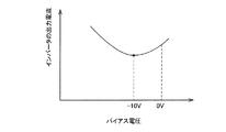
バイアス電圧決定部43は、角速度指令値ω*に変化がない場合に、トルクメータ42で検出されるトルクが最大となるように、バイアス電圧を増減させる。図14は、トルク信号とバイアス電圧との関係を示すグラフである。図14に示す例では、トルク信号は、バイアス電圧が−10Vのときに最大となる。バイアス電圧決定部43は、バイアス電圧を増減させる前後のトルク信号を比較し、バイアス電圧の増減を決定する。角速度指令値ω*が変化したときは、バイアス電圧を0に戻す。このように、バイアス電圧決定部43は、角速度指令値ω*が変化するまで、トルクが最大となるようにバイアス電圧を増減させる。
The bias
一般に、角速度指令値ω*の演算周期は、ベクトル制御の周期に比して長い。例えば、角速度指令値ω*は100ms間隔で演算されているのに対して、ベクトル制御の周期(目標出力電圧Vout-dの決定周期)が1msであれば、角速度指令値ω*が一定である間に、最低でも100回はバイアス電圧を増減させる機会が得られる。なお、バイアス電圧の増減はベクトル制御の周期と同じくしてもよいし、ベクトル制御の周期よりも長い周期で行なってもよい。例えば、上述の例において、バイアス電圧の増減を5ms毎に行なうようにしてもよい。 In general, the calculation cycle of the angular velocity command value ω * is longer than the cycle of vector control. For example, the angular velocity command value ω * is calculated at an interval of 100 ms, whereas the angular velocity command value ω * is constant if the vector control cycle (target output voltage Vout-d determination cycle) is 1 ms. In the meantime, there is an opportunity to increase or decrease the bias voltage at least 100 times. The increase / decrease of the bias voltage may be the same as the cycle of vector control or may be performed at a cycle longer than the cycle of vector control. For example, in the above example, the bias voltage may be increased or decreased every 5 ms.
図15は、モータMに接続される負荷がポンプPであって、ポンプPに連結される配管に流量計52が備わっている場合の、モータ効率低下の補償の例を示す図である。図16は、流量とバイアス電圧との関係を示すグラフである。図15に示す例が図13に示す例と異なる点は、バイアス電圧決定部43に入力される信号がトルク信号ではなく、流量計52から出力される流量信号である点と、バイアス電圧の増減が、流量が最大となるように行なわれる点である。その他の構成および動作は、図13に示す例と同様である。
FIG. 15 is a diagram illustrating an example of compensation for a decrease in motor efficiency when the load connected to the motor M is the pump P and the pipe connected to the pump P includes the
このように、モータMに接続された負荷の状態を検出するセンサ(トルクメータ42,流量計52)を用いて、その負荷状態が最大となるように、目標出力電圧Vout-dに加算するバイアス電圧を増減させることで、モータ効率をより高める制御を行なうことができる。
Thus, using the sensors (
また、モータ効率自体の補償ではなく、インバータの効率を高めるような制御を行ない、結果としてシステム全体の効率の補償を行なうこともできる。図13および図15に示した例は、モータの最高効率点を目指す制御であるが、モータの最高効率点での運転が、インバータ等を含めたシステム全体でも最も効率がよい運転とは限らない。そこで、モータの最大トルク点とは異なるが、インバータ出力電流が最小となるように目標出力電圧Vout-dに加算するバイアス電圧を増減して、インバータの効率を最大にする。 Further, it is possible not to compensate for the motor efficiency itself, but also to perform control to increase the efficiency of the inverter, and as a result, it is possible to compensate for the efficiency of the entire system. The example shown in FIGS. 13 and 15 is control aiming at the highest efficiency point of the motor, but the operation at the highest efficiency point of the motor is not always the most efficient operation in the entire system including the inverter and the like. . Therefore, although different from the maximum torque point of the motor, the bias voltage added to the target output voltage Vout-d is increased / decreased so that the inverter output current is minimized to maximize the inverter efficiency.
図17は、このような例を示す図である。図18は、インバータの出力電流とバイアス電圧との関係を示すグラフである。図17に示す例が、図13および図15に示す例と異なる点は、バイアス電圧決定部43に入力される信号が、モータMに接続された負荷の状態を表す信号ではなく、インバータ10の出力電流を示す信号である点と、バイアス電圧の増減がインバータ10の出力電流が最小となるように行なわれる点である。インバータ10の出力電流は、インバータ10の出力電流を検出するセンサ12からの信号をバイアス電圧決定部43に入力してもよい。
FIG. 17 is a diagram showing such an example. FIG. 18 is a graph showing the relationship between the output current of the inverter and the bias voltage. The example shown in FIG. 17 is different from the examples shown in FIGS. 13 and 15 in that the signal input to the bias
また、インバータの出力電流ではなく、出力電力が最小になるようにバイアス電圧を制御しても良い。インバータ10の出力電力は、インバータ10の出力電流および出力電圧から算出されるので、図17中に二点破線で示すようにインバータ10の出力電圧を検出するセンサ40を設けて、これら出力電流および出力電圧を検出するセンサ12,40からの信号をバイアス電圧決定部43に入力しても良い。また、インバータ10の出力電圧としては、センサ40からの信号を用いるのでなく、ベクトル制御部11で用いられる電圧指令値や出力電圧算出部30の出力を用いても良い。
Further, the bias voltage may be controlled so that the output power is minimized rather than the output current of the inverter. Since the output power of the
図19は、本発明の実施形態に係る駆動装置の変形例を示す図である。この変形例では、出力電圧は電圧指令値Vm*,Vt*から求められるのではなく、インバータ10の三相出力電圧が電圧検出器40によって直接検出される。検出された三相出力電圧は出力電圧算出部30に送られ、ここでインバータ10の出力電圧Vが求められる。得られた出力電圧Vは、上述の例と同様に、目標磁化電流決定部26に入力される。
FIG. 19 is a view showing a modification of the drive device according to the embodiment of the present invention. In this modification, the output voltage is not obtained from the voltage command values Vm * and Vt *, but the three-phase output voltage of the
上述した実施形態は、本発明が属する技術分野における通常の知識を有する者が本発明を実施できることを目的として記載されたものである。上記実施形態の種々の変形例は、当業者であれば当然になしうることであり、本発明の技術的思想は他の実施形態にも適用しうることである。したがって、本発明は、記載された実施形態に限定されることはなく、特許請求の範囲によって定義される技術的思想に従った最も広い範囲に解釈されるものである。 The embodiment described above is described for the purpose of enabling the person having ordinary knowledge in the technical field to which the present invention belongs to implement the present invention. Various modifications of the above embodiment can be naturally made by those skilled in the art, and the technical idea of the present invention can be applied to other embodiments. Accordingly, the present invention is not limited to the described embodiments, but is to be construed in the widest scope according to the technical idea defined by the claims.
10 インバータ
11 ベクトル制御部
12 電流検出器
17 3/2相変換部
18 静止/回転座標変換部
21 トルク電圧制御部
22 磁化電圧制御部
24 目標トルク電流決定部
26 目標磁化電流決定部
27 目標出力電圧決定部
30 出力電圧算出部
31 速度演算部
33 積分器
35 回転/静止座標変換部
36 2/3相変換部
40 電圧検出器
DESCRIPTION OF
Claims (9)
前記ベクトル制御部は、
前記電流検出器により検出された三相電流を二相電流に変換する3/2相変換部と、
前記3/2相変換部によって変換された静止座標系上の前記二相電流を回転座標系上のトルク電流および磁化電流に変換する静止/回転座標変換部と、
トルク電流指令値と前記トルク電流との偏差に基づいてトルク電圧指令値を決定するトルク電圧制御部と、
磁化電流指令値と前記磁化電流との偏差に基づいて磁化電圧指令値を決定する磁化電圧制御部と、
回転座標系上の前記トルク電圧指令値および前記磁化電圧指令値を、静止座標系上のトルク電圧指令値および磁化電圧指令値に変換する回転/静止座標変換部と、
前記回転/静止座標変換部によって変換された前記トルク電圧指令値および前記磁化電圧指令値を三相の電圧指令値に変換する2/3相変換部と、
前記トルク電圧制御部および前記磁化電圧制御部により求められた前記トルク電圧指令値および前記磁化電圧指令値から前記電動機のロータの角速度を算出する速度演算部と、
前記角速度と角速度指令値との偏差に基づいて前記トルク電流指令値を決定する目標トルク電流決定部と、
前記インバータの出力電圧と目標出力電圧との偏差に基づいて前記磁化電流指令値を決定する目標磁化電流決定部と、
前記目標出力電圧を決定する目標出力電圧決定部とを備えることを特徴とする駆動装置。 An inverter, a current detector that detects an output current of the inverter, and a vector control unit that converts the output current detected by the current detector into a torque current and a magnetizing current, and controls the torque current and the magnetizing current. An electric motor drive device comprising:
The vector control unit
A 3/2 phase converter for converting a three phase current detected by the current detector into a two phase current;
A stationary / rotating coordinate conversion unit that converts the two-phase current on the stationary coordinate system converted by the 3/2 phase conversion unit into a torque current and a magnetization current on a rotating coordinate system;
A torque voltage control unit that determines a torque voltage command value based on a deviation between the torque current command value and the torque current;
A magnetization voltage control unit that determines a magnetization voltage command value based on a deviation between the magnetization current command value and the magnetization current;
A rotation / stationary coordinate converter that converts the torque voltage command value and the magnetization voltage command value on the rotation coordinate system into a torque voltage command value and a magnetization voltage command value on the stationary coordinate system;
A 2 / 3-phase converter that converts the torque voltage command value and the magnetization voltage command value converted by the rotating / stationary coordinate converter to a three-phase voltage command value;
A speed calculation unit that calculates an angular velocity of the rotor of the motor from the torque voltage command value and the magnetization voltage command value obtained by the torque voltage control unit and the magnetization voltage control unit;
A target torque current determination unit that determines the torque current command value based on a deviation between the angular velocity and the angular velocity command value;
A target magnetizing current determining unit that determines the magnetizing current command value based on a deviation between the output voltage of the inverter and the target output voltage;
Driving device comprising a benzalkonium a target output voltage determination unit configured to determine the target output voltage.
Priority Applications (2)
| Application Number | Priority Date | Filing Date | Title |
|---|---|---|---|
| JP2010191918A JP5595835B2 (en) | 2010-08-30 | 2010-08-30 | Electric motor drive |
| PCT/JP2011/069457 WO2012029715A1 (en) | 2010-08-30 | 2011-08-29 | Electric motor drive device |
Applications Claiming Priority (1)
| Application Number | Priority Date | Filing Date | Title |
|---|---|---|---|
| JP2010191918A JP5595835B2 (en) | 2010-08-30 | 2010-08-30 | Electric motor drive |
Publications (3)
| Publication Number | Publication Date |
|---|---|
| JP2012050285A JP2012050285A (en) | 2012-03-08 |
| JP2012050285A5 JP2012050285A5 (en) | 2013-10-17 |
| JP5595835B2 true JP5595835B2 (en) | 2014-09-24 |
Family
ID=45772801
Family Applications (1)
| Application Number | Title | Priority Date | Filing Date |
|---|---|---|---|
| JP2010191918A Active JP5595835B2 (en) | 2010-08-30 | 2010-08-30 | Electric motor drive |
Country Status (2)
| Country | Link |
|---|---|
| JP (1) | JP5595835B2 (en) |
| WO (1) | WO2012029715A1 (en) |
Families Citing this family (10)
| Publication number | Priority date | Publication date | Assignee | Title |
|---|---|---|---|---|
| JP5998656B2 (en) * | 2012-06-04 | 2016-09-28 | 株式会社ジェイテクト | Electric motor control device |
| US9625172B2 (en) | 2012-09-13 | 2017-04-18 | Panasonic Intellectual Property Management Co., Ltd. | Motor control device and motor control method |
| JP6194466B2 (en) * | 2013-04-11 | 2017-09-13 | パナソニックIpマネジメント株式会社 | Motor drive device |
| JP2015080344A (en) | 2013-10-17 | 2015-04-23 | 株式会社荏原製作所 | Driving device for motor |
| JP5920671B2 (en) * | 2013-11-01 | 2016-05-18 | 株式会社安川電機 | Motor control device |
| JP6199776B2 (en) * | 2014-03-11 | 2017-09-20 | 株式会社荏原製作所 | Electric motor drive |
| WO2018016070A1 (en) * | 2016-07-22 | 2018-01-25 | 三菱電機株式会社 | Motor control device |
| EP3652206A1 (en) | 2017-07-10 | 2020-05-20 | International-Drug-Development-Biotech | Treatment of b cell malignancies using afucosylated pro-apoptotic anti-cd19 antibodies in combination with anti cd20 antibodies or chemotherapeutics |
| JP7082369B2 (en) * | 2018-09-05 | 2022-06-08 | 株式会社荏原製作所 | Motor drive |
| CN111404429B (en) * | 2018-12-28 | 2021-11-12 | 比亚迪股份有限公司 | Vehicle, motor control method and device thereof and computer readable storage medium |
Family Cites Families (3)
| Publication number | Priority date | Publication date | Assignee | Title |
|---|---|---|---|---|
| JP3226258B2 (en) * | 1995-04-24 | 2001-11-05 | 株式会社東芝 | Induction motor vector control device and method |
| JP4067949B2 (en) * | 2002-12-03 | 2008-03-26 | サンデン株式会社 | Motor control device |
| JP5363129B2 (en) * | 2009-01-26 | 2013-12-11 | 株式会社荏原製作所 | Inverter control device |
-
2010
- 2010-08-30 JP JP2010191918A patent/JP5595835B2/en active Active
-
2011
- 2011-08-29 WO PCT/JP2011/069457 patent/WO2012029715A1/en active Application Filing
Also Published As
| Publication number | Publication date |
|---|---|
| WO2012029715A1 (en) | 2012-03-08 |
| JP2012050285A (en) | 2012-03-08 |
Similar Documents
| Publication | Publication Date | Title |
|---|---|---|
| JP5595835B2 (en) | Electric motor drive | |
| US8912739B2 (en) | Synchronous machine control apparatus | |
| CN104718694B (en) | Synchronous machine control device | |
| JP5130031B2 (en) | Position sensorless control device for permanent magnet motor | |
| JP4578700B2 (en) | Brushless DC motor control device | |
| JP3982232B2 (en) | Sensorless control device and control method for synchronous generator | |
| WO2015056541A1 (en) | Drive device for electric motor | |
| JP4764124B2 (en) | Permanent magnet type synchronous motor control apparatus and method | |
| JP4928855B2 (en) | Sensorless control device for synchronous machine | |
| JP3684203B2 (en) | Motor control device | |
| JP2008278595A (en) | Controller of permanent magnet type synchronous motor | |
| JP6199776B2 (en) | Electric motor drive | |
| CN107947669B (en) | Nonlinear back-thrust tracking control method for hybrid excitation synchronous motor | |
| JP2004032907A (en) | Controller for permanent magnet type synchronous motor | |
| JP7082369B2 (en) | Motor drive | |
| JP2008042963A (en) | Controller for electric motor | |
| JP5363129B2 (en) | Inverter control device | |
| JP4535082B2 (en) | Sensorless control device and control method for synchronous generator | |
| JP2013126284A (en) | Electric motor drive apparatus | |
| JP6490540B2 (en) | Rotation position detection device, air conditioner, and rotation position detection method | |
| CN102386839A (en) | Synchronous motor vector controller based on reactive power observer and control method | |
| JP2004120814A (en) | Motor controller, motor unit, and controlling method of motor | |
| JP5456873B1 (en) | Synchronous machine controller | |
| US20230198438A1 (en) | Rotary machine control device | |
| JP2018160959A (en) | Rotary machine control device |
Legal Events
| Date | Code | Title | Description |
|---|---|---|---|
| A521 | Request for written amendment filed |
Free format text: JAPANESE INTERMEDIATE CODE: A523 Effective date: 20130829 |
|
| A621 | Written request for application examination |
Free format text: JAPANESE INTERMEDIATE CODE: A621 Effective date: 20130829 |
|
| TRDD | Decision of grant or rejection written | ||
| A01 | Written decision to grant a patent or to grant a registration (utility model) |
Free format text: JAPANESE INTERMEDIATE CODE: A01 Effective date: 20140722 |
|
| A61 | First payment of annual fees (during grant procedure) |
Free format text: JAPANESE INTERMEDIATE CODE: A61 Effective date: 20140806 |
|
| R150 | Certificate of patent or registration of utility model |
Ref document number: 5595835 Country of ref document: JP Free format text: JAPANESE INTERMEDIATE CODE: R150 |
|
| R250 | Receipt of annual fees |
Free format text: JAPANESE INTERMEDIATE CODE: R250 |
|
| R250 | Receipt of annual fees |
Free format text: JAPANESE INTERMEDIATE CODE: R250 |
|
| R250 | Receipt of annual fees |
Free format text: JAPANESE INTERMEDIATE CODE: R250 |
|
| R250 | Receipt of annual fees |
Free format text: JAPANESE INTERMEDIATE CODE: R250 |
|
| R250 | Receipt of annual fees |
Free format text: JAPANESE INTERMEDIATE CODE: R250 |
|
| R250 | Receipt of annual fees |
Free format text: JAPANESE INTERMEDIATE CODE: R250 |
|
| R250 | Receipt of annual fees |
Free format text: JAPANESE INTERMEDIATE CODE: R250 |
|
| R250 | Receipt of annual fees |
Free format text: JAPANESE INTERMEDIATE CODE: R250 |