US8910569B2 - Drive system for a forming press - Google Patents
Drive system for a forming press Download PDFInfo
- Publication number
- US8910569B2 US8910569B2 US13/055,862 US200913055862A US8910569B2 US 8910569 B2 US8910569 B2 US 8910569B2 US 200913055862 A US200913055862 A US 200913055862A US 8910569 B2 US8910569 B2 US 8910569B2
- Authority
- US
- United States
- Prior art keywords
- direct drive
- drive modules
- modules
- forming press
- press according
- Prior art date
- Legal status (The legal status is an assumption and is not a legal conclusion. Google has not performed a legal analysis and makes no representation as to the accuracy of the status listed.)
- Expired - Fee Related, expires
Links
Images


Classifications
-
- B—PERFORMING OPERATIONS; TRANSPORTING
- B30—PRESSES
- B30B—PRESSES IN GENERAL
- B30B1/00—Presses, using a press ram, characterised by the features of the drive therefor, pressure being transmitted directly, or through simple thrust or tension members only, to the press ram or platen
- B30B1/26—Presses, using a press ram, characterised by the features of the drive therefor, pressure being transmitted directly, or through simple thrust or tension members only, to the press ram or platen by cams, eccentrics, or cranks
- B30B1/266—Drive systems for the cam, eccentric or crank axis
-
- Y—GENERAL TAGGING OF NEW TECHNOLOGICAL DEVELOPMENTS; GENERAL TAGGING OF CROSS-SECTIONAL TECHNOLOGIES SPANNING OVER SEVERAL SECTIONS OF THE IPC; TECHNICAL SUBJECTS COVERED BY FORMER USPC CROSS-REFERENCE ART COLLECTIONS [XRACs] AND DIGESTS
- Y10—TECHNICAL SUBJECTS COVERED BY FORMER USPC
- Y10T—TECHNICAL SUBJECTS COVERED BY FORMER US CLASSIFICATION
- Y10T74/00—Machine element or mechanism
- Y10T74/18—Mechanical movements
- Y10T74/18056—Rotary to or from reciprocating or oscillating
- Y10T74/18208—Crank, pitman, and slide
-
- Y—GENERAL TAGGING OF NEW TECHNOLOGICAL DEVELOPMENTS; GENERAL TAGGING OF CROSS-SECTIONAL TECHNOLOGIES SPANNING OVER SEVERAL SECTIONS OF THE IPC; TECHNICAL SUBJECTS COVERED BY FORMER USPC CROSS-REFERENCE ART COLLECTIONS [XRACs] AND DIGESTS
- Y10—TECHNICAL SUBJECTS COVERED BY FORMER USPC
- Y10T—TECHNICAL SUBJECTS COVERED BY FORMER US CLASSIFICATION
- Y10T74/00—Machine element or mechanism
- Y10T74/18—Mechanical movements
- Y10T74/18056—Rotary to or from reciprocating or oscillating
- Y10T74/18248—Crank and slide
Definitions
- a press apparatus having one pressure point in which a direct drive that is arranged directly on the eccentric shaft and that is in the form of a frequency-controlled three-phase motor controls the movement of the slide via a connecting rod. No arrangement of this direct drive in the entire structure of the press, especially in large presses with a plurality of pressure points, is disclosed.
- JP 2000288792 is another servopress having one or a plurality of direct drives, each in the form of a servomotor on a crank mechanism, the crankshaft of which acts on the slide via a connecting rod.
- EP 1 082 185 is a press in which the drive of the slide is created using tension from below by four threaded spindles that are each arranged vertically in the guide corners and that are mounted in the table and driven by a servomotor.
- This press which is essentially free of head pieces, makes low structural height possible.
- the attainable pressing force and cycle rate for the system are limited by the performance of the threaded spindles. Regardless of the pressing force and the size of the tool clamping surface, this solution always requires four not inexpensive drive systems.
- a reduced structural height is attained in a press according to DE 10 2004 052 007 in that the drive for the articulated lever mechanism mounted in the head piece is each arranged vertically through the drive modules, which comprise a linear motor or rotating servomotor with downstream linear converter, laterally adjacent to the head piece in the area of the press supports.
- the core idea of the invention is to furnish the drive for the slide by means of direct drive modules, preferably without upstream toothed wheel gearing, and, for a space-saving construction with a low structural height of the press, to arrange the pressure points of the slide with the associated direct drive modules laterally adjacent to the tool clamping surface in the vertical plane of the drive supports, wherein the direct drive modules, each comprising servomotor, stroke mechanism, and holding brake, are aligned coaxially in the press longitudinal axis or in the press transverse axis.
- the stroke mechanism may be driven directly, without upstream toothed wheel gearing that creates additional complexity.
- the stroke mechanism transforms the rotating drive movement of the servomotor into a linear drive movement of the slide.
- crank shifter In addition to the principle of the crank mechanism comprising an eccentric shaft with a mechanically linked crankshaft, for a space-saving construction a crank shifter may be used in which the eccentric element of the crankshaft is connected to a sliding block that is guided in a guide unit for the block that is mechanically linked to the pressure point of the slide.
- crank mechanism By using the crank mechanism, it is possible to use the advantages of the distance-dependent passage through the lower reverse point for a high cycle rate so that the risks of getting stuck, which the known direct spindle drives suffer from, are avoided, especially at the lower reverse point in the high-pressure phase when the rotational direction of the spindle is reversed.
- Activating the servomotor or servomotors allows the creation of flexible movement profiles for the slide. It is possible to attain different stroke heights for the slide by selecting a 360° circular mode or a ⁇ 360° pendulum mode on the crankshaft.
- One additional spindle drive for adjusting the height of the slide and one pressure pad for protecting against hydraulic overload are integrated in a known manner at each pressure point for the slide.
- presses may be configured with different pressing forces and expansion of the tool clamping surface.
- four direct drive modules may be advantageously employed for the arrangement.
- six or eight direct drive modules are even possible, especially in presses that have a high pressing force.
- the direct drive modules are aligned in the press longitudinal axis, they are advantageously mounted in the drive supports, which are each positioned bilaterally adjacent to the slide in the press transverse axis. Moreover, it is also possible for them to be mounted in drive supports positioned in the press longitudinal axis.
- the direct drive modules When the direct drive modules are aligned in the press transverse axis, in a first instance they may be mounted on the drive supports oriented bilaterally in front of and behind the slide in the press longitudinal axis. In a second case the direct drive modules are each positioned on the drive supports aligned transverse to the press longitudinal axis.
- pressure points for the slide and its pressure point frames are arranged laterally adjacent to or in front of and behind the tool clamping surface in the vertical plane of the drive supports.
- the flux of force between the upper tool arranged on the slide and the lower die positioned on the pressing table is closed via the press supports, which also assume the guide function for the slide.
- the elastic deformation of the press supports in the horizontal plane may be reduced during the pressing process, which increases the accuracy of the guidance of the slide. The more the pressure points are positioned in the area of the line of the vertical flux of force of the support, the lower the horizontal deformation of the press support towards the press longitudinal axis and the press transverse axis.
- the direct drive modules may be employed either as an upper drive with pressing action or as a lower drive with tension action on the pressure points of the slide.
- the direct drive modules may be used in two-point or four-point presses that are preferably controllable in an electronically synchronized manner. It is also possible to synchronize adjacent direct drive modules mechanically as a group and in the case of a four-point press to control both groups relative to one another in an electronically synchronized manner.
- the group is preferably formed by two direct drive modules aligned in the press transverse axis.
- the servomotors may be arranged either in a mirror image on the sides facing towards or away from the two direct drive modules or a first servomotor may be arranged on the input side of the group and a second servomotor may be arranged between the direct drive modules.
- Two independently acting frictional safety brakes may be employed as mechanical holding devices to satisfy mechanical and personal safety requirements.
- the brakes may be integrated in the motor or may be positioned separately at the free end of the crankshaft.
- FIG. 1 depicts a drive system for a forming press having two electronically synchronizable direct drive modules, each aligned in the press longitudinal axis, for an upper drive;
- FIG. 4 depicts a second embodiment of a drive system for a forming press having four electronically synchronizable direct drive modules, each aligned in the press transverse axis, for an upper drive;
- FIG. 5 depicts a third embodiment of a drive system for a forming press having four electronically synchronizable direct drive modules, each aligned in the press transverse axis, for an upper drive;
- FIG. 6 depicts a drive system for a forming press having four electronically synchronizable direct drive modules, each aligned in the press longitudinal axis, for an upper drive;
- FIG. 7 depicts a drive system for a forming press having four electronically synchronizable direct drive modules, each aligned in the press longitudinal axis, for a lower drive.
- both direct drive modules 2 can be jointly controllable either via a couplable shaft from both servomotors 7 . 1 , 7 . 2 or from one servomotor 7 .
- a two-point forming press with the two direct drive modules 2 for an upper drive 4 aligned in the press transverse axis 19 may be seen in the second exemplary embodiment according to FIG. 2 .
- the two drive supports 5 are positioned transverse to the press longitudinal axis 1 , and the pressure point frames 15 project into the spaces 16 thereof.
- the advantage over the first exemplary embodiment is essentially that the transverse drive forces are compensated by the opposing movement of the two crank mechanisms 8 so that it is possible to avoid more complex measures for compensating masses.
- the crank mechanism 8 comprises a crankshaft 20 that is driven directly by the servomotor 7 and that is supported via a mechanically linked connecting rod 23 in the pressure point 12 of the slide 3 .
- each crankshaft 20 is connected at its back shaft end to a holding device 9 supported on the drive supports 5 .
- This embodiment may be expanded to a four-point forming press in that two direct drive modules 2 are arranged one after the other in the press transverse axis 19 .
- two pressure point frames 15 each allocated to a pressure point 12 , project into the space 16 of the drive supports 5 aligned in the press transverse 19 axis.
- Either a separate servomotor 7 may be allocated to each direct drive module 2 , or both direct drive modules 2 are jointly driven by one or two servomotors 7 that are mechanically coupled.
- the direct drive modules 2 are set up in the press transverse axis 19 in a four-point forming press. If the structural size of the press does not permit a monolithic body as in the preceding exemplary embodiments, the direct drive modules 2 depicted here are mounted in pairs on drive supports 5 that are secured to the press table 21 via tension rods 22 .
- the crank mechanism 8 that belongs to the direct drive module 2 and is controlled by the servomotor 7 comprises a connecting rod 23 that is mechanically linked to the crankshaft 20 and that is supported in the pressure point 12 of the slide 3 .
- the pressure points 12 of the four-point drive are positioned on the pressure point frames 15 that are placed in a projection-like manner on the slide 3 and that project into the space 16 of the drive supports 5 aligned transverse to the press transverse axis 19 .
- the two servo motors 7 . 1 , 7 . 2 are arranged in a mirror image on the sides facing away from the two direct drive modules 2 . It is likewise possible for both direct drive modules 2 to be jointly controllable either by both servomotors 7 . 1 , 7 . 2 via a shaft that can be attached or by a servomotor 7 .
- Rotary brakes 18 that are arranged in a mirror image on the sides facing the two direct drive modules 2 act as act as a holding device 9 on two diagonally opposing direct drive modules 2 .
- each first servomotor 7 . 1 is arranged on the input side and each second servomotor 7 . 2 is arranged between the direct drive modules 2 .
- This possible arrangement of the servomotors 7 according to FIG. 4 and FIG. 5 offers spatial advantages, especially when a plurality of large multipoint presses in a press line are positioned with the workpiece flow in the direction of the press transverse axis 19 at a minimum distance from one another.
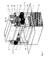
- FIG. 6 describes the embodiment of a four-point forming press having two groups of direct drive modules 2 aligned in the press longitudinal axis, each direct drive module 2 being mounted in a drive housing 27 positioned in the press transverse axis 19 .
- the drive housings 27 are secured via the press supports 28 to the press table 21 by means of tension rods 22 .
- the adjacent press supports 28 in the press longitudinal axis 1 are connected to one another using a transverse member 24 .
- the servomotors 7 are arranged in a mirror image between the direct drive modules 2 , the two adjacent servomotors 7 . 1 and 7 . 2 in each group being controlled in opposition to one another in order to compensate the transverse forces produced on the associated crank mechanisms 8 .
- FIG. 7 One drive system for a lower drive in a four-point forming press can be seen in FIG. 7 .
- Each two of four direct drive modules 2 aligned in press longitudinal axis 1 are mounted on a respective drive support 5 .
- the drive supports 5 are positioned transverse to the press longitudinal axis 1 .
- the pressing force in the crank mechanism 8 acts in the traction direction.
- the pressure points 12 connected to the connecting rods 23 act on the pressure point frames 15 that are arranged in the upper area of the slide 3 and that project into the upper clearance of the drive supports 5 .
- This compact construction provides a particularly low structural height for the press system.
- drive supports 5 in one case may be connected to the table 2 either monolithically or by means of tension rods 22 .
- the drive supports 5 are each divided into a drive housing 27 and associated press supports 28 that are jointly connected to the table 2 by means of tension rods 22 .
- the drive supports 5 are situated adjacent the space 16 which has as its upper extremity the tool mounting surface of the slide and as its lateral extremities innermost edges of vertical, upright supports, such as the legs of the monolithic body or the press supports 28 , supporting the drive supports 5 and which innermost edges are vertical projections of innermost extremities of the drive supports 5 .
- Allocated to all of the direct drive modules 2 are servomotors 7 with which it is possible to achieve flexible path and speed profiles for the movement of the slide 3 , the target positions of the slide 3 preferably being produced using guide wave-controlled electronic cams.
- a 360° circular movement, a reversing movement at an angle ⁇ 360° that passes through the bottom reverse point, or a movement at an angle ⁇ 180° that reverses in the area of the bottom reverse point may be selected.
- the latter mode may preferably be used in conjunction with the tilt regulation of the slide 3 that is possible with electronic synchronization of the pressure points 12 , in one plane for a two-point forming press or in two planes for a four-point forming press.
Landscapes
- Engineering & Computer Science (AREA)
- Mechanical Engineering (AREA)
- Press Drives And Press Lines (AREA)
- Control Of Presses (AREA)
Abstract
Description
Claims (19)
Applications Claiming Priority (4)
| Application Number | Priority Date | Filing Date | Title |
|---|---|---|---|
| DE102008034971 | 2008-07-25 | ||
| DE102008034971.2 | 2008-07-25 | ||
| DE200810034971 DE102008034971A1 (en) | 2008-07-25 | 2008-07-25 | Drive system of a forming press |
| PCT/DE2009/000913 WO2010009694A2 (en) | 2008-07-25 | 2009-06-29 | Drive system for a forming press |
Publications (2)
| Publication Number | Publication Date |
|---|---|
| US20110126649A1 US20110126649A1 (en) | 2011-06-02 |
| US8910569B2 true US8910569B2 (en) | 2014-12-16 |
Family
ID=41152163
Family Applications (1)
| Application Number | Title | Priority Date | Filing Date |
|---|---|---|---|
| US13/055,862 Expired - Fee Related US8910569B2 (en) | 2008-07-25 | 2009-06-29 | Drive system for a forming press |
Country Status (6)
| Country | Link |
|---|---|
| US (1) | US8910569B2 (en) |
| EP (1) | EP2321119B8 (en) |
| CN (1) | CN102105298B (en) |
| DE (1) | DE102008034971A1 (en) |
| PL (1) | PL2321119T3 (en) |
| WO (1) | WO2010009694A2 (en) |
Families Citing this family (21)
| Publication number | Priority date | Publication date | Assignee | Title |
|---|---|---|---|---|
| DE102008034971A1 (en) * | 2008-07-25 | 2010-01-28 | Müller Weingarten AG | Drive system of a forming press |
| DE102009035215A1 (en) * | 2009-07-29 | 2011-02-10 | Dieffenbacher Gmbh + Co. Kg | Press with a directly driven crank mechanism |
| DE102009035214A1 (en) * | 2009-07-29 | 2011-02-24 | Dieffenbacher Gmbh + Co. Kg | Press with a directly driven crank mechanism |
| DE102009051939A1 (en) * | 2009-11-04 | 2011-05-05 | Dieffenbacher Gmbh + Co. Kg | Press with a directly driven crank mechanism, press line of such presses and a method for producing a press with at least one direct drive. |
| DE102009051876A1 (en) * | 2009-11-04 | 2011-05-05 | Dieffenbacher Gmbh + Co. Kg | Press with a directly driven crank mechanism |
| DE102009055739B4 (en) * | 2009-11-26 | 2021-01-14 | Langenstein & Schemann Gmbh | Forming machine, especially servo press |
| JP5301500B2 (en) * | 2010-05-28 | 2013-09-25 | アイダエンジニアリング株式会社 | Servo press machine driven by multiple motors |
| DE102010054976A1 (en) * | 2010-06-07 | 2011-12-08 | Kiefel Gmbh | Thermoforming station, thermoforming machine, molding or stamping method, and manufactured articles |
| DE102010031100B4 (en) | 2010-07-08 | 2017-09-14 | Zeulenroda Presstechnik Gmbh | Forming press with direct drive by segment motors |
| DE102010031107B4 (en) | 2010-07-08 | 2013-11-21 | Raster-Zeulenroda Werkzeugmaschinen Gmbh | Forming press with a ram direct drive |
| DE102010060627B4 (en) * | 2010-11-17 | 2020-11-05 | Langenstein & Schemann Gmbh | Forming machine with slide control |
| CN102285135A (en) * | 2011-07-21 | 2011-12-21 | 宁波精达成形装备股份有限公司 | Double-side driving and four-point force-applying press machine |
| DE102011113624B4 (en) | 2011-09-16 | 2015-07-30 | Fraunhofer-Gesellschaft zur Förderung der angewandten Forschung e.V. | Modular drive system for a forming machine |
| EP2666727B1 (en) | 2012-05-24 | 2016-09-07 | MULTIVAC Sepp Haggenmüller SE & Co. KG | Lifting device for a packing machine |
| JP2016515048A (en) * | 2013-03-12 | 2016-05-26 | ヴァムコ・インターナショナル・インコーポレイテッド | Press machine |
| DE102013021300C5 (en) * | 2013-12-19 | 2018-11-22 | Jörg von Seggern Maschinenbau GmbH | Lifting device for a tool |
| DE102014115238B4 (en) | 2014-10-20 | 2017-02-02 | Schuler Pressen Gmbh | Press drive device for a press and press with press drive device |
| DE102014115241B4 (en) | 2014-10-20 | 2021-08-12 | Schuler Pressen Gmbh | Press drive device for a press and press with press drive device |
| DE102014115240B4 (en) | 2014-10-20 | 2017-08-24 | Schuler Pressen Gmbh | Press drive device for a press and press with press drive device |
| MX2018006187A (en) * | 2015-11-20 | 2018-08-01 | Sms Group Gmbh | Path-controlled press having a sliding block. |
| CN106891561B (en) * | 2017-04-28 | 2019-08-06 | 扬力集团股份有限公司 | It is a kind of for processing four point pressure machines of air-conditioner fin |
Citations (13)
| Publication number | Priority date | Publication date | Assignee | Title |
|---|---|---|---|---|
| US4014232A (en) * | 1974-10-31 | 1977-03-29 | Clevepak Corporation | Die-set assembly |
| US6067886A (en) * | 1996-08-02 | 2000-05-30 | The Vision Limited Partnership | Machine trim press having counterbalance features |
| JP2000288792A (en) | 1999-04-06 | 2000-10-17 | Amada Co Ltd | Press working machine |
| EP1082185A1 (en) | 1998-05-12 | 2001-03-14 | Johannes Hülshorst | A deep drawing press with a ram hammer and drawing cushion driven by threaded spindles and spindle nuts |
| US6595125B2 (en) * | 2001-04-25 | 2003-07-22 | Komatsu, Ltd. | Slide drive unit of a press |
| WO2004056559A1 (en) | 2002-12-19 | 2004-07-08 | Siemens Aktiengesellschaft | Pressing device |
| DE102004009256A1 (en) | 2004-02-26 | 2005-09-15 | Schuler Pressen Gmbh & Co. Kg | Mechanical multi-servo press |
| WO2006045279A2 (en) | 2004-10-25 | 2006-05-04 | Müller Weingarten AG | Drive system for a forming press |
| US7143617B2 (en) * | 2002-02-14 | 2006-12-05 | Institute Of Technology Precision Electrical Discharge Work's | Press |
| US7165437B2 (en) * | 2004-01-08 | 2007-01-23 | Kojima Iron Works Co., Ltd. | Mechanical press device |
| DE102007026727A1 (en) | 2006-06-08 | 2007-12-13 | Müller Weingarten AG | Drive system of a forming press |
| US7516695B2 (en) * | 2005-03-16 | 2009-04-14 | Komatsu Ltd. | Press machine |
| US20110126649A1 (en) * | 2008-07-25 | 2011-06-02 | Uwe Darr | Drive system for a forming press |
Family Cites Families (2)
| Publication number | Priority date | Publication date | Assignee | Title |
|---|---|---|---|---|
| JP2003320484A (en) * | 2002-05-01 | 2003-11-11 | Murata Mach Ltd | Motor driven type link press |
| DE102004052007B4 (en) | 2004-10-25 | 2007-12-06 | Müller Weingarten AG | Drive system of a forming press |
-
2008
- 2008-07-25 DE DE200810034971 patent/DE102008034971A1/en not_active Withdrawn
-
2009
- 2009-06-29 PL PL09775925T patent/PL2321119T3/en unknown
- 2009-06-29 US US13/055,862 patent/US8910569B2/en not_active Expired - Fee Related
- 2009-06-29 WO PCT/DE2009/000913 patent/WO2010009694A2/en active Application Filing
- 2009-06-29 EP EP09775925.2A patent/EP2321119B8/en active Active
- 2009-06-29 CN CN200980129632.5A patent/CN102105298B/en not_active Expired - Fee Related
Patent Citations (17)
| Publication number | Priority date | Publication date | Assignee | Title |
|---|---|---|---|---|
| US4014232A (en) * | 1974-10-31 | 1977-03-29 | Clevepak Corporation | Die-set assembly |
| US6067886A (en) * | 1996-08-02 | 2000-05-30 | The Vision Limited Partnership | Machine trim press having counterbalance features |
| EP1082185A1 (en) | 1998-05-12 | 2001-03-14 | Johannes Hülshorst | A deep drawing press with a ram hammer and drawing cushion driven by threaded spindles and spindle nuts |
| JP2000288792A (en) | 1999-04-06 | 2000-10-17 | Amada Co Ltd | Press working machine |
| US6595125B2 (en) * | 2001-04-25 | 2003-07-22 | Komatsu, Ltd. | Slide drive unit of a press |
| US7143617B2 (en) * | 2002-02-14 | 2006-12-05 | Institute Of Technology Precision Electrical Discharge Work's | Press |
| WO2004056559A1 (en) | 2002-12-19 | 2004-07-08 | Siemens Aktiengesellschaft | Pressing device |
| US7165437B2 (en) * | 2004-01-08 | 2007-01-23 | Kojima Iron Works Co., Ltd. | Mechanical press device |
| US7102316B2 (en) * | 2004-02-26 | 2006-09-05 | Schuler Pressen Gmbh & Kg | Mechanical press |
| DE102004009256A1 (en) | 2004-02-26 | 2005-09-15 | Schuler Pressen Gmbh & Co. Kg | Mechanical multi-servo press |
| WO2006045279A2 (en) | 2004-10-25 | 2006-05-04 | Müller Weingarten AG | Drive system for a forming press |
| US7516695B2 (en) * | 2005-03-16 | 2009-04-14 | Komatsu Ltd. | Press machine |
| DE102007026727A1 (en) | 2006-06-08 | 2007-12-13 | Müller Weingarten AG | Drive system of a forming press |
| WO2007140765A2 (en) * | 2006-06-08 | 2007-12-13 | Müller Weingarten AG | Drive system of a forming press |
| US20090260460A1 (en) | 2006-06-08 | 2009-10-22 | Uwe Darr | Drive system of a forming press |
| US8549940B2 (en) * | 2006-06-08 | 2013-10-08 | Mueller Weingarten Ag | Drive system of a forming press |
| US20110126649A1 (en) * | 2008-07-25 | 2011-06-02 | Uwe Darr | Drive system for a forming press |
Also Published As
| Publication number | Publication date |
|---|---|
| EP2321119B1 (en) | 2018-07-18 |
| PL2321119T3 (en) | 2019-05-31 |
| US20110126649A1 (en) | 2011-06-02 |
| EP2321119B8 (en) | 2018-09-05 |
| EP2321119A2 (en) | 2011-05-18 |
| DE102008034971A1 (en) | 2010-01-28 |
| WO2010009694A3 (en) | 2010-05-14 |
| CN102105298B (en) | 2015-09-30 |
| WO2010009694A2 (en) | 2010-01-28 |
| CN102105298A (en) | 2011-06-22 |
Similar Documents
| Publication | Publication Date | Title |
|---|---|---|
| US8910569B2 (en) | Drive system for a forming press | |
| JP6016896B2 (en) | Machine tools in the form of presses for machining workpieces, especially metal sheets | |
| JP5649502B2 (en) | Multi-point servo press | |
| CN102156340B (en) | High-precision pose adjusting device for spliced grating | |
| CN105458732A (en) | Novel rack structure for sectional bar machining device | |
| CN103273329A (en) | Five-axis numerical control machine tool | |
| CN204321602U (en) | Five-axis vertical turn-milling complex machining center | |
| CN102172760B (en) | Crank-input multilink press driven by four servo motors in parallel | |
| JP2008503352A (en) | Die cushion device for drawing with a hybrid drive | |
| CN103170748A (en) | High-speed large-coverage laser cutting machine | |
| CN213185767U (en) | Split folding type electric cylinder | |
| CN201446737U (en) | Guide-rail precision adjusting mechanism of pressing machine tool | |
| US6510786B1 (en) | Hydromechanical press drive | |
| CN107088756A (en) | Three axis machining center for producing aluminium section bar | |
| CN102328448A (en) | Multi-connecting-rod mechanical press with driven by three parallel servo motor inputs | |
| JP4880956B2 (en) | Press drive device | |
| CN208226815U (en) | Rotor assembly machine | |
| CN207188529U (en) | A kind of mutual flow-through rear material stopping device for bending machine of integration | |
| CN206455101U (en) | Three axle pressing robots | |
| CN221092629U (en) | Turning device with aligning mechanism | |
| JP2923277B1 (en) | Transfer device of forging press machine | |
| CN107199271B (en) | For to workpiece, particularly to the processing unit and lathe of metal plate punch process | |
| CN114074451B (en) | Hot melt pressing device | |
| CN213496158U (en) | Multi-station high-strength steel hot forming press | |
| JP2002361552A (en) | High-speed grinding machine |
Legal Events
| Date | Code | Title | Description |
|---|---|---|---|
| AS | Assignment |
Owner name: MUELLER WEINGARTEN AG, GERMANY Free format text: ASSIGNMENT OF ASSIGNORS INTEREST;ASSIGNOR:DARR, UWE;REEL/FRAME:026161/0183 Effective date: 20110419 |
|
| STCF | Information on status: patent grant |
Free format text: PATENTED CASE |
|
| FEPP | Fee payment procedure |
Free format text: PAYOR NUMBER ASSIGNED (ORIGINAL EVENT CODE: ASPN); ENTITY STATUS OF PATENT OWNER: LARGE ENTITY |
|
| MAFP | Maintenance fee payment |
Free format text: PAYMENT OF MAINTENANCE FEE, 4TH YEAR, LARGE ENTITY (ORIGINAL EVENT CODE: M1551) Year of fee payment: 4 |
|
| FEPP | Fee payment procedure |
Free format text: MAINTENANCE FEE REMINDER MAILED (ORIGINAL EVENT CODE: REM.); ENTITY STATUS OF PATENT OWNER: LARGE ENTITY |
|
| LAPS | Lapse for failure to pay maintenance fees |
Free format text: PATENT EXPIRED FOR FAILURE TO PAY MAINTENANCE FEES (ORIGINAL EVENT CODE: EXP.); ENTITY STATUS OF PATENT OWNER: LARGE ENTITY |
|
| STCH | Information on status: patent discontinuation |
Free format text: PATENT EXPIRED DUE TO NONPAYMENT OF MAINTENANCE FEES UNDER 37 CFR 1.362 |
|
| FP | Lapsed due to failure to pay maintenance fee |
Effective date: 20221216 |