US8910486B2 - Expander for stirling engines and cryogenic coolers - Google Patents
Expander for stirling engines and cryogenic coolers Download PDFInfo
- Publication number
- US8910486B2 US8910486B2 US12/841,280 US84128010A US8910486B2 US 8910486 B2 US8910486 B2 US 8910486B2 US 84128010 A US84128010 A US 84128010A US 8910486 B2 US8910486 B2 US 8910486B2
- Authority
- US
- United States
- Prior art keywords
- expander
- displacer
- outer cylinder
- regenerator
- regenerator matrix
- Prior art date
- Legal status (The legal status is an assumption and is not a legal conclusion. Google has not performed a legal analysis and makes no representation as to the accuracy of the status listed.)
- Expired - Fee Related, expires
Links
Images


Classifications
-
- F—MECHANICAL ENGINEERING; LIGHTING; HEATING; WEAPONS; BLASTING
- F25—REFRIGERATION OR COOLING; COMBINED HEATING AND REFRIGERATION SYSTEMS; HEAT PUMP SYSTEMS; MANUFACTURE OR STORAGE OF ICE; LIQUEFACTION SOLIDIFICATION OF GASES
- F25B—REFRIGERATION MACHINES, PLANTS OR SYSTEMS; COMBINED HEATING AND REFRIGERATION SYSTEMS; HEAT PUMP SYSTEMS
- F25B9/00—Compression machines, plants or systems, in which the refrigerant is air or other gas of low boiling point
- F25B9/14—Compression machines, plants or systems, in which the refrigerant is air or other gas of low boiling point characterised by the cycle used, e.g. Stirling cycle
-
- F—MECHANICAL ENGINEERING; LIGHTING; HEATING; WEAPONS; BLASTING
- F02—COMBUSTION ENGINES; HOT-GAS OR COMBUSTION-PRODUCT ENGINE PLANTS
- F02G—HOT GAS OR COMBUSTION-PRODUCT POSITIVE-DISPLACEMENT ENGINE PLANTS; USE OF WASTE HEAT OF COMBUSTION ENGINES; NOT OTHERWISE PROVIDED FOR
- F02G2250/00—Special cycles or special engines
- F02G2250/31—Nano- or microengines
-
- F—MECHANICAL ENGINEERING; LIGHTING; HEATING; WEAPONS; BLASTING
- F25—REFRIGERATION OR COOLING; COMBINED HEATING AND REFRIGERATION SYSTEMS; HEAT PUMP SYSTEMS; MANUFACTURE OR STORAGE OF ICE; LIQUEFACTION SOLIDIFICATION OF GASES
- F25B—REFRIGERATION MACHINES, PLANTS OR SYSTEMS; COMBINED HEATING AND REFRIGERATION SYSTEMS; HEAT PUMP SYSTEMS
- F25B2309/00—Gas cycle refrigeration machines
- F25B2309/003—Gas cycle refrigeration machines characterised by construction or composition of the regenerator
Definitions
- This invention generally relates to improved miniaturized Stirling engines having efficient regenerator, displacer and cold finger designs suitable for used in cryogenic coolers.
- Conventional Stirling Cycle Rotary Cooling Engines generally have a compressor and an expander connected to a crank mechanism driven by an electrical motor.
- the compressor also known as a pressure wave generator. It is attached to the warm end of the expander and delivers acoustic power (compressor PV work) into the expander warm end inlet.
- Compressor PV work is the integration of the pressure-volume curve over one thermodynamic cycle or one complete revolution of the crank shaft.
- Compressor PV work has a unit of energy, and when derived over time, it is defined as acoustic power.
- the expander recovers this work at the cold end by causing the gas to expand and thus absorb heat from external power source such as an IR sensor.
- the gas expansion is achieved mechanically by placing the expander piston and compression piston at 90 deg mechanical phase to each other relative to the crank shaft.
- a working fluid typically a noble gas
- a working fluid is compressed at the warm end and is expanded at the cold end.
- At the distal tip of the expander coldwell when the expander piston is being pulled backward to iso-thermally expand the working gas, heat is absorbed from the load and very low temperatures are achieved due to efficient thermal isolation between the warm and cold end of the expander unit. Temperature can reach down to the cryogenic range, e.g., about 77° K.
- An infrared (IR) sensor which needs to operate at such low temperatures, is attached to the coldwell to be cooled.
- a conventional Stirling engine is described in U.S. Pat. Nos. 7,555,908 and 7,587,896 and references cited therein, which are incorporated herein by reference in their entireties. Stirling engines are commonly used as cryogenic coolers to cool IR sensors for IR cameras and the like.
- a conventional expander 1 illustrated in FIG. 1 , generally consists of cold finger 2 , which is a small diameter, thin-wall cylinder/tube, and a displacer unit 3 positioned in the cold finger.
- Displacer unit 3 comprises a canister tightly packed with metallic fine mesh, spheres or felt-like material, and moves within cold finger 2 .
- the metallic fine mesh, spheres or felt-like material is also known as the regenerator matrix and is designed to exchange thermal energy with the working fluid.
- Displacer unit 3 is slip fit into cold finger 2 to provide precise linear reciprocating motion between the cold finger and the displacer.
- Working gas from the warm end enters expander 1 at the proximal end of displacer unit 3 at inlet 4 .
- inlet 4 Since displacer unit 3 undergoes reciprocating motion, inlet 4 is static while inline with a moving slotted inlet machined into the displacer at the warm end clearance dynamic seal 5 and thus allows free flow into the regenerator regardless of its position.
- Reciprocating dynamic seals 5 prevent leakage of the working gas as it enters the moving displacer unit. Also, it prevents the cold gas present in the clearance between the displacer and the expander cylinder from escaping into to warm end during the expansion portion of the cycle.
- the working gas then enters the regenerator matrix to exchange thermal energy with the regenerator, and is pre-cooled.
- the working gas reaches the distal end of the displacer unit proximate to coldwell 6 ideally at the same temperature it left at the previous cycle right after the expansion.
- an IR sensor is attached to coldwell 6 to be cooled.
- displacer unit/canister 3 The reciprocating motion of displacer unit/canister 3 , more specifically the movement away from coldwell 6 , isothermally expands the working gas causing it to cool down and absorb heat from the thermal load. Subsequently the expander piston/displacer moves toward the end cap and forces the working gas to flow back toward the warm end through the regenerator matrix to exchange thermal energy therewith, and is warmed.
- displacer unit 3 functions both as a displacer and regenerator.
- Displacer unit 3 also functions as piston and thus performs the expansion process in the thermodynamic cycle.
- the design of such an expander in which the displacer unit performs three different functions, i.e., displacer, regenerator and expansion piston, requires the system engineer to perform trade offs among various system requirements which can be often conflicting.
- the need to provide thermal barrier/insulation between the warm end and the cold end favors the cold finger 2 be long, thin and have a small diameter, since heat conduction along tube 2 would be minimized.
- the demand for miniaturization and rigidity of expander 1 favors the opposite.
- One major challenge when attempting to reduce expander length is the need to maintain a predetermined surface area for a given mass flow rate and cooling capacity by the regenerator matrix.
- a regenerator used in a Stirling engine can be thought of as a one-way and a bidirectional heat exchanger in which thermal energy flows in and out of the matrix and to or from the working gas.
- the heat exchanging media i.e., the regenerator matrix
- the fine wire mesh is commonly obtained in a form of woven screen in a variety of wire sizes, weave structures, mesh density and materials.
- Other known types of regenerator matrices use spheres made of stainless steel, bronze, lead and erbium, among others.
- regenerator matrices usually have large thermal capacity, large surface area, low flow impedance, small void volume and large axial thermal resistance to achieve high regenerator effectiveness. Cooler performance is sensitive to regenerator effectiveness.
- a regenerator is considered to be “100% effective” when the temperature of the working fluid exiting the regenerator is equal to the temperature of working fluid entering it. When the temperature of the gas leaving the regenerator at the compressor end is colder than the entering gas, it indicates that not enough thermal energy was exchanged with the regenerator matrix. This causes the regenerator to be warmer than it could have been, thus reducing the pre-cooling of the incoming gas prior to it entering the expansion space. It is a challenge to minimize the length of the expander while maintaining efficient thermal exchange, i.e., adequate regenerator surface area, minimum pressure drop, large axial thermal resistance along the regenerator, large thermal capacitance and minimum weight.
- regenerator length L E shown in FIG. 1 is determined primarily by the regenerator length L R , while regenerator length L R is determined by expander 1 's need for large matrix surface area, regenerator tube thermal resistance, regenerator matrix thermal contact resistance and shuttle losses consideration. Satisfying these design constraints has resulted in a relatively long expander assembly length L E and thus limits the ability to miniaturize the overall cryogenic cooler.
- the invention is directed to an improved cryogenic cooler with an expander where the regenerator matrix is decoupled from the displacer or piston, thereby allowing the design of each to be optimized substantially independently.
- the regenerator matrix is preferably positioned spaced apart from the displacer and can be designed to enhance thermal exchanges and flow rates of the working gas, and to preferably maintain proper phase relationship between the mass flow rate and pressure inside the regenerator independent of displacer/expander piston length and diameter.
- the regenerator matrix has a serpentine shape or U-shape disposed around the cold finger and displacer/expander unit.
- the regenerator matrix in this embodiment is static.
- the inventive displacer serves only one purpose and it is to perform gas expansion operation and gas displacement. It does not have to contain within it the regenerator and thus its geometry and mechanical structure can take any shape and be optimized for maximum thermal insulation and mechanical flexibility/self alignment with cylinder bore with lower thermal conduction to minimize heat conduction loss along the displacer.
- the displacer can be a stiff hollow cylinder with a closed end proximate to the coldwell and made from a low thermal conductive, engineered plastic.
- the displacer can have a piston head proximate to the coldwell and a thin shaft or rod, which has a small diameter to minimize heat conduction loss.
- the thin shaft may have a flexural modulus that allows the displacer to self-correct to minimize frictional contacts with the cold finger which can generate heat.
- the invention is also directed to a cold finger that has a thermal effective length that is substantially longer than its physical or geometrical length.
- the cold finger comprises a plurality of tubes that are arranged in a concentric arrangement and are connected selectively to form a serpentine thermal path to reduce heat conduction loss. Stiffeners can be used with the plurality of tubes to enhance the structural integrity or stiffness of the cold finger.
- FIG. 1 is a cross-sectional view of a conventional Stirling engine expander unit
- FIG. 2A is a cross-sectional view of an expander, with a displacer omitted for clarity, according to one embodiment of the invention
- FIG. 2B is a cross-sectional view of the embodiment shown in FIG. 2A with the regeneration matrix decoupled from the displacer unit;
- FIG. 3 is a perspective view of the regenerator matrix shown in FIGS. 2A and 2B ;
- FIG. 4 is a side-by-side perspective view of an expander according to one embodiment of the invention and a conventional expander;
- FIG. 5 is a side-by-side perspective view of a cryogenic cooler according to one embodiment of the invention and a conventional cryogenic cooler;
- FIG. 6A is a cross-sectional view of an expander showing an alternative displacer according to one embodiment of the invention.
- FIG. 6B is a perspective view of the expander of FIG. 6A ;
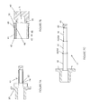
- FIG. 7A is a cross-sectional view of an expander showing a cold finger, with parts omitted for clarity, according to one embodiment of the invention.
- FIG. 7B is an enlarged view of the coldwell portion of FIG. 7A ;
- FIG. 7C shows the effective thermal length of the cold finger shown in FIGS. 7A and 7B ;
- FIG. 8A is a cross-sectional view of the expander of FIGS. 7A-7B with a stiffener
- FIG. 8B is an enlarged perspective view of the stiffener
- FIG. 9A is a cross-sectional view of a multi-tube displacer
- FIG. 9B is an enlarged view of the distal end of the displacer of FIG. 9A ;
- FIG. 9C is a cross-sectional view of the displacer of FIG. 9A with end cap and drive linkage.
- FIG. 9D shows the effective thermal length of the displacer shown in FIGS. 9A-9C .
- Embodiments of the invention are directed to an expander unit 10 , which is usable in a Stirling engine or in a cryogenic cooler for an IR camera.
- regenerator matrix 12 is decoupled from displacer unit 14 .
- Inventive regenerator matrix 12 is static, i.e., it does not move when displacer unit 14 undergoes reciprocating motion to displace the working gas in the Stirling thermodynamic cycle.
- Displacer unit 14 is connected (not shown) to displacer drive linkage 16 , which is connected to the Stirling engine's driving motor. Reciprocal motions by displacer 14 expand the working gas in expansion space 15 .
- regenerator matrix or regenerator 12 is placed outside the displacer 14 and inside a vacuumed Dewar enclosure (not shown), which includes Dewar adapter ring 18 .
- displacer unit 14 is a cylinder with a closed distal end that forms part of expansion space 15 .
- Displacer unit 14 is slidingly received in a cylindrical cold finger 17 , which is supported by cold-finger base 20 .
- Cold finger 17 extends from base 18 toward end cap heat exchanger 40 .
- the clearance between displacer unit 14 and cold finger 17 is preferably small to minimize or prevent the escape of working gas from expansion space 15 . Generally, this clearance is in the range of 0.0005 inch. However, this clearance is preferably sufficient to minimize the heat caused by the frictional contact between cold finger 17 and displacer 14 .
- regenerator matrix 12 is an assembly comprising multiple tubes 22 , which are connected to each other at their ends by connectors 24 to form U-shape interconnections or a serpentine path.
- regenerator matrix 12 is preferably arranged around and external to displacer 14 and cold finger 17 in a circular pattern. This arrangement allows for a linearly short and compact regenerator matrix with relatively long effective thermal length.
- warm working gas preferably at a room temperature of about 296° K, enters and exits expander 10 at port 26 and enters proximal opening 28 of regenerator 12 .
- the warm working gas exchanges thermal energy with, and is cooled by, regenerator 12 along the U-shape path formed by tubes 22 and connectors 24 .
- the working gas then exits regenerator 12 at distal opening 30 at the cryogenic temperature, e.g., about 77° K, if the thermal efficiency of the regenerator is 100%.
- the working gas then enters expansion space 15 .
- Displacer 14 then moves away from end cap heat exchanger 40 to expand, and thus cool, the working gas.
- An IR sensor, or other object to be cooled, attached to end cap heat exchanger 40 is chilled by this thermodynamic cycle. No working gas travels through displacer 14 .
- the cooled gas flows back through the heat exchanger in the end cap 40 into the regenerator tubes toward the compressor.
- the gas is cooled and pulled away from the end cap toward the displacer which houses the regenerator matrix.
- the inventor of the present invention discovered through tests and experiments that this inventive design provides faster cool down than the conventional design.
- the cold gas flows at high speed through end cap heat exchanger 40 which does not exist in the common design thereby providing improved heat lift or heat transfer from the end cap on which power is dissipated by the detector. Given the same cooling capacity, the inventive expander design will provide about 25% faster cool down than the conventional expanders.
- regenerator 12 As displacer 14 moves toward end cap heat exchanger 40 , the working gas is forced to flow back into distal opening 30 toward proximal opening 28 , where it exchanges thermal energy with regenerator 12 and is warmed.
- the thermal efficiency of regenerator 12 or expander 10 is 100%, the working gas exits proximal opening 28 at room temperature and back toward the compressor portion of the Stirling engine through port 26 .
- the thermal length of regenerator 12 is sufficient to achieve 100% thermal effectiveness.
- displacer 14 The reciprocal movement of displacer 14 is provided by its connection through drive linkage 16 and is supported by displacer guideway journal 32 and displacer guideway sleeve 34 .
- End cap 40 is provided above cold finger 17 to provide a path for the working gas from distal opening 30 at the end of regenerator 12 to expansion space 15 , and vice versa.
- End cap 40 also serves as a housing for a cold heat exchanger mesh.
- This heat exchanger mesh is made of high conductivity material to facilitate heat flow from the external heat load, such as the detector or IR sensor, into the cold working gas. This increases efficiency of the expander and the cryogenic cooler, provides faster cool down time, and represents improvements over conventional expanders.
- displacer 14 is constructed from a strong, lightweight material to minimize the vibration caused by sinusoidal motion at high speed.
- Displacer 14 should also have a low coefficient of conduction heat transfer to minimize the heat transfer by conduction in the longitudinal direction from the warm end or Dewar ring 18 to end cap heat exchanger 40 to minimize heat conduction loss.
- Suitable materials include polyphenylene sulfide (PPS) or PPS reinforced with fibers or fiberglass fibers, commercially available as Ryton® from Quadrant Extreme Materials.
- regenerator 12 as shown in FIG. 2A is static relative to expander 10 and inlet port 26 is static.
- a dynamic inlet such as moving gas inlet 4
- the design of the working gas inlet can be simplified, resulting in reduced PV power losses due to improved inlet seal, since there is generally a certain amount of leakage present with dynamic seals.
- the lack of a need to move the regenerator matrix during the thermodynamic cycle reduces vibration and noise due to lower moving mass.
- the novel regenerator design of this embodiment is significantly shorter linearly than conventional regenerator matrix 3 shown in FIG. 1 , and yet has a longer effective thermal length, which includes the thermal paths along the U-shape or serpentine path comprising tubes 22 and connectors 24 .
- This embodiment provides a longer thermal path, a higher thermal resistance, and a large regenerator matrix surface area, which lead to effective regenerator and efficient thermodynamic cycle.
- the use of low thermal conductivity materials and thin wall tubes for displacer unit 14 and cold finger 17 increases the thermal resistance and thus reduces heat leak toward expander 10 's end cap heat exchanger 40 .
- regenerator 12 is the additional cooling capacity resulting from lower thermal losses, which enables a reduction of the compressor size as well as the overall linear length of expander 10 .
- the relatively long effective thermal length of the combined tubes 22 of regenerator 12 allows for the use of coarser metal mesh or spheres to reduce pressure drop and maintaining adequate surface area for the regeneration process of the thermodynamic cycle.
- this embodiment optimizes regenerator design substantially independently of the design and requirements of displacer 14 and cold finger 17 , such as the total volume necessary to hold the regenerator material and the structural integrity of the cold finger which supports highly sensitive optical electronics sensors, e.g., IR detectors.
- regenerator length thermal resistance and surface area
- expander length cold finger structural stiffness
- both the regenerator 3 and displacer 2 are supported by the cold-finger and their reciprocal movements cause a low natural bending frequency. These frequencies often cause end cap heat exchanger 40 , which supports the IR sensors, to vibrate, further leading the IR sensors to experience significant movements and a decrease the quality of the thermal images.
- the regenerator By decoupling regenerator 12 from displacer unit 14 , the regenerator, generally the heaviest component of expander 10 , is kept static. Keeping the regenerator 12 static as described above provides an advantage by obviating this self-induced vibration and the low natural bending frequency.
- regenerator 12 decoupled from the displacer unit, additional room or space is available to strengthen displacer 14 , e.g., by stiffening the displacer and reducing unwanted movements or vibrations.
- regenerator 12 in place of conventional regenerator 1 results in a significant reduction in the length of the expander.
- expander 10 shown on the left is about 47% shorter than conventional expander 1 shown on the right.
- the length of expander 10 is about 1.00 inch from the Dewar ring to its tip, as compared to the 1.89 inch length of conventional expander 1 .
- a conventional cryogenic cooler shown on the right using conventional expander 1 would fit in a circular envelope having a radius of about 4.125 inch, while an embodiment of a cryogenic cooler shown on the left using expander 10 can fit into an envelope with a diameter of about 2.62 inch.
- the reduced volume is about one-fourth of the volume of the conventional cryogenic cooler, since the reduction in volume is the cube of the radius and the reduction in surface area is the square of the radius.
- regenerator 12 comprises a single thick-wall hollow cylindrical member that is positioned around cold finger 17 and displacer 14 .
- a serpentine path comprising metal mesh or spheres similar to those discussed above with proximal and distal openings 28 and 30 is provided to exchange thermal energy with the working gas.
- a single piece regenerator may simplify the manufacturing process. Embodiments of the invention are not limited to any particular shape of the regenerator.
- displacer 14 comprises piston head 36 and shaft 38 , as shown in FIG. 6A .
- Piston head 36 forms a part of expansion space 15 and shaft 38 preferably has a diameter smaller than the diameter of piston head 36 in order to minimize heat conduction and heat loss to the coldwell.
- shaft 38 is flexible so that it can self-correct any misalignment between piston head 36 and cold finger 17 . Misalignments cause frictional contacts or rubbing, which produces heat and lowers the efficiency of the expander.
- the flexural modulus of shaft 38 is about one order of magnitude of the flexural modulus of the regenerator matrix, resulting in improved about an order of magnitude less frictional contact than conventional displacer/canister 3 .
- expander 10 may operate with smaller operational clearance with better seal.
- cold finger 17 is constructed from a plurality of concentric tubes that are attached to each other in a heads-and-tails fashion, as shown in FIGS. 7A and 7B .
- Cold finger 17 provides structural support for the IR detector, thermal barrier between the warm end and the cold end, and expansion volume.
- Cold finger 17 also forms a cylinder/guide way for displacer 14 , as it reciprocates.
- cold finger 17 has enhanced structural integrity to support the IR detector and enhanced thermal conduction resistance, while minimizing its length to support miniaturization.
- cold finger 17 is made of three tubes 42 , 44 , 46 which are successively smaller and are welded “heads and tails” inside each other in a concentric geometry.
- cold finger 17 is not limited to any particular number of tubes.
- the first and largest diameter outer tube 42 is the primary tube and is an integral part of the cold finger base 20 for structural integrity.
- primary outer tube 42 can be threadedly connected to cold finger base 20 .
- Middle tube 44 is inserted into the primary outer tube and welded, preferably laser welded, at the top, as best shown in FIG. 7B .
- Preferably primary outer tube 42 has enlarged head 48 and middle tube 44 has enlarged head 50 to provide a relatively larger surface for the weld.
- Inner tube 46 is welded to middle tube 44 at the bottom and extends out into the Dewar vacuum space and is attached, welded and sealed to end cap 40 , thus forming expansion space 15 .
- middle tube 44 has an enlarged head 52 which is welded to an enlarged head 54 of inner tube 46
- inner tube 46 has an enlarged head 56 to be attached to cap 40 .
- the primary heat transfer mechanism is heat conduction, which is limited to the path along primary tube 42 , weld joint 48 / 50 , middle tube 44 , weld joint 52 / 54 , inner tube 46 and joint 56 /end cap 40 . If fully extended, this thermal conduction path shown in FIG. 7C is significantly longer than the physical or geometrical length shown FIG. 7A . This reduction in heat conduction loss translates into an increase in cooling capacity, which can be traded for a smaller size compressor and motor for the Stirling engine and cryogenic cooler.
- tubes 42 , 44 , 46 may have insulated spacers or stiffeners between them to minimize vibrations which may cause movements of the IR detector attached to end cap heat exchanger 40 . These spacers may be discrete or may cover a circumference of one or more tubes.
- a thin wall flexure stiffener 58 is attached preferably by welding to primary outer tube 42 , which is attached directly to cold finger base 20 to provide optionally additional support, as shown in FIGS. 8A and 8B .
- stiffener 58 is made from titanium or other metals. Stiffener 58 is preferably thin to lower its thermal capacity and heat transferability and is spot welded at few spots to minimize heat leak.
- the multi concentric tube structure of cold finger 17 can also be applied to the design of displacer 14 , as shown in FIGS. 9A-9D .
- displacer 14 comprises outer tube 60 , middle tube 62 and inner tube 64 .
- outer tube 60 has enlarged head 66 which is welded to enlarged head 68 of middle tube 62 at the distal end of displacer 14 .
- Middle tube 62 is connected preferably by welding at the proximal end via its enlarged head 70 and enlarged head 72 of inner tube 64 .
- Inner tube 64 is connected at enlarged head 74 to end 76 .
- End 76 is the distal end of displacer 14 , which as discussed above forms a part of the expansion space.
- the conductive thermal length of displacer 14 is significantly longer than its geometrical length best shown in FIG. 9C .
- displacer 14 comprises rod 38 and piston head 36 , where rod 38 has a small diameter compared to conventional expander 1 when displacer 3 carries the regenerator matrix therewithin. Furthermore, the clearance between cold finger 17 and piston head 36 is relatively larger.
- the displacer is hollow to reduce its effective diameter and is made from PPS which has a low K value.
- the displacer comprises a thin shaft to reduce its diameter.
- the effective thermal length L of cold finger 17 is extended with using multiple concentric tubes connected in a heads-and-tails fashion.
- the flow/leak is most sensitive to the clearance h since it is to the power of 3 and thus leak can be reduced and thermodynamic losses as well. As discussed in the preceding paragraph, the embodiment of FIG. 6A reduces this heat loss due to pumping action.
Landscapes
- Engineering & Computer Science (AREA)
- Physics & Mathematics (AREA)
- Mechanical Engineering (AREA)
- Thermal Sciences (AREA)
- General Engineering & Computer Science (AREA)
- Heat-Exchange Devices With Radiators And Conduit Assemblies (AREA)
- Radiation Pyrometers (AREA)
Abstract
Description
where:
Q c =π·d 2·0.25·K/L,
where:
where:
Claims (18)
Priority Applications (2)
| Application Number | Priority Date | Filing Date | Title |
|---|---|---|---|
| US12/841,280 US8910486B2 (en) | 2010-07-22 | 2010-07-22 | Expander for stirling engines and cryogenic coolers |
| PCT/US2011/045118 WO2012012785A1 (en) | 2010-07-22 | 2011-07-22 | Expander for stirling engines and cryogenic coolers |
Applications Claiming Priority (1)
| Application Number | Priority Date | Filing Date | Title |
|---|---|---|---|
| US12/841,280 US8910486B2 (en) | 2010-07-22 | 2010-07-22 | Expander for stirling engines and cryogenic coolers |
Publications (2)
| Publication Number | Publication Date |
|---|---|
| US20120017607A1 US20120017607A1 (en) | 2012-01-26 |
| US8910486B2 true US8910486B2 (en) | 2014-12-16 |
Family
ID=44511795
Family Applications (1)
| Application Number | Title | Priority Date | Filing Date |
|---|---|---|---|
| US12/841,280 Expired - Fee Related US8910486B2 (en) | 2010-07-22 | 2010-07-22 | Expander for stirling engines and cryogenic coolers |
Country Status (2)
| Country | Link |
|---|---|
| US (1) | US8910486B2 (en) |
| WO (1) | WO2012012785A1 (en) |
Cited By (4)
| Publication number | Priority date | Publication date | Assignee | Title |
|---|---|---|---|---|
| US20160061382A1 (en) * | 2013-04-17 | 2016-03-03 | Siemens Plc | Improved thermal contact between cryogenic refrigerators and cooled components |
| US20160078987A1 (en) * | 2013-04-24 | 2016-03-17 | Siemens Plc | An assembly comprising a two-stage cryogenic refrigerator and associated mounting arrangement |
| WO2021019527A1 (en) * | 2019-07-29 | 2021-02-04 | Cryo Tech Ltd. | Cryogenic stirling refrigerator with a pneumatic expander |
| US20240077246A1 (en) * | 2022-09-06 | 2024-03-07 | L3Harris Technologies, Inc. | High efficiency cold finger |
Families Citing this family (9)
| Publication number | Priority date | Publication date | Assignee | Title |
|---|---|---|---|---|
| US8227928B2 (en) * | 2009-07-31 | 2012-07-24 | Palo Alto Research Center Incorporated | Thermo-electro-acoustic engine and method of using same |
| US9574797B2 (en) * | 2011-08-02 | 2017-02-21 | Flir Systems, Inc. | Stirling engine displacer drive |
| DE112012006734B4 (en) | 2012-07-26 | 2024-11-07 | Sumitomo (Shi) Cryogenics Of America, Inc. | Brayton circular engine |
| FR3008825B1 (en) * | 2013-07-18 | 2016-12-09 | Soc Francaise De Detecteurs Infrarouges - Sofradir | IMPROVED COLD FINGER AND DETECTION DEVICE COMPRISING THE COLD FINGER |
| US11137181B2 (en) | 2015-06-03 | 2021-10-05 | Sumitomo (Shi) Cryogenic Of America, Inc. | Gas balanced engine with buffer |
| US10082319B2 (en) * | 2015-10-15 | 2018-09-25 | Raytheon Company | Joule Thomson aided Stirling cycle cooler |
| FR3046880B1 (en) * | 2016-01-20 | 2018-02-23 | Lynred | COOLING DEVICE HAVING IMPROVED COLD FINGER |
| CN108061398A (en) * | 2017-12-29 | 2018-05-22 | 陕西仙童科技有限公司 | A kind of expanding machine and its segmented regenerator |
| CN110736263B (en) * | 2019-11-06 | 2025-07-22 | 上海理工大学 | Split Stirling expander |
Citations (52)
| Publication number | Priority date | Publication date | Assignee | Title |
|---|---|---|---|---|
| US3074244A (en) | 1961-04-12 | 1963-01-22 | Malaker Lab Inc | Miniature cryogenic engine |
| US3537516A (en) * | 1968-07-02 | 1970-11-03 | Olin Corp | Compact heat exchange component |
| US3742719A (en) | 1972-03-16 | 1973-07-03 | Hughes Aircraft Co | Cryogenic refrigerator |
| US4019336A (en) * | 1973-09-11 | 1977-04-26 | U.S. Philips Corporation | Refrigerator |
| US4024727A (en) | 1974-03-01 | 1977-05-24 | Hughes Aircraft Company | Vuilleumier refrigerator with separate pneumatically operated cold displacer |
| US4231418A (en) | 1979-05-07 | 1980-11-04 | Hughes Aircraft Company | Cryogenic regenerator |
| US4291547A (en) | 1978-04-10 | 1981-09-29 | Hughes Aircraft Company | Screw compressor-expander cryogenic system |
| US4310337A (en) * | 1979-10-29 | 1982-01-12 | Oerlikon-Buhrle U.S.A. Inc. | Cryogenic apparatus |
| US4365982A (en) | 1981-12-30 | 1982-12-28 | The United States Of America As Represented By The Secretary Of The Army | Cryogenic refrigerator |
| US4475346A (en) | 1982-12-06 | 1984-10-09 | Helix Technology Corporation | Refrigeration system with linear motor trimming of displacer movement |
| US4505119A (en) | 1982-12-09 | 1985-03-19 | Nachman Pundak | Flexible linkage for the displacer assembly in cryogenic coolers |
| US4514987A (en) | 1982-05-25 | 1985-05-07 | Ricor Ltd. | Passive automatic phase delay control of the displacer motion in pneumatically driven split cycle type cryocoolers |
| US4550571A (en) | 1983-12-28 | 1985-11-05 | Helix Technology Corporation | Balanced integral Stirling cryogenic refrigerator |
| US4574591A (en) | 1983-08-29 | 1986-03-11 | Helix Technology Corporation | Clearance seals and piston for cryogenic refrigerator compressors |
| US4588026A (en) | 1979-06-11 | 1986-05-13 | Raytheon Company | Coiled heat exchanger |
| US4619112A (en) | 1985-10-29 | 1986-10-28 | Colgate Thermodynamics Co. | Stirling cycle machine |
| US4711650A (en) | 1986-09-04 | 1987-12-08 | Raytheon Company | Seal-less cryogenic expander |
| US4846861A (en) | 1988-05-06 | 1989-07-11 | Hughes Aircraft Company | Cryogenic refrigerator having a regenerator with primary and secondary flow paths |
| US4858442A (en) | 1988-04-29 | 1989-08-22 | Inframetrics, Incorporated | Miniature integral stirling cryocooler |
| US4862695A (en) | 1986-11-05 | 1989-09-05 | Ice Cryogenic Engineering Ltd. | Split sterling cryogenic cooler |
| US4922722A (en) | 1988-05-24 | 1990-05-08 | Mitsubishi Denki Kabushiki Kaisha | Stirling refrigerator with nonlinear braking spring |
| US4967558A (en) | 1989-07-27 | 1990-11-06 | Stirling Technology Company | Stabilized free-piston stirling cycle machine |
| US5076058A (en) | 1990-07-27 | 1991-12-31 | Stirling Technology Company | Heat transfer head for a Stirling cycle machine |
| US5113663A (en) * | 1991-03-11 | 1992-05-19 | Cryomech, Inc. | Multi-stage cryogenic refrigerator |
| JPH04236068A (en) | 1991-01-11 | 1992-08-25 | Mitsubishi Electric Corp | Cryogenic refrigerating machine |
| US5197295A (en) | 1991-11-04 | 1993-03-30 | Nachman Pundak | Stirling miniature integral cooler/dewar assembly |
| US5535593A (en) | 1994-08-22 | 1996-07-16 | Hughes Electronics | Apparatus and method for temperature control of a cryocooler by adjusting the compressor piston stroke amplitude |
| US5596875A (en) | 1995-08-10 | 1997-01-28 | Hughes Aircraft Co | Split stirling cycle cryogenic cooler with spring-assisted expander |
| US5613365A (en) | 1994-12-12 | 1997-03-25 | Hughes Electronics | Concentric pulse tube expander |
| US5647219A (en) * | 1996-06-24 | 1997-07-15 | Hughes Electronics | Cooling system using a pulse-tube expander |
| US5680768A (en) * | 1996-01-24 | 1997-10-28 | Hughes Electronics | Concentric pulse tube expander with vacuum insulator |
| EP0803687A1 (en) | 1996-04-23 | 1997-10-29 | Cryotechnologies | Cryostat for cryogenic refrigerator and refrigerators comprising such a cryostat |
| US5822994A (en) | 1997-02-05 | 1998-10-20 | Litton Systems, Inc. | Low friction linear clearance seal |
| US6070414A (en) | 1998-04-03 | 2000-06-06 | Raytheon Company | Cryogenic cooler with mechanically-flexible thermal interface |
| JP2000292022A (en) | 1999-04-02 | 2000-10-20 | Fuji Electric Co Ltd | Gas cycle engine refrigerator |
| US6156970A (en) * | 1998-03-19 | 2000-12-05 | Harting Kgaa | Casing for housing electrical and/or electronic components |
| US20040231340A1 (en) * | 2003-05-23 | 2004-11-25 | Uri Bin-Nun | Low cost high performance laminate matrix |
| DE102004060819B3 (en) | 2004-11-29 | 2006-04-13 | Öko-Haustechnik inVENTer GmbH | Low temperature air conditioning system, working on the Stirling principle, has working cylinders and regenerators integrated into a block with heat exchangers at the cold and hot sides in a folded gamma configuration |
| US20060144054A1 (en) | 2005-01-04 | 2006-07-06 | Sumitomo Heavy Industries, Ltd. & Shi-Apd Cryogenics, Inc. | Co-axial multi-stage pulse tube for helium recondensation |
| US20060174635A1 (en) | 2005-02-04 | 2006-08-10 | Mingyao Xu | Multi-stage pulse tube with matched temperature profiles |
| US7137259B2 (en) | 2003-12-05 | 2006-11-21 | Superconductor Technologies Inc. | Cryocooler housing assembly apparatus and method |
| CN1975289A (en) | 2006-12-21 | 2007-06-06 | 浙江大学 | Multicylinder high-frequency vascular refrigerator |
| US20070204610A1 (en) | 2006-03-06 | 2007-09-06 | Tokyo Electron Limited | Cooling/heating apparatus and mounting apparatus |
| US20070261416A1 (en) | 2006-05-11 | 2007-11-15 | Raytheon Company | Hybrid cryocooler with multiple passive stages |
| US20070261418A1 (en) * | 2006-05-12 | 2007-11-15 | Flir Systems Inc. | Miniaturized gas refrigeration device with two or more thermal regenerator sections |
| US20070261419A1 (en) * | 2006-05-12 | 2007-11-15 | Flir Systems Inc. | Folded cryocooler design |
| US7296418B2 (en) | 2005-01-19 | 2007-11-20 | Raytheon Company | Multi-stage cryocooler with concentric second stage |
| US7350363B2 (en) | 2001-10-19 | 2008-04-01 | Siemens Magnet Technology, Ltd. | Pulse tube refrigerator sleeve |
| US7415830B2 (en) | 2005-08-31 | 2008-08-26 | Raytheon Company | Method and system for cryogenic cooling |
| US7555908B2 (en) | 2006-05-12 | 2009-07-07 | Flir Systems, Inc. | Cable drive mechanism for self tuning refrigeration gas expander |
| US20090193966A1 (en) * | 2008-02-06 | 2009-08-06 | Gm Global Technology Operations, Inc. | Compressor Piston |
| US7587896B2 (en) | 2006-05-12 | 2009-09-15 | Flir Systems, Inc. | Cooled infrared sensor assembly with compact configuration |
-
2010
- 2010-07-22 US US12/841,280 patent/US8910486B2/en not_active Expired - Fee Related
-
2011
- 2011-07-22 WO PCT/US2011/045118 patent/WO2012012785A1/en not_active Ceased
Patent Citations (52)
| Publication number | Priority date | Publication date | Assignee | Title |
|---|---|---|---|---|
| US3074244A (en) | 1961-04-12 | 1963-01-22 | Malaker Lab Inc | Miniature cryogenic engine |
| US3537516A (en) * | 1968-07-02 | 1970-11-03 | Olin Corp | Compact heat exchange component |
| US3742719A (en) | 1972-03-16 | 1973-07-03 | Hughes Aircraft Co | Cryogenic refrigerator |
| US4019336A (en) * | 1973-09-11 | 1977-04-26 | U.S. Philips Corporation | Refrigerator |
| US4024727A (en) | 1974-03-01 | 1977-05-24 | Hughes Aircraft Company | Vuilleumier refrigerator with separate pneumatically operated cold displacer |
| US4291547A (en) | 1978-04-10 | 1981-09-29 | Hughes Aircraft Company | Screw compressor-expander cryogenic system |
| US4231418A (en) | 1979-05-07 | 1980-11-04 | Hughes Aircraft Company | Cryogenic regenerator |
| US4588026A (en) | 1979-06-11 | 1986-05-13 | Raytheon Company | Coiled heat exchanger |
| US4310337A (en) * | 1979-10-29 | 1982-01-12 | Oerlikon-Buhrle U.S.A. Inc. | Cryogenic apparatus |
| US4365982A (en) | 1981-12-30 | 1982-12-28 | The United States Of America As Represented By The Secretary Of The Army | Cryogenic refrigerator |
| US4514987A (en) | 1982-05-25 | 1985-05-07 | Ricor Ltd. | Passive automatic phase delay control of the displacer motion in pneumatically driven split cycle type cryocoolers |
| US4475346A (en) | 1982-12-06 | 1984-10-09 | Helix Technology Corporation | Refrigeration system with linear motor trimming of displacer movement |
| US4505119A (en) | 1982-12-09 | 1985-03-19 | Nachman Pundak | Flexible linkage for the displacer assembly in cryogenic coolers |
| US4574591A (en) | 1983-08-29 | 1986-03-11 | Helix Technology Corporation | Clearance seals and piston for cryogenic refrigerator compressors |
| US4550571A (en) | 1983-12-28 | 1985-11-05 | Helix Technology Corporation | Balanced integral Stirling cryogenic refrigerator |
| US4619112A (en) | 1985-10-29 | 1986-10-28 | Colgate Thermodynamics Co. | Stirling cycle machine |
| US4711650A (en) | 1986-09-04 | 1987-12-08 | Raytheon Company | Seal-less cryogenic expander |
| US4862695A (en) | 1986-11-05 | 1989-09-05 | Ice Cryogenic Engineering Ltd. | Split sterling cryogenic cooler |
| US4858442A (en) | 1988-04-29 | 1989-08-22 | Inframetrics, Incorporated | Miniature integral stirling cryocooler |
| US4846861A (en) | 1988-05-06 | 1989-07-11 | Hughes Aircraft Company | Cryogenic refrigerator having a regenerator with primary and secondary flow paths |
| US4922722A (en) | 1988-05-24 | 1990-05-08 | Mitsubishi Denki Kabushiki Kaisha | Stirling refrigerator with nonlinear braking spring |
| US4967558A (en) | 1989-07-27 | 1990-11-06 | Stirling Technology Company | Stabilized free-piston stirling cycle machine |
| US5076058A (en) | 1990-07-27 | 1991-12-31 | Stirling Technology Company | Heat transfer head for a Stirling cycle machine |
| JPH04236068A (en) | 1991-01-11 | 1992-08-25 | Mitsubishi Electric Corp | Cryogenic refrigerating machine |
| US5113663A (en) * | 1991-03-11 | 1992-05-19 | Cryomech, Inc. | Multi-stage cryogenic refrigerator |
| US5197295A (en) | 1991-11-04 | 1993-03-30 | Nachman Pundak | Stirling miniature integral cooler/dewar assembly |
| US5535593A (en) | 1994-08-22 | 1996-07-16 | Hughes Electronics | Apparatus and method for temperature control of a cryocooler by adjusting the compressor piston stroke amplitude |
| US5613365A (en) | 1994-12-12 | 1997-03-25 | Hughes Electronics | Concentric pulse tube expander |
| US5596875A (en) | 1995-08-10 | 1997-01-28 | Hughes Aircraft Co | Split stirling cycle cryogenic cooler with spring-assisted expander |
| US5680768A (en) * | 1996-01-24 | 1997-10-28 | Hughes Electronics | Concentric pulse tube expander with vacuum insulator |
| EP0803687A1 (en) | 1996-04-23 | 1997-10-29 | Cryotechnologies | Cryostat for cryogenic refrigerator and refrigerators comprising such a cryostat |
| US5647219A (en) * | 1996-06-24 | 1997-07-15 | Hughes Electronics | Cooling system using a pulse-tube expander |
| US5822994A (en) | 1997-02-05 | 1998-10-20 | Litton Systems, Inc. | Low friction linear clearance seal |
| US6156970A (en) * | 1998-03-19 | 2000-12-05 | Harting Kgaa | Casing for housing electrical and/or electronic components |
| US6070414A (en) | 1998-04-03 | 2000-06-06 | Raytheon Company | Cryogenic cooler with mechanically-flexible thermal interface |
| JP2000292022A (en) | 1999-04-02 | 2000-10-20 | Fuji Electric Co Ltd | Gas cycle engine refrigerator |
| US7350363B2 (en) | 2001-10-19 | 2008-04-01 | Siemens Magnet Technology, Ltd. | Pulse tube refrigerator sleeve |
| US20040231340A1 (en) * | 2003-05-23 | 2004-11-25 | Uri Bin-Nun | Low cost high performance laminate matrix |
| US7137259B2 (en) | 2003-12-05 | 2006-11-21 | Superconductor Technologies Inc. | Cryocooler housing assembly apparatus and method |
| DE102004060819B3 (en) | 2004-11-29 | 2006-04-13 | Öko-Haustechnik inVENTer GmbH | Low temperature air conditioning system, working on the Stirling principle, has working cylinders and regenerators integrated into a block with heat exchangers at the cold and hot sides in a folded gamma configuration |
| US20060144054A1 (en) | 2005-01-04 | 2006-07-06 | Sumitomo Heavy Industries, Ltd. & Shi-Apd Cryogenics, Inc. | Co-axial multi-stage pulse tube for helium recondensation |
| US7296418B2 (en) | 2005-01-19 | 2007-11-20 | Raytheon Company | Multi-stage cryocooler with concentric second stage |
| US20060174635A1 (en) | 2005-02-04 | 2006-08-10 | Mingyao Xu | Multi-stage pulse tube with matched temperature profiles |
| US7415830B2 (en) | 2005-08-31 | 2008-08-26 | Raytheon Company | Method and system for cryogenic cooling |
| US20070204610A1 (en) | 2006-03-06 | 2007-09-06 | Tokyo Electron Limited | Cooling/heating apparatus and mounting apparatus |
| US20070261416A1 (en) | 2006-05-11 | 2007-11-15 | Raytheon Company | Hybrid cryocooler with multiple passive stages |
| US20070261418A1 (en) * | 2006-05-12 | 2007-11-15 | Flir Systems Inc. | Miniaturized gas refrigeration device with two or more thermal regenerator sections |
| US20070261419A1 (en) * | 2006-05-12 | 2007-11-15 | Flir Systems Inc. | Folded cryocooler design |
| US7555908B2 (en) | 2006-05-12 | 2009-07-07 | Flir Systems, Inc. | Cable drive mechanism for self tuning refrigeration gas expander |
| US7587896B2 (en) | 2006-05-12 | 2009-09-15 | Flir Systems, Inc. | Cooled infrared sensor assembly with compact configuration |
| CN1975289A (en) | 2006-12-21 | 2007-06-06 | 浙江大学 | Multicylinder high-frequency vascular refrigerator |
| US20090193966A1 (en) * | 2008-02-06 | 2009-08-06 | Gm Global Technology Operations, Inc. | Compressor Piston |
Non-Patent Citations (2)
| Title |
|---|
| Zhenyu Jiang, Lada Antonova Gyurova, Alois K. Schlarb, Klaus Friedrich, Zhong Zhang, Study on friction and wear behavior of polyphenylene sulfide composites reinforced by short carbon fibers and sub-micro TiO2 particles, Composites Science and Technology, vol. 68, Issues 3-4, Mar. 2008, pp. 734-742, ISSN 0266-3538, http://dx.doi.org/10.1016/. * |
| Zhenyu Jiang, Lada Antonova Gyurova, Alois K. Schlarb, Klaus Friedrich, Zhong Zhang, Study on friction and wear behavior of polyphenylene sulfide composites reinforced by short carbon fibers and sub-micro TiO2 particles, Composites Science and Technology, vol. 68, Issues 3-4, Mar. 2008, pp. 734-742, ISSN 0266-3538, http://dx.doi.org/10.1016/j. * |
Cited By (8)
| Publication number | Priority date | Publication date | Assignee | Title |
|---|---|---|---|---|
| US20160061382A1 (en) * | 2013-04-17 | 2016-03-03 | Siemens Plc | Improved thermal contact between cryogenic refrigerators and cooled components |
| US10253928B2 (en) * | 2013-04-17 | 2019-04-09 | Siemens Healthcare Limited | Thermal contact between cryogenic refrigerators and cooled components |
| US10408384B2 (en) | 2013-04-17 | 2019-09-10 | Siemens Healthcare Limited | Thermal contact between cryogenic refrigerators and cooled components |
| US20160078987A1 (en) * | 2013-04-24 | 2016-03-17 | Siemens Plc | An assembly comprising a two-stage cryogenic refrigerator and associated mounting arrangement |
| US10181372B2 (en) * | 2013-04-24 | 2019-01-15 | Siemens Healthcare Limited | Assembly comprising a two-stage cryogenic refrigerator and associated mounting arrangement |
| WO2021019527A1 (en) * | 2019-07-29 | 2021-02-04 | Cryo Tech Ltd. | Cryogenic stirling refrigerator with a pneumatic expander |
| US11209192B2 (en) | 2019-07-29 | 2021-12-28 | Cryo Tech Ltd. | Cryogenic Stirling refrigerator with a pneumatic expander |
| US20240077246A1 (en) * | 2022-09-06 | 2024-03-07 | L3Harris Technologies, Inc. | High efficiency cold finger |
Also Published As
| Publication number | Publication date |
|---|---|
| WO2012012785A1 (en) | 2012-01-26 |
| US20120017607A1 (en) | 2012-01-26 |
Similar Documents
| Publication | Publication Date | Title |
|---|---|---|
| US8910486B2 (en) | Expander for stirling engines and cryogenic coolers | |
| US20150168027A1 (en) | Miniaturized gas refrigeration device with two or more thermal regenerator sections | |
| JP2006518021A (en) | Cold-agent through cold end pressure vessel | |
| US6779349B2 (en) | Sterling refrigerating system and cooling device | |
| KR19980042401A (en) | Stirling Cycle Engine | |
| CA2076539A1 (en) | Stirling free piston cryocoolers | |
| JP2009236456A (en) | Pulse tube-type heat storage engine | |
| KR100348619B1 (en) | Aftercooler and its manufacturing mathod for pulse tube refrigerator | |
| US20180058730A1 (en) | Stirling cooler with flexible regenerator drive | |
| JP3602823B2 (en) | Pulsating tube refrigerator | |
| JPH11344266A (en) | Acoustic freezer | |
| JP2005533231A (en) | Cooling system | |
| JP6275524B2 (en) | Stirling refrigerator | |
| KR102444439B1 (en) | Stirling cooler with fluid transfer by deformable conduit | |
| CN216592306U (en) | Stirling refrigerator | |
| US20110225966A1 (en) | Heat pump | |
| JP2828948B2 (en) | Regenerative heat exchanger | |
| JP2009068811A (en) | Heat exchange system and Stirling refrigerator | |
| US5101635A (en) | Refrigeration system | |
| JP2001248929A (en) | Cold accumulator type refrigeration unit | |
| KR20250111603A (en) | Cryo Cooler | |
| JP2600714B2 (en) | Double tube refrigerator | |
| JP3878924B2 (en) | Stirling refrigerator | |
| JP3363697B2 (en) | Refrigeration equipment | |
| JP2006144690A (en) | Piezoelectric pump and Stirling refrigerator |
Legal Events
| Date | Code | Title | Description |
|---|---|---|---|
| AS | Assignment |
Owner name: FLIR SYSTEMS, INC., OREGON Free format text: ASSIGNMENT OF ASSIGNORS INTEREST;ASSIGNORS:BIN-NUN, URI;SANCHEZ, JOSE PASCUAL;LEI, XIAOYAN;AND OTHERS;REEL/FRAME:025079/0401 Effective date: 20100930 |
|
| STCF | Information on status: patent grant |
Free format text: PATENTED CASE |
|
| CC | Certificate of correction | ||
| MAFP | Maintenance fee payment |
Free format text: PAYMENT OF MAINTENANCE FEE, 4TH YEAR, LARGE ENTITY (ORIGINAL EVENT CODE: M1551) Year of fee payment: 4 |
|
| AS | Assignment |
Owner name: TELEDYNE FLIR, LLC, CALIFORNIA Free format text: MERGER AND CHANGE OF NAME;ASSIGNORS:FLIR SYSTEMS, INC.;FIREWORK MERGER SUB II, LLC;REEL/FRAME:058832/0915 Effective date: 20210514 |
|
| FEPP | Fee payment procedure |
Free format text: MAINTENANCE FEE REMINDER MAILED (ORIGINAL EVENT CODE: REM.); ENTITY STATUS OF PATENT OWNER: LARGE ENTITY |
|
| LAPS | Lapse for failure to pay maintenance fees |
Free format text: PATENT EXPIRED FOR FAILURE TO PAY MAINTENANCE FEES (ORIGINAL EVENT CODE: EXP.); ENTITY STATUS OF PATENT OWNER: LARGE ENTITY |
|
| STCH | Information on status: patent discontinuation |
Free format text: PATENT EXPIRED DUE TO NONPAYMENT OF MAINTENANCE FEES UNDER 37 CFR 1.362 |
|
| FP | Lapsed due to failure to pay maintenance fee |
Effective date: 20221216 |