US8899269B2 - Manifold - Google Patents
Manifold Download PDFInfo
- Publication number
- US8899269B2 US8899269B2 US11/887,605 US88760506A US8899269B2 US 8899269 B2 US8899269 B2 US 8899269B2 US 88760506 A US88760506 A US 88760506A US 8899269 B2 US8899269 B2 US 8899269B2
- Authority
- US
- United States
- Prior art keywords
- housing
- fluid
- fluid diverter
- manifold according
- ring element
- Prior art date
- Legal status (The legal status is an assumption and is not a legal conclusion. Google has not performed a legal analysis and makes no representation as to the accuracy of the status listed.)
- Active, expires
Links
Images


Classifications
-
- F—MECHANICAL ENGINEERING; LIGHTING; HEATING; WEAPONS; BLASTING
- F16—ENGINEERING ELEMENTS AND UNITS; GENERAL MEASURES FOR PRODUCING AND MAINTAINING EFFECTIVE FUNCTIONING OF MACHINES OR INSTALLATIONS; THERMAL INSULATION IN GENERAL
- F16K—VALVES; TAPS; COCKS; ACTUATING-FLOATS; DEVICES FOR VENTING OR AERATING
- F16K11/00—Multiple-way valves, e.g. mixing valves; Pipe fittings incorporating such valves
- F16K11/02—Multiple-way valves, e.g. mixing valves; Pipe fittings incorporating such valves with all movable sealing faces moving as one unit
- F16K11/08—Multiple-way valves, e.g. mixing valves; Pipe fittings incorporating such valves with all movable sealing faces moving as one unit comprising only taps or cocks
- F16K11/085—Multiple-way valves, e.g. mixing valves; Pipe fittings incorporating such valves with all movable sealing faces moving as one unit comprising only taps or cocks with cylindrical plug
-
- Y—GENERAL TAGGING OF NEW TECHNOLOGICAL DEVELOPMENTS; GENERAL TAGGING OF CROSS-SECTIONAL TECHNOLOGIES SPANNING OVER SEVERAL SECTIONS OF THE IPC; TECHNICAL SUBJECTS COVERED BY FORMER USPC CROSS-REFERENCE ART COLLECTIONS [XRACs] AND DIGESTS
- Y10—TECHNICAL SUBJECTS COVERED BY FORMER USPC
- Y10T—TECHNICAL SUBJECTS COVERED BY FORMER US CLASSIFICATION
- Y10T137/00—Fluid handling
- Y10T137/598—With repair, tapping, assembly, or disassembly means
- Y10T137/6031—Assembling or disassembling rotary valve
- Y10T137/6035—Rotary ball valve
- Y10T137/6038—Particular valve seat or interface seal
- Y10T137/6041—Replaceable
- Y10T137/6045—With top entry valve
-
- Y—GENERAL TAGGING OF NEW TECHNOLOGICAL DEVELOPMENTS; GENERAL TAGGING OF CROSS-SECTIONAL TECHNOLOGIES SPANNING OVER SEVERAL SECTIONS OF THE IPC; TECHNICAL SUBJECTS COVERED BY FORMER USPC CROSS-REFERENCE ART COLLECTIONS [XRACs] AND DIGESTS
- Y10—TECHNICAL SUBJECTS COVERED BY FORMER USPC
- Y10T—TECHNICAL SUBJECTS COVERED BY FORMER US CLASSIFICATION
- Y10T137/00—Fluid handling
- Y10T137/7504—Removable valve head and seat unit
- Y10T137/7668—Retained by bonnet or closure
-
- Y—GENERAL TAGGING OF NEW TECHNOLOGICAL DEVELOPMENTS; GENERAL TAGGING OF CROSS-SECTIONAL TECHNOLOGIES SPANNING OVER SEVERAL SECTIONS OF THE IPC; TECHNICAL SUBJECTS COVERED BY FORMER USPC CROSS-REFERENCE ART COLLECTIONS [XRACs] AND DIGESTS
- Y10—TECHNICAL SUBJECTS COVERED BY FORMER USPC
- Y10T—TECHNICAL SUBJECTS COVERED BY FORMER US CLASSIFICATION
- Y10T137/00—Fluid handling
- Y10T137/8593—Systems
- Y10T137/86493—Multi-way valve unit
- Y10T137/86501—Sequential distributor or collector type
-
- Y—GENERAL TAGGING OF NEW TECHNOLOGICAL DEVELOPMENTS; GENERAL TAGGING OF CROSS-SECTIONAL TECHNOLOGIES SPANNING OVER SEVERAL SECTIONS OF THE IPC; TECHNICAL SUBJECTS COVERED BY FORMER USPC CROSS-REFERENCE ART COLLECTIONS [XRACs] AND DIGESTS
- Y10—TECHNICAL SUBJECTS COVERED BY FORMER USPC
- Y10T—TECHNICAL SUBJECTS COVERED BY FORMER US CLASSIFICATION
- Y10T137/00—Fluid handling
- Y10T137/8593—Systems
- Y10T137/86493—Multi-way valve unit
- Y10T137/86574—Supply and exhaust
- Y10T137/86638—Rotary valve
- Y10T137/86646—Plug type
- Y10T137/86654—For plural lines
-
- Y—GENERAL TAGGING OF NEW TECHNOLOGICAL DEVELOPMENTS; GENERAL TAGGING OF CROSS-SECTIONAL TECHNOLOGIES SPANNING OVER SEVERAL SECTIONS OF THE IPC; TECHNICAL SUBJECTS COVERED BY FORMER USPC CROSS-REFERENCE ART COLLECTIONS [XRACs] AND DIGESTS
- Y10—TECHNICAL SUBJECTS COVERED BY FORMER USPC
- Y10T—TECHNICAL SUBJECTS COVERED BY FORMER US CLASSIFICATION
- Y10T137/00—Fluid handling
- Y10T137/8593—Systems
- Y10T137/86493—Multi-way valve unit
- Y10T137/86574—Supply and exhaust
- Y10T137/86638—Rotary valve
- Y10T137/86646—Plug type
- Y10T137/86662—Axial and radial flow
-
- Y—GENERAL TAGGING OF NEW TECHNOLOGICAL DEVELOPMENTS; GENERAL TAGGING OF CROSS-SECTIONAL TECHNOLOGIES SPANNING OVER SEVERAL SECTIONS OF THE IPC; TECHNICAL SUBJECTS COVERED BY FORMER USPC CROSS-REFERENCE ART COLLECTIONS [XRACs] AND DIGESTS
- Y10—TECHNICAL SUBJECTS COVERED BY FORMER USPC
- Y10T—TECHNICAL SUBJECTS COVERED BY FORMER US CLASSIFICATION
- Y10T137/00—Fluid handling
- Y10T137/8593—Systems
- Y10T137/86493—Multi-way valve unit
- Y10T137/86815—Multiple inlet with single outlet
- Y10T137/86823—Rotary valve
Definitions
- the present invention regards a manifold for connecting or dividing one of several flows of fluid and diverting the selected fluid flow in the manifold in another direction.
- the manifold is especially adapted for sub sea use.
- a manifold for connecting several flows of fluids and selectively diverts one of the fluid flows; one example is described in NO patent 310942.
- a manifold comprising a housing with several inlet openings, and a common outlet opening arranged in an axial direction of the housing.
- a diverter element for diverting a flow from one of the inlet openings and axially out of the housing in the opposite direction of the housing outlet opening.
- the housing has an internal partly spherical surface wherein the inlet openings are arranged for connection with the diverter element.
- This manifold is however not specifically suitable in for instance sub sea use.
- a manifold which is easy to install in a remote location.
- a manifold which may be maintained without having to dismantle the whole manifold from all the piping leading into the manifold.
- a manifold for sub sea use which is easier to install and thereby more reliable than the known manifolds.
- the present invention provides a manifold which fulfils the above mentioned needs.
- the present invention relates to a manifold for fluids with the possibility to divert one of the fluid flows out of the manifold to test, measure or perform other tasks with the selected fluid flow.
- the manifold comprises a housing with a centre axis.
- the housing comprises a bottom and walls.
- a number of fluid apertures are positioned in the walls forming the housing, the housing also comprises means for connecting fluid lines to the housing in connection with the fluid apertures.
- the manifold further comprises a fluid diverter system, which may be inserted axially into the housing.
- the fluid diverter system comprises a fluid diverter element mounted in the system selectively rotating preferably around the centre axis.
- the fluid diverter element comprises an axial outlet and an inlet which may be positioned in connection with at least on of the fluid apertures in the housing.
- the fluid diverter system further comprises a ring element, with an outer configuration complementary to an inner configuration of the housing, which ring element is positioned around the fluid diverter element, and comprises fluid apertures corresponding to the fluid apertures in the housing.
- the fluid diverter system with the ring element and the fluid diverter element connected to each other, may be inserted into or taken out of the housing in an axial direction. This gives that all elements that move in relation to each other during use of the manifold, which elements will experience the most wear and tear, in an easy way may be disassembled from the rest of the manifold, making maintenance and repair of the manifold much easier than prior know manifolds.
- the static seals between the ring element and the housing are also preferably arranged in the ring element, which makes it possible to also maintain and repair these when the fluid diverter system is disassembled from the hosing.
- At least one of the fluid apertures in the housing are a fluid outlet, and at least one of the fluid apertures is a fluid inlet, preferably one outlet and several inlets with different diameters of the inlet and outlet apertures.
- a fluid inlet preferably one outlet and several inlets with different diameters of the inlet and outlet apertures.
- Most of the fluid apertures in the housing are preferably arranged with their aperture axis at equal angles in relation to the centre axis. This may for instance be at an angle of 30 or 15 degrees or as in the preferred embodiment of the invention for a sub sea use all apertures both the inlets and the outlet at a right angle and thereby be in a common plane. There is also the possibility of arranging all the inlet openings symmetrically around the centre axis of the housing, and have the outlet opening with a different angle than the inlets.
- the outer shape of the ring element preferably corresponds to the internal form of the housing.
- the ring element has a mainly cylinder shape with a bottom, and is connected to a top flange element which also forms the top element of the housing when the manifold is assembled.
- the fluid diverter element is arranged within the cylinder shape between the bottom and the top flange element.
- the inner surface of the ring element is preferably at least in a part spherical, but in one embodiment the inner surface of the ring element may be cylindrical.
- the inlet apertures are arranged in the spherical part of the inner surface.
- the diverter element is formed to correspond to the inner surface of the ring element, by having an inlet formed to be in tight abutment around the chosen inlet aperture that should be diverted, and to be rotated to be in contact with the chosen inlet aperture.
- sealing means arranged at the fluid diverter system for obtaining a sealed connection between ring element and the fluid diverter element. This will be described in more detail below. There are also other seals between the ring element and the housing, arranged at the fluid diverter system.
- the outer surface of the ring element is mainly cylindrical. This gives an easy production and also insertion into the housing when installing the manifold in a sub sea location.
- the ring elements may however in other embodiments have an outer surface formed at least partly as a truncated cone or as a multi sided cylindrical formed element with the different sides with equal or different area, or a combination of the different options.
- the fluid diverter system comprises means for connecting a drive element, for instance an actuator, for rotating the fluid diverter element.
- the drive element may be releasable attached to the ring element or in preferred embodiment to the top flange element, for easy disconnecting and possibly repair without having to dismantle the manifold.
- systems for operating the fluid diverter element in addition to the drive element for instance by having an operating element which may be operated by a diver or a ROV in the case the manifold is used sub sea.
- the fluid diverter system comprises means for lifting the system axially out of the housing. This may be hooks or rings or other means for engagement with a lifting tool or ROV.
- the fluid diverter system and or the housing preferably comprise means for guiding the fluid diverter system in correct position in relation to the housing.
- the sealing means between the fluid diverter element and the ring element is a self adjusting metal-metal sealing system.
- the sealing system comprises in a preferred embodiment a first element, a spring element, a seal booster, a second element and a seal element.
- the spring element is arranged between the first and the second element, together with the seal booster.
- the seal booster has a configuration which activated the seal by pressure on both sides.
- the surface of the seal element faced towards the inner surface of the ring element corresponds to the form of the inner surface of the ring elements, preferably spherical.
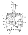
- FIG. 1 shows a manifold according to the invention
- FIG. 2 shows a partly cross section through the manifold in FIG. 1 ,
- FIG. 3 shows the manifold in an exploded view
- FIG. 4 shows a partly cross section through the manifold in exploded view in FIG. 3 ,
- FIG. 5 depicts a cross section of the fluid diverter element with the sealing means according to the invention
- FIG. 6 shows the fluid diverter element with the sealing means in an exploded view
- FIG. 7 shows a cross section of parts of the sealing means in FIG. 6 .
- FIG. 1 there is shown a manifold according to the invention, and in FIG. 2 a partly cross section of the manifold in FIG. 1 .
- the same elements are shown in exploded view in FIG. 3 and FIG. 4 .
- the manifold 1 comprises a housing 10 , which is mainly cylindrical in its outer form and has a centre axis 11 .
- the housing has in a cross section across the centre axis, preferably a polygonal outer form for easier connection of the piping (not shown) that that should be attached to the manifold.
- the housing comprises preferably a bottom 14 and walls 15 .
- the walls 15 forming the housing 10 comprise several fluid inlet apertures 12 and an outlet aperture 13 .
- These apertures 12 , 13 are all connected in the common void within the housing 10 , by this the inlets 12 are connected with the outlet 13 .
- All the inlet apertures 12 have centre axis which all are in a common plane mainly at right angle with the centre axis 11 of the housing 10 .
- the outlet aperture 13 has a centre axis parallel with the plane of the axis of the inlet apertures 12 .
- a fluid diverter system 20 comprising of a ring element 21 and a fluid diverter element 25 .
- the ring element 21 comprises a mainly cylindrical section with a bottom and a top flange 30 section.
- the top flange 30 forms a roof of the housing 10 when the manifold is assembled, as shown in FIG. 1 and FIG. 2 .
- the ring element 21 comprises apertures 22 A, 22 B corresponding to the apertures 12 , 13 in the housing 10 .
- the ring element 21 has an outer surface corresponding to an inner form of the housing 10 . This may in a cross section be cylindrical, polygonal or tapered in the longitudinal direction of the centre axis of the housing.
- the main feature is that fluid diverter system 20 easily may be inserted into the housing 10 , due to the corresponding inner surface of the housing and the outer surface of the ring element.
- the fluid diverter element 25 is arranged rotating about the centre axis 11 of the housing 10 , within the ring element 21 .
- the fluid diverter element 25 comprises an inlet 26 which may be positioned in alignment with one of the inlet apertures 12 in the housing 10 .
- the fluid diverter element 25 further comprises an outlet 27 which in the preferred embodiment is oriented in the longitudinal direction of the centre axis 11 of the housing 10 .
- the inlets may be arranged with an angle other than 90 degrees with the centre axis and the outlet with a different angle.
- the fluid diverter element further comprises a drive connection means 28 , which extends through the top flange 30 of the ring element 21 and which may be releasable connected to a drive element 5 , for instance in the form of an actuator.
- the drive connection means 28 may also be connected to operation means 6 , which may be manually operated or operated by a ROV or other equipments.
- the fluid diverter system 20 further comprises as best seen from FIGS. 3 and 4 lifting means 7 for lifting the fluid diverter system 20 in to and out of the housing 10 for assembling and disassembling of the manifold.
- the manifold also comprises guide means 8 , 8 ′, in the form of guide pins 8 arranged on the fluid diverter system and guides 8 ′ arranged on the housing 10 , for guiding the fluid diverter system 20 with its apertures in correct position in relation to the apertures in the housing 10 .
- the manifold also comprises locking means 9 for locking the fluid diverter system 20 to the housing 10 when the manifold is assembled.
- the dynamic sealing system 40 between the fluid diverter element 25 and the ring element 21 is shown in FIG. 5 to FIG. 7 .
- the inlet 26 of the fluid diverter element 25 has a sealing system 40 for sealing against the internal surface of the ring element 21 (not shown in FIG. 5-7 ).
- the fluid diverter element 25 also has a sealing element 50 around the outlet 27 .
- the sealing system 40 comprises a first element 41 .
- the first element 41 has a curved surface 42 in static abutment with the fluid diverter element 25 .
- the first element 41 may in a different embodiment be formed as part of the fluid diverter element 25 .
- the first element 41 comprises on the opposite side of the curved surface 42 an end surface comprising several grooves and step surfaces for interaction with other parts of the sealing system 40 .
- the sealing system 40 further comprises a spring element 44 , a seal booster 45 , a second element 46 and a sealing element 47 .
- the spring element 44 is arranged in between a step surface of the first element 41 and a surface of the second element 46 , giving some elasticity between the two elements 41 , 46 . As best seen from FIG.
- the seal booster 45 is arranged in a groove in the second element 46 and thereby in connection with the second element 46 on two sides.
- the seal booster 45 has a form and configuration which makes it seal both ways.
- the second element 46 has in a surface faced away from the fluid diverter element 25 a groove wherein the sealing element 47 is arranged.
- a surface 48 of the sealing element 47 face towards the inner surface of the ring element 21 has a corresponding configuration to the inner surface of the ring element around the apertures 22 , in the preferred embodiment spherical.
- the invention has now been explained with a preferred embodiment, there are however possible to make alterations and modifications to this embodiments which are within the scope of the invention as defined in the following claims. It is thinkable to have a housing comprising bottom and walls, and a separate roof which is positioned in abutment against the walls when the fluid diverter system is inserted into the housing.
- the ring element may not comprise a bottom.
Landscapes
- Engineering & Computer Science (AREA)
- General Engineering & Computer Science (AREA)
- Mechanical Engineering (AREA)
- Quick-Acting Or Multi-Walled Pipe Joints (AREA)
- Spinning Methods And Devices For Manufacturing Artificial Fibers (AREA)
- Valve-Gear Or Valve Arrangements (AREA)
- Multiple-Way Valves (AREA)
- Fluid-Driven Valves (AREA)
Applications Claiming Priority (3)
| Application Number | Priority Date | Filing Date | Title |
|---|---|---|---|
| NO20051611A NO322524B1 (no) | 2005-03-31 | 2005-03-31 | Manifold |
| NO20051611 | 2005-03-31 | ||
| PCT/NO2006/000120 WO2006104393A1 (en) | 2005-03-31 | 2006-03-31 | Manifold |
Publications (2)
| Publication Number | Publication Date |
|---|---|
| US20090266424A1 US20090266424A1 (en) | 2009-10-29 |
| US8899269B2 true US8899269B2 (en) | 2014-12-02 |
Family
ID=35266173
Family Applications (1)
| Application Number | Title | Priority Date | Filing Date |
|---|---|---|---|
| US11/887,605 Active 2029-12-09 US8899269B2 (en) | 2005-03-31 | 2006-03-31 | Manifold |
Country Status (8)
| Country | Link |
|---|---|
| US (1) | US8899269B2 (de) |
| EP (1) | EP1864043B1 (de) |
| CN (1) | CN101189463B (de) |
| AT (1) | ATE440238T1 (de) |
| BR (1) | BRPI0609533A2 (de) |
| DE (1) | DE602006008589D1 (de) |
| NO (1) | NO322524B1 (de) |
| WO (1) | WO2006104393A1 (de) |
Cited By (7)
| Publication number | Priority date | Publication date | Assignee | Title |
|---|---|---|---|---|
| US9228664B2 (en) * | 2014-06-05 | 2016-01-05 | Charles C. Partridge | Rotary multi-port valve |
| RU2657383C1 (ru) * | 2017-09-01 | 2018-06-13 | Акционерное общество "ГМС Нефтемаш" | Переключатель скважин многоходовой |
| RU183413U1 (ru) * | 2017-11-27 | 2018-09-21 | Общество с ограниченной ответственностью Научно-производственная компания "Калибр" | Переключатель скважин многоходовой |
| US10094480B2 (en) * | 2017-01-24 | 2018-10-09 | Charles C. Partridge | Rotary multi-port valve |
| US20220003327A1 (en) * | 2018-05-18 | 2022-01-06 | Mogas Industries, Inc. | Multiport Valve |
| RU2769624C1 (ru) * | 2021-08-23 | 2022-04-04 | Публичное акционерное общество «Татнефть» имени В.Д. Шашина | Переключатель потока жидкости |
| RU2780390C1 (ru) * | 2021-12-03 | 2022-09-22 | Акционерное Общество "Озна-Измерительные Системы" | Устройство сочленения уплотнения клапана и корпуса переключателя скважин многоходового |
Families Citing this family (4)
| Publication number | Priority date | Publication date | Assignee | Title |
|---|---|---|---|---|
| NO329101B1 (no) | 2008-05-20 | 2010-08-23 | Framo Eng As | Arrangement for styring av en fluidstrom |
| WO2019204519A1 (en) * | 2018-04-17 | 2019-10-24 | Fmc Technologies, Inc. | Frac transfer diverter valve |
| JP2023038775A (ja) * | 2021-09-07 | 2023-03-17 | 株式会社不二工機 | 弁装置及び弁本体部 |
| CN114001231A (zh) * | 2021-10-28 | 2022-02-01 | 浙江银轮机械股份有限公司 | 一种歧管结构 |
Citations (20)
| Publication number | Priority date | Publication date | Assignee | Title |
|---|---|---|---|---|
| US2492140A (en) | 1944-01-22 | 1949-12-27 | Thompson Prod Inc | Fluid flow control device |
| US2821998A (en) * | 1956-01-27 | 1958-02-04 | Win Well Mfg Company | Rotary selector valve |
| US3799191A (en) * | 1972-01-31 | 1974-03-26 | Exxon Production Research Co | Compartmented underwater equipment |
| US4262688A (en) * | 1979-05-25 | 1981-04-21 | Acf Industries, Incorporated | Metal seat assemblies for valves |
| JPS57103977A (en) | 1980-07-28 | 1982-06-28 | Yoneda Kogyo Kk | Five-way change-over valve |
| US4437521A (en) * | 1982-04-26 | 1984-03-20 | Mobil Oil Corporation | Subsea wellhead connection assembly and methods of installation |
| US4444218A (en) * | 1980-10-30 | 1984-04-24 | Koomey, Inc. | Underwater fluid connector |
| US4562860A (en) * | 1983-07-06 | 1986-01-07 | Wilmington Trust Company | Ball valve having easy maintenance features for extreme environments |
| US4606368A (en) * | 1983-07-22 | 1986-08-19 | Forsac Valves Limited | Ball valve for pipeline |
| EP0198129A2 (de) | 1985-04-16 | 1986-10-22 | AGIP PETROLI S.p.A. | Absperr- und Mehrweghahn mit Kugelküken und Ventilanordnung mit demselben |
| US4911413A (en) * | 1989-05-23 | 1990-03-27 | Kitamura Valve Mfg. Co., Ltd. | Structure for fitting a valve seat support ring in a valve port |
| US4968334A (en) | 1989-09-08 | 1990-11-06 | Hilton Thomas J | Remotely-controlled multi-port valve having a multi-vane rotating central drum element |
| US5035258A (en) * | 1989-11-08 | 1991-07-30 | Cooper Industries, Inc. | Valve with removable insert |
| WO1997005413A1 (en) | 1995-07-28 | 1997-02-13 | Siegmund Nafz | Device for distributing fluids |
| AT404172B (de) | 1995-10-06 | 1998-09-25 | Praher Ludwig | Mehrwegeventil |
| US6082707A (en) * | 1998-10-23 | 2000-07-04 | Gulf Technologies International, L.C. | Valve seat and method |
| US6161618A (en) * | 1998-08-06 | 2000-12-19 | Dtc International, Inc. | Subsea control module |
| US6196266B1 (en) * | 1998-01-16 | 2001-03-06 | Silvano Breda | Multiport diverter valve |
| US6345645B1 (en) | 1999-12-01 | 2002-02-12 | Caretaker Systems, Inc. | Fluid distribution valve |
| US7343932B2 (en) * | 2004-04-27 | 2008-03-18 | Cameron International Corporation | Multiple line administration |
Family Cites Families (2)
| Publication number | Priority date | Publication date | Assignee | Title |
|---|---|---|---|---|
| NO310942B1 (no) | 1995-07-28 | 2001-09-17 | Siegmund Nafz | Anordning for fordeling av fluider og anvendelse av anordningen |
| WO1999045302A1 (en) * | 1998-03-05 | 1999-09-10 | The Swagelok Company | Modular surface mount manifold |
-
2005
- 2005-03-31 NO NO20051611A patent/NO322524B1/no not_active IP Right Cessation
-
2006
- 2006-03-31 DE DE200660008589 patent/DE602006008589D1/de active Active
- 2006-03-31 CN CN2006800192310A patent/CN101189463B/zh not_active Expired - Fee Related
- 2006-03-31 EP EP06733099A patent/EP1864043B1/de active Active
- 2006-03-31 BR BRPI0609533-0A patent/BRPI0609533A2/pt not_active IP Right Cessation
- 2006-03-31 AT AT06733099T patent/ATE440238T1/de not_active IP Right Cessation
- 2006-03-31 US US11/887,605 patent/US8899269B2/en active Active
- 2006-03-31 WO PCT/NO2006/000120 patent/WO2006104393A1/en active Application Filing
Patent Citations (20)
| Publication number | Priority date | Publication date | Assignee | Title |
|---|---|---|---|---|
| US2492140A (en) | 1944-01-22 | 1949-12-27 | Thompson Prod Inc | Fluid flow control device |
| US2821998A (en) * | 1956-01-27 | 1958-02-04 | Win Well Mfg Company | Rotary selector valve |
| US3799191A (en) * | 1972-01-31 | 1974-03-26 | Exxon Production Research Co | Compartmented underwater equipment |
| US4262688A (en) * | 1979-05-25 | 1981-04-21 | Acf Industries, Incorporated | Metal seat assemblies for valves |
| JPS57103977A (en) | 1980-07-28 | 1982-06-28 | Yoneda Kogyo Kk | Five-way change-over valve |
| US4444218A (en) * | 1980-10-30 | 1984-04-24 | Koomey, Inc. | Underwater fluid connector |
| US4437521A (en) * | 1982-04-26 | 1984-03-20 | Mobil Oil Corporation | Subsea wellhead connection assembly and methods of installation |
| US4562860A (en) * | 1983-07-06 | 1986-01-07 | Wilmington Trust Company | Ball valve having easy maintenance features for extreme environments |
| US4606368A (en) * | 1983-07-22 | 1986-08-19 | Forsac Valves Limited | Ball valve for pipeline |
| EP0198129A2 (de) | 1985-04-16 | 1986-10-22 | AGIP PETROLI S.p.A. | Absperr- und Mehrweghahn mit Kugelküken und Ventilanordnung mit demselben |
| US4911413A (en) * | 1989-05-23 | 1990-03-27 | Kitamura Valve Mfg. Co., Ltd. | Structure for fitting a valve seat support ring in a valve port |
| US4968334A (en) | 1989-09-08 | 1990-11-06 | Hilton Thomas J | Remotely-controlled multi-port valve having a multi-vane rotating central drum element |
| US5035258A (en) * | 1989-11-08 | 1991-07-30 | Cooper Industries, Inc. | Valve with removable insert |
| WO1997005413A1 (en) | 1995-07-28 | 1997-02-13 | Siegmund Nafz | Device for distributing fluids |
| AT404172B (de) | 1995-10-06 | 1998-09-25 | Praher Ludwig | Mehrwegeventil |
| US6196266B1 (en) * | 1998-01-16 | 2001-03-06 | Silvano Breda | Multiport diverter valve |
| US6161618A (en) * | 1998-08-06 | 2000-12-19 | Dtc International, Inc. | Subsea control module |
| US6082707A (en) * | 1998-10-23 | 2000-07-04 | Gulf Technologies International, L.C. | Valve seat and method |
| US6345645B1 (en) | 1999-12-01 | 2002-02-12 | Caretaker Systems, Inc. | Fluid distribution valve |
| US7343932B2 (en) * | 2004-04-27 | 2008-03-18 | Cameron International Corporation | Multiple line administration |
Cited By (8)
| Publication number | Priority date | Publication date | Assignee | Title |
|---|---|---|---|---|
| US9228664B2 (en) * | 2014-06-05 | 2016-01-05 | Charles C. Partridge | Rotary multi-port valve |
| US10094480B2 (en) * | 2017-01-24 | 2018-10-09 | Charles C. Partridge | Rotary multi-port valve |
| RU2657383C1 (ru) * | 2017-09-01 | 2018-06-13 | Акционерное общество "ГМС Нефтемаш" | Переключатель скважин многоходовой |
| RU183413U1 (ru) * | 2017-11-27 | 2018-09-21 | Общество с ограниченной ответственностью Научно-производственная компания "Калибр" | Переключатель скважин многоходовой |
| US20220003327A1 (en) * | 2018-05-18 | 2022-01-06 | Mogas Industries, Inc. | Multiport Valve |
| US11796074B2 (en) * | 2018-05-18 | 2023-10-24 | Mogas Industries, Inc. | Multiport valve |
| RU2769624C1 (ru) * | 2021-08-23 | 2022-04-04 | Публичное акционерное общество «Татнефть» имени В.Д. Шашина | Переключатель потока жидкости |
| RU2780390C1 (ru) * | 2021-12-03 | 2022-09-22 | Акционерное Общество "Озна-Измерительные Системы" | Устройство сочленения уплотнения клапана и корпуса переключателя скважин многоходового |
Also Published As
| Publication number | Publication date |
|---|---|
| ATE440238T1 (de) | 2009-09-15 |
| EP1864043A1 (de) | 2007-12-12 |
| EP1864043B1 (de) | 2009-08-19 |
| BRPI0609533A2 (pt) | 2010-04-13 |
| DE602006008589D1 (de) | 2009-10-01 |
| WO2006104393A1 (en) | 2006-10-05 |
| US20090266424A1 (en) | 2009-10-29 |
| CN101189463A (zh) | 2008-05-28 |
| CN101189463B (zh) | 2011-09-07 |
| NO20051611D0 (no) | 2005-03-31 |
| NO322524B1 (no) | 2006-10-16 |
Similar Documents
| Publication | Publication Date | Title |
|---|---|---|
| US8899269B2 (en) | Manifold | |
| US9915275B2 (en) | Stacked shuttle valve | |
| JP7101209B2 (ja) | 容易に交換可能な部品を有する濃厚相ポンプ | |
| JP4740997B2 (ja) | 拡張可能な気体又は液体分配システム | |
| EP3695155B1 (de) | Drehverbindung mit mehreren durchgängen | |
| JP4921457B2 (ja) | 拡張可能な気体又は液体分配システム | |
| US7357145B2 (en) | High-pressure, hemi-wedge cartridge valve | |
| US20100219185A1 (en) | Sealing System For Pressure Vessels | |
| CN101142433A (zh) | 用于流体的歧管 | |
| JP2008537988A (ja) | 拡張可能な気体又は液体分配システム | |
| US10145478B2 (en) | Top entry soft seats floating ball valve | |
| AU2006229553B2 (en) | Manifold | |
| US8413672B2 (en) | Valve flushing kit | |
| KR20140116082A (ko) | 신속 유지보수 해저 체크 밸브 | |
| EP3803091A1 (de) | Gasversorgungssystem | |
| US20080223447A1 (en) | Serviceable double block and bleed valve | |
| CN217153103U (zh) | 分歧阀结构 | |
| CN212775724U (zh) | 分歧阀结构 | |
| GB2516966A (en) | Pipeline connector and joint |
Legal Events
| Date | Code | Title | Description |
|---|---|---|---|
| AS | Assignment |
Owner name: FRAMO ENGINEERING AS, NORWAY Free format text: ASSIGNMENT OF ASSIGNORS INTEREST;ASSIGNOR:SEIM, LARS;REEL/FRAME:022895/0131 Effective date: 20080109 |
|
| STCF | Information on status: patent grant |
Free format text: PATENTED CASE |
|
| FEPP | Fee payment procedure |
Free format text: PAYOR NUMBER ASSIGNED (ORIGINAL EVENT CODE: ASPN); ENTITY STATUS OF PATENT OWNER: LARGE ENTITY |
|
| MAFP | Maintenance fee payment |
Free format text: PAYMENT OF MAINTENANCE FEE, 4TH YEAR, LARGE ENTITY (ORIGINAL EVENT CODE: M1551) Year of fee payment: 4 |
|
| MAFP | Maintenance fee payment |
Free format text: PAYMENT OF MAINTENANCE FEE, 8TH YEAR, LARGE ENTITY (ORIGINAL EVENT CODE: M1552); ENTITY STATUS OF PATENT OWNER: LARGE ENTITY Year of fee payment: 8 |