US8852440B2 - Filter unit and method for operating the filter unit - Google Patents
Filter unit and method for operating the filter unit Download PDFInfo
- Publication number
- US8852440B2 US8852440B2 US13/984,585 US201213984585A US8852440B2 US 8852440 B2 US8852440 B2 US 8852440B2 US 201213984585 A US201213984585 A US 201213984585A US 8852440 B2 US8852440 B2 US 8852440B2
- Authority
- US
- United States
- Prior art keywords
- filter
- cartridge
- main
- auxiliary
- alarm
- Prior art date
- Legal status (The legal status is an assumption and is not a legal conclusion. Google has not performed a legal analysis and makes no representation as to the accuracy of the status listed.)
- Active
Links
- 238000000034 method Methods 0.000 title claims description 4
- 238000001914 filtration Methods 0.000 claims abstract description 40
- 238000011144 upstream manufacturing Methods 0.000 claims 1
- 239000010687 lubricating oil Substances 0.000 description 15
- 230000001960 triggered effect Effects 0.000 description 6
- 230000005540 biological transmission Effects 0.000 description 5
- 238000010586 diagram Methods 0.000 description 4
- 238000011109 contamination Methods 0.000 description 3
- 239000003921 oil Substances 0.000 description 3
- 230000008901 benefit Effects 0.000 description 2
- 238000010276 construction Methods 0.000 description 2
- 239000012535 impurity Substances 0.000 description 2
- 230000033228 biological regulation Effects 0.000 description 1
- 238000009434 installation Methods 0.000 description 1
- 239000002245 particle Substances 0.000 description 1
- 230000001681 protective effect Effects 0.000 description 1
- 230000000717 retained effect Effects 0.000 description 1
Images


Classifications
-
- B—PERFORMING OPERATIONS; TRANSPORTING
- B01—PHYSICAL OR CHEMICAL PROCESSES OR APPARATUS IN GENERAL
- B01D—SEPARATION
- B01D35/00—Filtering devices having features not specifically covered by groups B01D24/00 - B01D33/00, or for applications not specifically covered by groups B01D24/00 - B01D33/00; Auxiliary devices for filtration; Filter housing constructions
- B01D35/12—Devices for taking out of action one or more units of multi- unit filters, e.g. for regeneration
Definitions
- the invention relates to a filter unit and to a method for operating the filter unit.
- Filter units having two filter cartridges, are known as so-called duplex filters and are used particularly as lubricating oil filters for marine transmissions.
- duplex filters are used particularly as lubricating oil filters for marine transmissions.
- a switching device is provided by means of which one filter is switched off and the other filter has a flow passing through it.
- the shut off filter can be exchanged. Due to the two identical filter cartridges, such duplex filters are relatively large, heavy and expensive.
- gap-type filters are also known that do not need to be exchanged because they can be cleaned during operation.
- a disadvantage with the gap-type filters is that a maximum grade of filtration cannot be attained.
- the gap-type filter has a grade of filtration limit of approximately 50 ⁇ m. The grade of filtration is determined by the gap width; there is no filtering in the depth, rather filtration occurs only in a filter plane.
- the GB 1,164,628 document discloses a duplex filter for a marine transmission, thus a lubricating oil filter.
- Such known duplex filters have two identical filter cartridges, which can be populated with different filter elements, for example, with a paper filter element or fine filter element, or a coarse filter element in the form of a sieve filter.
- the fine filter is provided for the time period during which the marine machine is being broken-in. After this initial break-in phase, the fine filter is replaced by the coarse filter, a fine filter is no longer used after the initial break-in phase.
- the exchange from the fine filter to the coarse filter occurs by actuating a switching device, which allows the exchange of the fine filter cartridge while the machine is running.
- the problem addressed by the present invention is to provide a filter unit of the initially named type, which allows a filter exchange with the machine running, however, is designed having less volume, and a smaller construction space is required for the installation.
- a main cartridge and an auxiliary cartridge are provided, wherein the auxiliary cartridge is substantially smaller with respect to its outer dimensions than the main cartridge.
- a fine filter element provided in the main cartridge is intended for the continuous operation.
- a coarse filter is provided in the auxiliary cartridge that is required only for the time during which the main cartridge is exchanged.
- the lubricating oil is only cleaned via a coarse filter.
- a relative impurity of the lubricating oil with the smallest particles which cannot be retained by the coarse filter, can be acceptable because after the filter is exchanged, the lubricating oil is again cleaned using the fine filter. Due to the smaller auxiliary cartridge, the filter unit, according to the invention, requires less construction space and weight, and saves costs.
- the auxiliary cartridge is disposed above the main cartridge. This results in a relatively compact design for the filter unit which only minimally exceeds the diameter of the main cartridge.
- the inflow and the return flow of the auxiliary cartridge are disposed coaxially with the inlet and outlet of the filter unit. This results in a short and low-loss inflow and outflow for the auxiliary cartridge.
- the fine filter has a grade of filtration of approximately 10 ⁇ m—which corresponds to the generally required specifications for the filtering of lubricating oil of marine transmissions.
- the coarse filter has a grade of filtration of approximately 40 ⁇ m.
- the coarse filter is approximately four times coarser than the fine filter, and thus permits a corresponding smaller auxiliary cartridge, in comparison to the size of the main cartridge.
- Such a grade of filtration is sufficient to keep the lubricating oil free of coarse impurities during a duration of a few minutes.
- the pressure loss in the auxiliary cartridge is set to the same threshold value as the pressure loss in the main cartridge in the case of a contaminated fine filter, at which the differential pressure switch is activated and an alarm is triggered. This has the consequence that while the main filter is being changed, a continuous alarm sounds which is shut off only after switching back to fine filter operation.
- the differential pressure switch is switched such that the continuous alarm is triggered during actuation of the switching device, that is, when the switch lever is actuated.
- This alternative has the advantage of attaining greater reliability during filter changes because the alarm is triggered independently of the pressure decrease at the auxiliary filter.
- the switching device is actuated, the oil supply to the main filter is interrupted and the oil to be filtered is supplied to the auxiliary cartridge having the coarse filter.
- the fine filtering is interrupted for a short time, that is, for the filter change, and is replaced by coarse filtering. This coarse filtering is sufficient in order to protect the transmission from damage.
- a continuous alarm is triggered during exchange of the main cartridge. This prevents the danger of forgetting to switch back to the fine filter operation after the filter change.
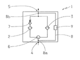
- FIG. 1 a circuit diagram for the arrangement of the main and the auxiliary filter
- FIG. 2 a filter unit during operation of the main filter
- FIG. 3 the filter unit during operation of the auxiliary filter
- FIG. 4 a circuit arrangement for the differential pressure switch.
- FIG. 1 shows a circuit diagram 1 having the arrangement of a main filter 2 and, in parallel, an auxiliary filter 3 , also called protective filter 3 .
- the circuit diagram 1 further shows an inlet 4 , for a flow medium to be filtered, and an outlet 5 .
- a switching device 6 which steers the flow medium through either the main filter 2 or the auxiliary filter 3 , is disposed along the flow direction after the inlet 4 .
- a non-return valve 7 which is open in the direction of the outlet 5 and is closed in direction of main filter 2 , is disposed in the flow direction after the main filter 2 .
- a measuring section 8 located between the inlet 4 and the outlet 5 , having a first pressure sensor 8 a and a second pressure sensor 8 b for measuring the differential pressure between the inlet 4 and outlet 5 , that is, either a pressure loss in the main filter 2 or in the auxiliary filter 3 is measured and supplied to a differential pressure switch 9 .
- the differential pressure switch 9 can be coupled to an alarm device.
- FIG. 2 shows a filter unit 10 , implemented as a lubricating oil filter, having a filter housing 11 which has an inlet connection 12 and an outlet connection 13 , also simply called inlet 12 and outlet 13 .
- a main filter implemented as a main cartridge 14
- a fine filter not shown here, which filters the lubricating oil entering through the inlet connection 12
- An auxiliary cartridge 15 which contains a coarse filter, not shown, is disposed above the main cartridge 14 .
- the auxiliary cartridge 15 is substantially smaller and lighter than the main cartridge 14 ; in a preferred example embodiment, it has less than 40% of the volume of the main cartridge.
- the filter unit 10 further has a switching lever 16 , which is part of a switching device, not shown in more detail.
- the filter unit 10 also has a differential pressure switch 17 which reacts to the pressure loss between the inlet 12 and the outlet 13 , or the pressure loss in the main cartridge 14 or in the auxiliary cartridge 15 .
- the shown filter unit 10 is preferably used as a lubricating oil filter for marine transmissions.
- FIG. 2 shows the regular operation with the main filter 14 , that is, fine filtering of the lubricating oil.
- the flow of the lubricating oil is represented by arrow F.
- the fine filter has a preferred grade of filtration of approx. 10 ⁇ m.
- the switching device 16 is set so that the entering lubricating oil flows through the main filter 14 while, at the same time, the auxiliary filter, or the auxiliary cartridge 15 , is blocked for through flow.
- the lubricating oil is fine filtered.
- the pressure loss is continuously measured and further transmitted to the differential pressure switch 17 which, upon reaching a predetermined threshold value, reacts and triggers an alarm. As a rule, the threshold value is attained when the fine filter in the main cartridge 14 is contaminated.
- FIG. 3 shows the filter unit 10 after actuation of the switching device 16 , and particularly in the manner that the main cartridge 14 is blocked, for a through flow, and is bypassed.
- the lubricating oil flows through the auxiliary cartridge 15 , according to the flow arrows G, which has an inlet opening 18 and an outlet opening 19 , which are disposed approximately coaxial to or aligned with the inlet connection 12 and the outlet connection 13 of the filter unit 10 .
- the oil flow circulates above the main cartridge 14 , with respect to the longitudinal axis a thereof.
- the coarse filter disposed in the auxiliary cartridge 15 , has a grade of filtration of approx. 40 ⁇ m, thus approximately four times coarser than the fine filter in the main cartridge 14 .
- the pressure drop in the main cartridge 15 is set so that the threshold value, which triggers the alarm, is always exceeded during coarse filtering. In this respect, there is a continuous alarm while changing the main cartridge 14 .
- the switching of the switching device 16 is not forgotten, that is, moving the switching lever 16 such that fine filtering occurs again according to FIG. 2 .
- the filter changes takes approximately 3-5 minutes so that the time duration, of coarse filtering, is relatively short, and thus, noncritical.
- FIG. 4 shows a further circuit arrangement 20 for a main filter 21 , an auxiliary filter 22 , a differential pressure switch 23 , a switching device 24 , and a non-return valve 25 .
- An inlet line, for the flow medium, is indicated with 26 and an outlet line is indicated with 27 .
- the main filter 21 and the auxiliary filter 22 are connected, in parallel, between the inlet line 26 and the outlet line 27 , wherein the switching device 24 steers the flow medium either via the main filter 21 or via the auxiliary filter 22 .
- the switching device 24 is set so that the flow medium flows through the main filter 21 .
- the differential pressure switch 23 measures the pressure loss of the main filter 21 and upon attaining a threshold value, which corresponds to a defined degree of contamination of the main filter 21 , triggers an alarm.
- the switching device 24 is switched, preferably using a switch lever 16 , represented in FIG. 3 , so that the flow medium flows through the auxiliary filter 22 , implemented as a coarse filter. Thus, the main filter 21 is blocked.
- the differential pressure switch 23 now measures only the pressure present at the pressure sensor 28 , in the inlet line 26 , which is higher than the pressure loss at the main filter 21 occurring in the case of contamination, such that a continuous alarm is triggered. Only when the filter changes is completed and the switching device 24 is again switched back to normal operation, is the alarm shut off. Using this circuit variant, it is guaranteed that a continuous alarm is always triggered with movement of the switch lever of the switching device 24 , and particularly, independently of the pressure decrease in the auxiliary filter 22 .
Landscapes
- Chemical & Material Sciences (AREA)
- Chemical Kinetics & Catalysis (AREA)
- Filtration Of Liquid (AREA)
- Filtering Of Dispersed Particles In Gases (AREA)
Applications Claiming Priority (4)
| Application Number | Priority Date | Filing Date | Title |
|---|---|---|---|
| DE102011004367A DE102011004367A1 (de) | 2011-02-18 | 2011-02-18 | Filtereinheit und Verfahren zum Betreiben der Filtereinheit |
| DE102011004367 | 2011-02-18 | ||
| DE102011004367.5 | 2011-02-18 | ||
| PCT/EP2012/050067 WO2012110260A1 (de) | 2011-02-18 | 2012-01-04 | Filtereinheit und verfahren zum betreiben der filtereinheit |
Publications (2)
| Publication Number | Publication Date |
|---|---|
| US20130313203A1 US20130313203A1 (en) | 2013-11-28 |
| US8852440B2 true US8852440B2 (en) | 2014-10-07 |
Family
ID=45529066
Family Applications (1)
| Application Number | Title | Priority Date | Filing Date |
|---|---|---|---|
| US13/984,585 Active US8852440B2 (en) | 2011-02-18 | 2012-01-04 | Filter unit and method for operating the filter unit |
Country Status (5)
| Country | Link |
|---|---|
| US (1) | US8852440B2 (de) |
| EP (1) | EP2675544B1 (de) |
| CN (1) | CN103384555B (de) |
| DE (1) | DE102011004367A1 (de) |
| WO (1) | WO2012110260A1 (de) |
Families Citing this family (4)
| Publication number | Priority date | Publication date | Assignee | Title |
|---|---|---|---|---|
| DE102012010895A1 (de) * | 2012-06-01 | 2013-12-05 | Hydac Filtertechnik Gmbh | Filtervorrichtung für Fluide |
| CN105999827A (zh) * | 2016-07-06 | 2016-10-12 | 辽宁科技学院 | 一种可以连续工作的过滤装置及压力系统 |
| CN106039821A (zh) * | 2016-07-20 | 2016-10-26 | 江苏海阳锦纶新材料有限公司 | 一种单体回收浓缩液过滤装置 |
| CN110604957A (zh) * | 2019-08-28 | 2019-12-24 | 北京欧洛普过滤技术开发公司 | 一种智能过滤器装置 |
Citations (9)
| Publication number | Priority date | Publication date | Assignee | Title |
|---|---|---|---|---|
| GB258905A (en) | 1925-09-26 | 1927-01-13 | Jean Zwicky | Improvements in filters |
| GB1023178A (en) | 1963-07-26 | 1966-03-23 | Winslow Engineering And Mfg Co | Improvements relating to filters |
| GB1164628A (en) | 1966-11-04 | 1969-09-17 | Blacklstone & Company Ltd | Improvements in or relating to the Filtration of Fluids |
| DE8805945U1 (de) | 1988-05-04 | 1988-07-28 | Amtec Kistler Gmbh, 8905 Mering, De | |
| DE4424810A1 (de) | 1994-07-14 | 1996-01-18 | Knecht Filterwerke Gmbh | Filtervorrichtung |
| US6888466B2 (en) * | 2003-04-10 | 2005-05-03 | John Dermody | Air filter timer |
| US20060162302A1 (en) * | 2005-01-21 | 2006-07-27 | Black & Decker Inc. | Filter for pneumatic tool |
| US7279091B2 (en) * | 2001-02-08 | 2007-10-09 | Hydac Filtertechnik Gmbh. | Filter device |
| US7618480B2 (en) * | 2007-07-16 | 2009-11-17 | Flair Corporation | Filter assembly and method |
Family Cites Families (1)
| Publication number | Priority date | Publication date | Assignee | Title |
|---|---|---|---|---|
| CN201454247U (zh) * | 2009-02-07 | 2010-05-12 | 杜也兵 | 带反冲装置净水器 |
-
2011
- 2011-02-18 DE DE102011004367A patent/DE102011004367A1/de not_active Withdrawn
-
2012
- 2012-01-04 US US13/984,585 patent/US8852440B2/en active Active
- 2012-01-04 WO PCT/EP2012/050067 patent/WO2012110260A1/de active Application Filing
- 2012-01-04 CN CN201280009533.5A patent/CN103384555B/zh active Active
- 2012-01-04 EP EP12700935.5A patent/EP2675544B1/de active Active
Patent Citations (10)
| Publication number | Priority date | Publication date | Assignee | Title |
|---|---|---|---|---|
| GB258905A (en) | 1925-09-26 | 1927-01-13 | Jean Zwicky | Improvements in filters |
| GB1023178A (en) | 1963-07-26 | 1966-03-23 | Winslow Engineering And Mfg Co | Improvements relating to filters |
| DE1977428U (de) | 1963-07-26 | 1968-01-25 | Winslow Engineering And Mfg Co | Filteraggregat. |
| GB1164628A (en) | 1966-11-04 | 1969-09-17 | Blacklstone & Company Ltd | Improvements in or relating to the Filtration of Fluids |
| DE8805945U1 (de) | 1988-05-04 | 1988-07-28 | Amtec Kistler Gmbh, 8905 Mering, De | |
| DE4424810A1 (de) | 1994-07-14 | 1996-01-18 | Knecht Filterwerke Gmbh | Filtervorrichtung |
| US7279091B2 (en) * | 2001-02-08 | 2007-10-09 | Hydac Filtertechnik Gmbh. | Filter device |
| US6888466B2 (en) * | 2003-04-10 | 2005-05-03 | John Dermody | Air filter timer |
| US20060162302A1 (en) * | 2005-01-21 | 2006-07-27 | Black & Decker Inc. | Filter for pneumatic tool |
| US7618480B2 (en) * | 2007-07-16 | 2009-11-17 | Flair Corporation | Filter assembly and method |
Non-Patent Citations (3)
| Title |
|---|
| German Search Report for corresponding application de 10 2011 004 367.5 mailed on Jul. 14, 2011. |
| International Search Report for corresponding application PCT/EP2012/050067 mailed on Mar. 27, 2012. |
| Written Opinion for corresponding application PCT/EP2012/050067 mailed on Mar. 27, 2012. |
Also Published As
| Publication number | Publication date |
|---|---|
| DE102011004367A1 (de) | 2012-08-23 |
| EP2675544A1 (de) | 2013-12-25 |
| EP2675544B1 (de) | 2016-10-05 |
| CN103384555B (zh) | 2015-04-15 |
| WO2012110260A1 (de) | 2012-08-23 |
| US20130313203A1 (en) | 2013-11-28 |
| CN103384555A (zh) | 2013-11-06 |
Similar Documents
| Publication | Publication Date | Title |
|---|---|---|
| EP0534672B1 (de) | Filtereinheit | |
| US3270884A (en) | Dual valve, dual element fluid filter assembly | |
| US8852440B2 (en) | Filter unit and method for operating the filter unit | |
| US3331509A (en) | Strainer | |
| JP6832855B2 (ja) | 特に船用エンジンのような船舶ユニットのための潤滑油を濾過する濾過システム | |
| EP0500487B1 (de) | Verbessertes Schmierölfilterverfahren und Vorrichtung | |
| US9339746B2 (en) | Method for filtering a liquid | |
| CN102753244B (zh) | 过滤装置和使用在该过滤装置中的过滤元件 | |
| US5653880A (en) | Device for separating and filtering particles in a flow of fluid | |
| US20040074827A1 (en) | Filter device | |
| CN105275690B (zh) | 燃料过滤器异常检测装置 | |
| US3262564A (en) | Dual valve, dual filter element, constant flow filter assembly | |
| CN108348826B (zh) | 用于集成压差传感器的系统和方法 | |
| EP2336505A2 (de) | Filtersystem zur Lieferung von Schmiermittel | |
| US6818122B2 (en) | Dual stage filter element bypass valve | |
| US3053389A (en) | Oil filters | |
| US9480937B2 (en) | Hydraulic filter | |
| KR20130005685A (ko) | 오일필터 바이패스밸브 | |
| JP6572666B2 (ja) | オイルフィルタ及び内燃機関 | |
| US20170312659A1 (en) | Filter arrangement having burst disc arrangement | |
| US6911062B1 (en) | Filter assembly utilizing dual filter elements and a pressure responsive member to provide differential pressure actuated switchover | |
| CN102954067A (zh) | 双筒过滤器 | |
| JP5951902B1 (ja) | 燃料システム | |
| CN103821797A (zh) | 一种过滤过程中可相互切换的双筒过滤器 | |
| KR20140075620A (ko) | 밸브 유닛, 유압 시스템, 차량 |
Legal Events
| Date | Code | Title | Description |
|---|---|---|---|
| AS | Assignment |
Owner name: ZF FRIEDRICHSHAFEN AG, GERMANY Free format text: ASSIGNMENT OF ASSIGNORS INTEREST;ASSIGNOR:SAGAWE, JOACHIM;REEL/FRAME:031009/0094 Effective date: 20130705 |
|
| FEPP | Fee payment procedure |
Free format text: PAYOR NUMBER ASSIGNED (ORIGINAL EVENT CODE: ASPN); ENTITY STATUS OF PATENT OWNER: LARGE ENTITY |
|
| STCF | Information on status: patent grant |
Free format text: PATENTED CASE |
|
| MAFP | Maintenance fee payment |
Free format text: PAYMENT OF MAINTENANCE FEE, 4TH YEAR, LARGE ENTITY (ORIGINAL EVENT CODE: M1551) Year of fee payment: 4 |
|
| MAFP | Maintenance fee payment |
Free format text: PAYMENT OF MAINTENANCE FEE, 8TH YEAR, LARGE ENTITY (ORIGINAL EVENT CODE: M1552); ENTITY STATUS OF PATENT OWNER: LARGE ENTITY Year of fee payment: 8 |