US8821378B2 - Device and method for minimally invasive spinal intervention - Google Patents
Device and method for minimally invasive spinal intervention Download PDFInfo
- Publication number
- US8821378B2 US8821378B2 US12/516,316 US51631607A US8821378B2 US 8821378 B2 US8821378 B2 US 8821378B2 US 51631607 A US51631607 A US 51631607A US 8821378 B2 US8821378 B2 US 8821378B2
- Authority
- US
- United States
- Prior art keywords
- cutting edge
- tool
- cutting tool
- distal end
- cutting
- Prior art date
- Legal status (The legal status is an assumption and is not a legal conclusion. Google has not performed a legal analysis and makes no representation as to the accuracy of the status listed.)
- Active, expires
Links
Images


Classifications
-
- A—HUMAN NECESSITIES
- A61—MEDICAL OR VETERINARY SCIENCE; HYGIENE
- A61B—DIAGNOSIS; SURGERY; IDENTIFICATION
- A61B17/00—Surgical instruments, devices or methods, e.g. tourniquets
- A61B17/16—Bone cutting, breaking or removal means other than saws, e.g. Osteoclasts; Drills or chisels for bones; Trepans
- A61B17/1659—Surgical rasps, files, planes, or scrapers
-
- A—HUMAN NECESSITIES
- A61—MEDICAL OR VETERINARY SCIENCE; HYGIENE
- A61B—DIAGNOSIS; SURGERY; IDENTIFICATION
- A61B1/00—Instruments for performing medical examinations of the interior of cavities or tubes of the body by visual or photographical inspection, e.g. endoscopes; Illuminating arrangements therefor
- A61B1/313—Instruments for performing medical examinations of the interior of cavities or tubes of the body by visual or photographical inspection, e.g. endoscopes; Illuminating arrangements therefor for introducing through surgical openings, e.g. laparoscopes
-
- A—HUMAN NECESSITIES
- A61—MEDICAL OR VETERINARY SCIENCE; HYGIENE
- A61B—DIAGNOSIS; SURGERY; IDENTIFICATION
- A61B17/00—Surgical instruments, devices or methods, e.g. tourniquets
- A61B17/16—Bone cutting, breaking or removal means other than saws, e.g. Osteoclasts; Drills or chisels for bones; Trepans
- A61B17/1637—Hollow drills or saws producing a curved cut, e.g. cylindrical
-
- A—HUMAN NECESSITIES
- A61—MEDICAL OR VETERINARY SCIENCE; HYGIENE
- A61B—DIAGNOSIS; SURGERY; IDENTIFICATION
- A61B17/00—Surgical instruments, devices or methods, e.g. tourniquets
- A61B17/16—Bone cutting, breaking or removal means other than saws, e.g. Osteoclasts; Drills or chisels for bones; Trepans
- A61B17/1662—Bone cutting, breaking or removal means other than saws, e.g. Osteoclasts; Drills or chisels for bones; Trepans for particular parts of the body
- A61B17/1671—Bone cutting, breaking or removal means other than saws, e.g. Osteoclasts; Drills or chisels for bones; Trepans for particular parts of the body for the spine
-
- A—HUMAN NECESSITIES
- A61—MEDICAL OR VETERINARY SCIENCE; HYGIENE
- A61B—DIAGNOSIS; SURGERY; IDENTIFICATION
- A61B17/00—Surgical instruments, devices or methods, e.g. tourniquets
- A61B17/16—Bone cutting, breaking or removal means other than saws, e.g. Osteoclasts; Drills or chisels for bones; Trepans
- A61B17/17—Guides or aligning means for drills, mills, pins or wires
- A61B17/1735—Guides or aligning means for drills, mills, pins or wires for rasps or chisels
-
- A—HUMAN NECESSITIES
- A61—MEDICAL OR VETERINARY SCIENCE; HYGIENE
- A61B—DIAGNOSIS; SURGERY; IDENTIFICATION
- A61B17/00—Surgical instruments, devices or methods, e.g. tourniquets
- A61B17/16—Bone cutting, breaking or removal means other than saws, e.g. Osteoclasts; Drills or chisels for bones; Trepans
- A61B17/17—Guides or aligning means for drills, mills, pins or wires
- A61B17/1739—Guides or aligning means for drills, mills, pins or wires specially adapted for particular parts of the body
- A61B17/1757—Guides or aligning means for drills, mills, pins or wires specially adapted for particular parts of the body for the spine
-
- A—HUMAN NECESSITIES
- A61—MEDICAL OR VETERINARY SCIENCE; HYGIENE
- A61B—DIAGNOSIS; SURGERY; IDENTIFICATION
- A61B17/00—Surgical instruments, devices or methods, e.g. tourniquets
- A61B17/32—Surgical cutting instruments
- A61B17/320016—Endoscopic cutting instruments, e.g. arthroscopes, resectoscopes
- A61B17/32002—Endoscopic cutting instruments, e.g. arthroscopes, resectoscopes with continuously rotating, oscillating or reciprocating cutting instruments
-
- A—HUMAN NECESSITIES
- A61—MEDICAL OR VETERINARY SCIENCE; HYGIENE
- A61B—DIAGNOSIS; SURGERY; IDENTIFICATION
- A61B17/00—Surgical instruments, devices or methods, e.g. tourniquets
- A61B17/56—Surgical instruments or methods for treatment of bones or joints; Devices specially adapted therefor
- A61B17/58—Surgical instruments or methods for treatment of bones or joints; Devices specially adapted therefor for osteosynthesis, e.g. bone plates, screws, setting implements or the like
- A61B17/68—Internal fixation devices, including fasteners and spinal fixators, even if a part thereof projects from the skin
- A61B17/70—Spinal positioners or stabilisers ; Bone stabilisers comprising fluid filler in an implant
-
- A—HUMAN NECESSITIES
- A61—MEDICAL OR VETERINARY SCIENCE; HYGIENE
- A61B—DIAGNOSIS; SURGERY; IDENTIFICATION
- A61B5/00—Measuring for diagnostic purposes; Identification of persons
- A61B5/41—Detecting, measuring or recording for evaluating the immune or lymphatic systems
- A61B5/414—Evaluating particular organs or parts of the immune or lymphatic systems
- A61B5/417—Evaluating particular organs or parts of the immune or lymphatic systems the bone marrow
-
- A—HUMAN NECESSITIES
- A61—MEDICAL OR VETERINARY SCIENCE; HYGIENE
- A61B—DIAGNOSIS; SURGERY; IDENTIFICATION
- A61B17/00—Surgical instruments, devices or methods, e.g. tourniquets
- A61B17/16—Bone cutting, breaking or removal means other than saws, e.g. Osteoclasts; Drills or chisels for bones; Trepans
- A61B17/1604—Chisels; Rongeurs; Punches; Stamps
-
- A—HUMAN NECESSITIES
- A61—MEDICAL OR VETERINARY SCIENCE; HYGIENE
- A61B—DIAGNOSIS; SURGERY; IDENTIFICATION
- A61B17/00—Surgical instruments, devices or methods, e.g. tourniquets
- A61B17/32—Surgical cutting instruments
- A61B17/320016—Endoscopic cutting instruments, e.g. arthroscopes, resectoscopes
-
- A—HUMAN NECESSITIES
- A61—MEDICAL OR VETERINARY SCIENCE; HYGIENE
- A61B—DIAGNOSIS; SURGERY; IDENTIFICATION
- A61B17/00—Surgical instruments, devices or methods, e.g. tourniquets
- A61B17/34—Trocars; Puncturing needles
- A61B17/3417—Details of tips or shafts, e.g. grooves, expandable, bendable; Multiple coaxial sliding cannulas, e.g. for dilating
- A61B17/3421—Cannulas
-
- A—HUMAN NECESSITIES
- A61—MEDICAL OR VETERINARY SCIENCE; HYGIENE
- A61B—DIAGNOSIS; SURGERY; IDENTIFICATION
- A61B17/00—Surgical instruments, devices or methods, e.g. tourniquets
- A61B17/00234—Surgical instruments, devices or methods, e.g. tourniquets for minimally invasive surgery
- A61B2017/00292—Surgical instruments, devices or methods, e.g. tourniquets for minimally invasive surgery mounted on or guided by flexible, e.g. catheter-like, means
- A61B2017/00296—Surgical instruments, devices or methods, e.g. tourniquets for minimally invasive surgery mounted on or guided by flexible, e.g. catheter-like, means mounted on an endoscope
-
- A—HUMAN NECESSITIES
- A61—MEDICAL OR VETERINARY SCIENCE; HYGIENE
- A61B—DIAGNOSIS; SURGERY; IDENTIFICATION
- A61B17/00—Surgical instruments, devices or methods, e.g. tourniquets
- A61B17/00234—Surgical instruments, devices or methods, e.g. tourniquets for minimally invasive surgery
- A61B2017/00353—Surgical instruments, devices or methods, e.g. tourniquets for minimally invasive surgery one mechanical instrument performing multiple functions, e.g. cutting and grasping
-
- A—HUMAN NECESSITIES
- A61—MEDICAL OR VETERINARY SCIENCE; HYGIENE
- A61B—DIAGNOSIS; SURGERY; IDENTIFICATION
- A61B17/00—Surgical instruments, devices or methods, e.g. tourniquets
- A61B2017/0046—Surgical instruments, devices or methods, e.g. tourniquets with a releasable handle; with handle and operating part separable
- A61B2017/00464—Surgical instruments, devices or methods, e.g. tourniquets with a releasable handle; with handle and operating part separable for use with different instruments
-
- A—HUMAN NECESSITIES
- A61—MEDICAL OR VETERINARY SCIENCE; HYGIENE
- A61B—DIAGNOSIS; SURGERY; IDENTIFICATION
- A61B90/00—Instruments, implements or accessories specially adapted for surgery or diagnosis and not covered by any of the groups A61B1/00 - A61B50/00, e.g. for luxation treatment or for protecting wound edges
- A61B90/39—Markers, e.g. radio-opaque or breast lesions markers
- A61B2090/3937—Visible markers
-
- A—HUMAN NECESSITIES
- A61—MEDICAL OR VETERINARY SCIENCE; HYGIENE
- A61B—DIAGNOSIS; SURGERY; IDENTIFICATION
- A61B5/00—Measuring for diagnostic purposes; Identification of persons
- A61B5/68—Arrangements of detecting, measuring or recording means, e.g. sensors, in relation to patient
- A61B5/6846—Arrangements of detecting, measuring or recording means, e.g. sensors, in relation to patient specially adapted to be brought in contact with an internal body part, i.e. invasive
- A61B5/6847—Arrangements of detecting, measuring or recording means, e.g. sensors, in relation to patient specially adapted to be brought in contact with an internal body part, i.e. invasive mounted on an invasive device
- A61B5/6848—Needles
Definitions
- the invention relates to a device for minimally invasive endoscopic intervention in the skeletal region, in particular on the spinal column, having the following elements: a cannula with a distal end having a generally bevelled shape relative to a symmetrical axis of the cutting tool, an optical probe (endoscope) for insertion through the cavity of the cannula; and to a method for minimally invasive intervention in the spinal region, having at least the following steps: at least one rod is brought percutaneously with its distal end at least as far as into the region of the intervention and a hollow tube with bevelled distal end is introduced at least as far as into the region of the intervention, through which hollow tube an endoscope is introduced.
- the invention relates in particular to a device for removing tissue during endoscopic interventions, above all for removing bone tissue or connective tissue and other types of tissue.
- the invention covers in particular the treatment of spinal stenoses, but also the preparative widening of access channels in relation to endoscopic intervention for treating prolapsed intervertebral discs, the invention not being limited to these possible applications.
- Various endoscopic techniques and devices are known for treating a prolapsed intervertebral disc in the spine. Basically, for example, after an incision has been made in the skin of the patient, first of all an elongate element with a tapered rounded tip is inserted (percutaneously), the purpose of which is adaptation of the soft tissue as far as into the immediate vicinity of the damaged disc requiring repair. Once this first elongate element has been introduced, a fine cannula is introduced thereover, the internal diameter of which matches the external diameter of the first elongate element.
- the external diameter of the cannula may be between 2 mm and 10 mm, with cannulae being used most frequently which have a diameter of approximately 6 mm.
- This cannula comprises a round cross-section and may have different shapes at its distal end, the distal end generally being bevelled in shape relative to the axis of the cannula, to allow a better view of the working area.
- an optical probe endoscope
- the first elongate element is removed, leaving an open access channel to the damaged disc, an optical probe (endoscope) being introduced, which is conformed to this channel and which in turn has channels for pressurized water for cleaning purposes and for sucking out material and working channels for working instruments, such as forceps or the like, for treating and working on the (disc) tissue.
- the problem may arise that bone tissue or bony growths are present in the working area which hinder the cannula from advancing as far as into the region of the disc to be treated or which have a troublesome effect on the orientation of the cannula with regard to the working area. Often it is necessary, therefore, to use a cutting tool to cut or file away bone tissue so as to obtain access to the site needing treatment.
- the techniques which are currently known offer two different solutions to this problem.
- the first one involves a cutting tool of a size which allows it to be introduced through a working channel of the optical probe.
- This solution allows the user to remove bone tissue while maintaining visual observation of his actions.
- the problem arises here that the tool has necessarily to have a very reduced diameter (maximum diameter 3.5 mm) and the process of removing bone tissue may take too much time, which is disadvantageous to the patient.
- the second known solution involves removal of the optical probe and use of a cutting tool with a larger diameter. The difficulty here is that the user has to undertake the intervention without a direct view of the soft tissue present, with the attendant risk of injury to nerve tissue in spiral regions.
- the cutting tool is normally a cylinder, whose distal end is perpendicular to the axis of the cylinder. This distal end normally has a cutting edge of serrated construction. In particular, the diameter of the tool is different for each of the two stated solutions.
- the object of the present invention is to propose a device and a method which, while avoiding the above-stated disadvantages, make possible in particular the effective removal of bone tissue in the case of spinal endoscopic intervention and allow visual observation of the intervention at any time by the user.
- the stated object is achieved with a device of the above-mentioned type which is characterized in that that the cannula takes the form of a hollow cutting tool, in which the most distal region of the distal end comprises a cutting edge, which is incorporated into the edge of the wall of the cutting tool.
- the invention provides the development of a method of the above type, in that the hollow tube constructed as a cutting instrument with a cutting edge at its front (most distal) end is moved at least percussively against a bone area to be removed.
- an outer hollow cannula is provided for receiving the cutting tool.
- the cutting tool of the device according to the invention may be moved manually (movement of the cutting edge directly by the user's hand), automatically or by a combination of the two ways of proceeding.
- the device has an automatic drive means, so as to allow the cannula-type cutting tool provided with the cutting edge to effect a repeating vibratory movement.
- the drive may be arranged in a handle, the cutting tool or the corresponding cannula being connected to the drive's output shaft, which moves relative to the handle.
- Such a vibratory movement may be a to-and-fro movement in the longitudinal direction of the cutting tool and/or a to-and-fro swiveling movement about the axis of the cutting tool, preferably over up to a total of 30°, most preferably less than 12°, i.e. accordingly over 15° or up to 6° relative to a central neutral position.
- the vibrations contribute to reliable, easy cutting of the bone.
- the means for generating the movements may be of known type, and may include motors, electromagnetic mechanisms etc.
- the invention also covers a cutting tool for removing tissue during endoscopic interventions, which may in particular be used as the cutting tool of the overall device according to the invention.
- the tool includes an element in the form of a hollow cannula, at the distal end of which there is located a cutting edge and which is distinguished in that the opening of the stated distal end is bevelled in shape relative to a symmetrical axis of the cannula-type element. Because the above-mentioned cutting edge is located at the most remote distal region on the end face of the wall of the cannula-type element, the inner cavity thereof is free, for receiving an optical probe.
- the cutting tool should preferably comprise a cut profile with a tapered surface, which joins the blade to the outside of the wall of the cannula.
- the blade should be located at least at a radial distance from the inside of the cannula wall which amounts to only a quarter of the radial distance from the outside. It is preferable for the cutting edge to coincide or be aligned with the distal end of the inner side of the cannula wall. In a preferred configuration, the cutting edge is of serrated construction.
- the cutting tool may be inserted into the human body in a similar manner to already known cannulae, without cutting injuries being caused to the tissue in the area of insertion.
- the stated tapered shape allows a correct view of the area to be cut from the inside out by means of an endoscope.
- the invention provides a milling chisel which may be inserted through the endoscope for working on more medial narrowed portions, which milling chisel is in particular of hollow-cylindrical construction and comprises a circular-symmetrical set of teeth at its end-face end.
- the invention provides in an extremely preferred development a device which comprises at least one anchoring tool which may be inserted through the endoscope, the device possibly also comprising, as a work kit, two or more such anchoring tools which may optionally be used as alternatives.
- the anchoring tools are constructed at their distal end in such a way that they may be fixed in particular to the posterior longitudinal ligament of the spinal column.
- the anchoring tool is provided at its rear (proximal) end with a connection configuration for non-rotating connection with a handle or the like, the anchoring tool in particular being provided in its rear area, distally relative to the connection configuration, with graduations, in particular in the form of notches extending around part of the circumference of the connecting tool perpendicularly to the longitudinal axis thereof.
- the anchoring tool is an endoawl, the endoawl comprising a sharp distal tip.
- the anchoring tool is an endospatula, the endospatula being provided at its distal end with an end-face cutting edge.
- an extremely preferred configuration of the invention is characterized in that the anchoring tool is an endoelevator, the endoelevator in particular comprising in its distal end region firstly a taper and then a thickened portion at its outermost distal end.
- the method according to the invention provides, in a preferred development, for the cutting tool to be swivelled over a limited angular range, the cutting tool alternatively or additionally being capable of being moved axially in cycles, i.e. percussively.
- a preferred further development provides, with regard to the swivel range, that the cutting tool is swivelled over an angular range of up to 30°, preferably of less than 12°.
- an anchoring tool is inserted through the working cavity of an endoscope introduced as far as into the spinal column region and is anchored in the region of the posterior longitudinal ligament, with either an endoawl being introduced as the anchoring tool, which is percussively anchored axially with its sharp tip in the area at the posterior longitudinal ligament or adjacent areas of bone, or an endospatula with flattened distal end being introduced as the working tool and being anchored between the posterior longitudinal ligament and bone by axial application of force or indeed an endoelevator with a thickened portion at the distal end provided with an undercut being introduced as the working tool and being anchored between bone and posterior longitudinal ligament against the latter under tension.
- a milling chisel is additionally introduced according to the invention over the working tool, acting as a guide tool, and the bone material to be removed is removed therewith by at least one swiveling movement of the milling chisel, the milling chisel likewise being capable of being rotated and/or moved axially in cycles.
- Drive is preferably achieved by means of a motor.
- FIG. 1 shows the lower part of a spine to illustrate the corresponding physical conditions
- FIG. 2 is a schematic representation of a damaged disc (prolapsed intervertebral disc), which exerts pressure on nerve elements, together with an elongate element with round, tapered tip and a cutting tool according to the invention in the vicinity of the region to be operated on;
- a damaged disc prolapsed intervertebral disc
- FIG. 3.1 shows an enlarged vertical section through the distal end region of a cutting tool according to the invention
- FIG. 3.2 is a side view, perpendicular to the axis, of the distal end region of a cutting tool according to the invention.
- FIG. 3.3 is an enlarged perspective representation of the distal end region of the cutting tool according to the invention.
- FIG. 3.4 is a side view of the distal end region of another embodiment of the cutting tool according to the invention.
- FIG. 4 is a side view of a cutting tool according to the invention with an elongate element with rounded, tapered tip (a probe) inside the cutting tool;
- FIG. 5.1 shows a longitudinal section through the distal end of a cutting tool according to the invention with modified cutting region
- FIG. 5.2 is a plan view of the distal end of the modified cutting tool according to the invention as in FIG. 5.1 ;
- FIG. 6 is a schematic representation of a device according to the invention with a cutting tool according to the invention in longitudinal section;
- FIG. 7 is a side view of a further configuration of a device according to the invention.
- FIGS. 8 & 9 show schematic representations of the device according to the invention ready for use
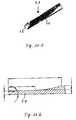
- FIG. 10 is a perspective side view of an endoawl as a guide element for a milling chisel
- FIG. 10.1 is an enlarged representation of the distal tip of the endoawl of FIG. 10 ;
- FIG. 11 is a perspective representation of an endospatula sharpened at the distal end as a guide for a milling chisel;
- FIG. 11.1 shows an enlarged distal end of the endospatula of FIG. 11 ;
- FIG. 11.2 shows a longitudinal section through the distal end of an endospatula
- FIG. 12 is a perspective representation of an endoelevator with blunted distal end as a guide for a milling chisel;
- FIG. 12.1 is an enlarged representation of the distal end of the endoelevator of FIG. 12 ;
- FIG. 12.2 is an enlarged longitudinal section through the distal end of the endoelevator
- FIG. 13 is a side view of a milling chisel with hollow shank
- FIG. 13.1 is an enlarged side view of the distal end of the milling chisel of FIG. 13 ;
- FIG. 13.2 shows an enlarged longitudinal section through the distal end of the milling chisel of FIG. 13 ;
- FIGS. 14 . 1 - 14 . 3 are representations showing the interaction of endoawl, endospatula and endoelevator with a milling chisel of FIG. 13 ;
- FIG. 15 is a side view of a handle for connection to the above-stated tools.
- FIG. 1 shows in longitudinal section the lower area of a spinal column 1000 with vertebrae 1004 and the spinous process (Processus spinosus) 1005 extending backwards (dorsally) away therefrom, between which—in the cross-section shown—are located the vertebral holes (vertebral foramen) forming the spinal canal 1006 of the spinal column 1000 . Between the vertebrae 1004 there are located the intervertebral discs 1001 with their nucleus 1002 ( FIG. 2 ) and their ring (annulus) 1001 a.
- the intervertebral discs 1001 with their nucleus 1002 ( FIG. 2 ) and their ring (annulus) 1001 a.
- the vertebrae are connected together at the front (ventral) side of the spinal canal by the anterior longitudinal ligament 1007 (Ligamentum longitudinale anterius), while the posterior longitudinal ligament (Ligamentum longitudinale posterius) 1008 is located to the rear of the spinal canal 1006 , in front of the spinous processes 1005 , the posterior longitudinal ligament being connected only loosely to the vertebrae but firmly to the discs 1001 .
- Nerve tissue 1003 extends through the spinal canal 1006 , individual nerves 1009 ( FIG. 2 ) exiting laterally between the vertebrae 1004 .
- To the side of the spinal canal 1006 (concealed by the nerve tissue 1003 and therefore not visible in FIG. 1 ) there is in each case located a “yellow” ligament (Ligamentum flavum) which is located in each case between two vertebrae and stabilizes the spinal column.
- a bony growth 1010 on a transverse process (Processus transversus) 1011 of the vertebra 1004 towards the vertebral body or the disc is visible, which narrows access to the medial region of the spinal canal 1005 and prevents a hollow tube of sufficiently large diameter for introduction of an endoscope from being inserted.
- the cutting tool 2 according to the invention is constructed at its distal end for removal of the bony growth 1010 .
- an elongate guide element was initially introduced, over which, optionally in the context of a dilatation process, one or more cannulae, in particular a cannula with a distal end with generally tapered geometry relative to the axis of symmetry, were introduced, so preventing in particular the entraining of tissue located in the operation region to the region treated.
- the distal end may for example be flat in shape, but other shapes are also possible and known, provided that the end is more distal at a first part than at a second part, i.e. has a generally oblique shape with regard to the axis of symmetry of the cannula.
- edges which are defined by the wall of the cannula, are rounded, in order to counteract the risk of injury to tissue during introduction of the cannula.
- Working instruments or an optical probe or an endoscope are introduced through the hollow region of the cannula. In the latter case, this is so as to be able to obtain images of the working area.
- inlet and outlet channels may be provided in the cannula for rinsing through with pressurized water. This pressurized water is used to remove residues and to obtain a cleaner camera image of the operation region.
- An endoscope is an apparatus with a substantially cylindrical main body with an optical channel, which optionally comprises a light guide and through which light may exit from the distal end of the apparatus to illuminate the surrounding area and from there an image may enter, which may be observed directly at the proximal end by way of a microscope or indirectly using an image converter and a screen.
- the elongate main body of the endoscope in any case additionally comprises a hollow working channel, through which working instruments may be guided and introduced from the proximal end to the distal end.
- FIG. 2 shows introduction of a cutting tool according to the invention or a cutting cannula, as will be described in greater detail below, over an elongate guide element 101 from the side towards the spinal canal 1006 .
- the elongate element 101 is introduced through an incision in the skin of the patient into his/her body.
- the tapered round tip serves to push endogenous tissue to the side, so as to allow the introduction of a cannula for the endoscope, without that this causing damage within the body.
- the cannula has an internal diameter which corresponds roughly to the external diameter of the elongate element 101 . In this way, tissue is prevented from being pushed into an otherwise possible gap between the elongate element 101 and the cannula and severed.
- the elongate element 1001 is removed, such that the inside of the cannula is hollow.
- the inside of the cannula is used by the user as a working area and cutting instruments, optical probes (endoscopes), forceps etc. may be introduced.
- working channels may be present inside the probe, in order to create a flow of pressurized aqueous liquid, which serves to keep the endoscope clean, such that it is possible to see the operation region, and may be used to remove residues arising during the intervention.
- All instruments which are introduced into the cannula are elongate in shape.
- the hitherto known cutting instruments have an elongate cylindrical shape with an oblique, saw blade-shaped end, which simplifies cutting.
- the diameter of the cannula is limited for obvious reasons (restriction of tissue expansion and of the incision to be performed).
- the inside of the cannula merely allows the simultaneous introduction of an optical probe with an additional working channel for a cutting tool of very reduced diameter, which may not be very useful in meeting the requirements of cutting bone tissue.
- cutting of bone tissue proceeds blind, i.e. without the possibility of observing the soft tissue, which is clearly very dangerous, since nerve tissue can be irreparably damaged and the success of the intervention depends on the dexterity of the operating surgeon.
- the cannula according to the invention takes the form of a cannula-type cutting tool 2 .
- This has a distal end 22 bevelled relative to the axis of symmetry 25 of the cannula.
- the size of the cutting tool 2 allows introduction into the body in the above-described manner and simultaneously allows positioning of an optical probe through the inside thereof, in a similar manner to already known cannulae.
- the characteristic feature of the present invention is that the cutting tool 2 , which constitutes the core subject matter of the invention, has a cutting edge 26 at the most distal region of the distal end, i.e. at the end-face edge of the cannula wall 21 .
- the cutting edge 26 is located at the endface edge of the cannula wall results in the cutting tool 2 , which constitutes the subject matter of the invention, being able, like a cannula of the endoscopic systems of known type, to be introduced into the body. Then when an elongate element 101 is introduced, which fills the entire inside, the cutting edge 26 cannot sever the tissue, as is clear from FIG. 4 .
- the general oblique shape of the distal end of the cutting tool 2 allows a correct view of the region to be cut from the inside of the cannula-type cutting tool 2 out.
- the cutting edge 26 lies on the inner side of the cannula wall 21 . Moreover, the cutting edge 26 consists of a cut 27 in the cannula wall 21 , which extends obliquely relative to the outside of the wall towards the inside in the region of the distal end 22 of the tool 2 ( FIG. 3 , 4 ).
- FIG. 3.3 shows that a graduation 23 or scale is located on the inside of the extension of the cutting tool 2 , for example by means of etched-in transverse indentations.
- the edge of the end-face opening of the cutting tool 2 is rounded apart from in the area of the sharp edge 26 located at the front end face.
- the end face of the cutting tool 2 is not merely bevelled but rather in side view is initially arcuate from the proximal side of the opening and only flattens out obliquely in its distal end region, wherein it here preferably forms an angle of the order of 10 to 20° with the longitudinal axis or side wall.
- the diameter of a cannula-type cutting tool 2 according to the invention should be greater than 3 mm and preferably lie in the range from 5 to 7 mm.
- FIG. 5 shows an alternative configuration of the cutting tool 2 , which constitutes the subject matter of this invention.
- the cutting edge 26 is serrated and does not coincide with the inside of the cannula wall 21 .
- this tool does not cause cutting injuries to tissue either, if it is introduced in the ways described above.
- the opening of the distal end of the cutting tool 2 is defined by a plane. However, this opening may also assume other forms, such as for example a curved surface ( FIG. 3.3 ) etc.
- the cutting tools 2 may have a similar diameter to that of the outer cannulae of the prior art devices, but in particular and advantageously have a somewhat larger diameter, such that endoscopes with larger diameters than hitherto may also be used. In the case of a system according to the present invention, the cutting tool 2 combines the functions of the outer cannula and of the cutting tool.
- the system according to this invention is completed by an optical probe 1 (endoscope), which is located inside the cannula-type cutting tool 2 with the cutting edge 26 and has a working channel for tools.
- an optical probe 1 endoscope
- This external cannula 30 may be conformed to the cutting tool 2 with cutting edge 26 and correspond with regard to its configuration to known outer cannulae (not in its diameter).
- FIG. 6 shows a device of this type.
- pressurized fluid may for example be rinsed through the working channel, such that the dimensions of the working space through which the pressurized fluid is rinsed do not vary with the movement of the cutting tool 2 .
- the invention thus also has the advantage of being able to cut without impairing the working channels of the optical probe.
- endoscopic forceps are inserted through a working channel of the probe 1 .
- the system may have means 4 for allowing alternating movement of the cutting tool 2 , so as in this way to simplify cutting of the bone tissue.
- Various techniques are available for allowing this type of movement: pneumatic, magnetic, electrical, mechanical systems etc. Therefore, they will not be described in any further detail here.
- These means may include means of allowing movement lengthways relative to an axis of the cutting tool 2 or an alternating movement about an axis 25 of the tool, preferably with the swiveling movement being restricted to a radius of up to 15°, in particular less than 6° with regard to a neutral position, thus with a total swivel range of 30° or preferably up to 12°.
- the cutting tool 2 may have an internal diameter of between 2.7 mm and 7.3 mm, but preferably between 3.2 and 6.1 mm.
- the length of the cutting tool and the further means may correspond to those of the already known systems.
- the method according to the invention thus so far comprises the following:
- first of all at least one rod-shaped tool is introduced.
- a plurality of tubular dilating tools of increasing diameter are introduced one over the other, until finally the cutting tool according to the invention may be introduced.
- the dilating rods fitting closely inside the same are removed and then an endoscope is introduced through the cutting tool as far as the distal region of the cutting tool, such that the working area of the cutting edge of the cutting tool may be monitored.
- work with the cutting tool may proceed by rhythmic or cyclic percussion and swiveling to-and-fro, in order to remove a bony growth, a bony protrusion or the like.
- the invention firstly provides, in a first configuration according to the invention, an endoawl 6 , as illustrated in FIG. 10 .
- the endoawl 6 in FIG. 10 comprises a solid elongate rod with a pointed, sharp distal end 6 . 1 , a rear or proximal non-circular-symmetrical gripping end 6 . 2 , on which a handle may be non-rotatably mounted, and a graduation 6 . 3 likewise arranged in the rear or proximal area produced by lines in the form of indentations arranged at the circumference perpendicularly to the longitudinal axis.
- the endoawl 6 has a total length of between 300 mm and 400 mm, preferably 370 mm, a gripping end 6 . 2 of between 20 mm and 30 mm, preferably 25 mm, a length from the last distal graduation line to the tip of between 200 mm and 300 mm, preferably 250 mm, and a tip length of between 5 mm and 15 mm, preferably 10 mm.
- the diameter of an endoawl 6 according to the invention is between 2 mm and 3.5 mm, preferably in the range from 2.6 mm to 3 mm.
- the conical tip 6 .
- the endoawl 6 is anchored to internal material at the posterior longitudinal ligament by axially acting force, such as for example by means of hammers.
- the endoawl 6 may then serve to guide a milling chisel, as described further below.
- the endoawl 6 is introduced endoscopically with observation, i.e. through the working cavity of an endoscope, and anchored in place.
- the invention additionally or alternatively provides an endospatula 7 for anchoring purposes, as illustrated in FIGS. 11 and 11 . 1 .
- the endospatula 7 also comprises a solid, rod-type elongate cylindrical body. It is provided with the same gripping end 6 . 2 and the same graduation 6 . 3 as the endoawl 6 , for which reason the same reference numerals are also used.
- its distal end region 7 . 1 is configured markedly differently from the endoawl 6 .
- the distal end region firstly comprises an arcuate flattened portion 7 . 2 , which then develops into a sharp end-face edge 7 .
- the rounded flattened area starting from the cylindrical main part of the endospatula 7 , inclines not in a straight line, but rather in rounded manner with a radius of preferably 35 mm. This is adjoined as far as the distal end of the edge 7 . 3 of the endospatula 7 by a flat portion, which has approximately the thickness of half the diameter of the main portion of the endospatula 7 , with a length of 7 mm to 15 mm, preferably 10 mm.
- the bevel to the distal sharp edge 7 . 3 proceeds at an angle of approximately 25° to 35°, preferably 30° to the longitudinal axis of the endospatula 7 .
- FIGS. 12 , 12 . 1 and 12 . 2 show an “endoelevator” 8 , whose distal end may engage behind the posterior longitudinal ligament.
- identical parts are again designated with identical reference numerals, i.e. the proximal gripping end 6 . 2 and the graduation 6 . 3 .
- the endoelevator 8 is likewise constructed as a solid hollow shank with a diameter of the order stated above in relation to the endoawl. Its distal end region 8 .
- endoawl, endospatula and endoelevator are fixed in the region of the posterior longitudinal ligaments, in order to serve as guides for a milling chisel, as illustrated in FIGS. 13 , 13 . 1 and 13 . 2 .
- the milling chisel 9 comprises an extended hollow cylinder of a length which is somewhat less than the length of endoawl, endochisel, and endoelevator.
- the proximal end 9 . 1 (not explained here in any more detail) is provided with a coupling configuration, which allows non-rotatable, axially fixed coupling of a handle or rotary drive, like the coupling disclosed in DE 20 2005 016 761.4 U, to which reference is made and which is deemed to be part of the disclosure of the present application.
- the distal end 9 . 2 is provided with teeth 9 . 3 , the teeth tapering radially to a point, but over the circumference having a finite direction of extension, i.e. comprising a cutting edge 9 . 4 .
- the front tooth flank is axially parallel, while the rear tooth flank forms an angle with the axis of the order of 40° to 50°, preferably 45°.
- the cutting edge 9 . 4 is located on the outer circumference of the shell 9 . 5 of the milling chisel 9 .
- a graduation once again formed of indentations or notches extending perpendicularly to the axis in the circumferential direction, which, when the milling chisel 9 is inserted through the working cavity of an endoscope into the working area thereof, may be seen and observed by way of the lateral viewing optics at the distal end of the endoscope.
- FIGS. 14.1 to 14 . 3 show the interaction of a hollow-cylindrical milling chisel 9 with an endoawl 6 , an endospatula 7 or an endoelevator 8 , which in each case extend through the cavity of the milling chisel.
- FIG. 15 is a schematic representation of a handle with a drive inside it and a coupling corresponding to DE 20 2005 016 761.4 U.
- One of the tools 6 , 7 or 8 is advanced through the working channel of the endoscope extending through the cutting tool 2 as far as the longitudinal ligament at the level of the operation area and anchored there in the manner described, either by pushing in or squeezing between longitudinal ligament and bone material or by hooking behind the longitudinal ligament.
- the milling chisel 9 is pushed through the working channel of the endoscope over the tool 6 , 7 or 8 and, when it reaches its working or operation region, is set in rotation, such that material in the way of the teeth, such as bony growths or ligament cartilaginification, which press on nerves, may be removed.
- the internal diameter of the milling chisel 9 is here somewhat greater than the external diameter of the corresponding tool 6 , 7 or 8 , such that the milling chisel 9 is guided thereby but nevertheless slight lateral mobility is possible and therefore the operating surgeon is provided with a certain degree of working freedom.
Landscapes
- Health & Medical Sciences (AREA)
- Life Sciences & Earth Sciences (AREA)
- Surgery (AREA)
- Orthopedic Medicine & Surgery (AREA)
- Animal Behavior & Ethology (AREA)
- Veterinary Medicine (AREA)
- Public Health (AREA)
- Engineering & Computer Science (AREA)
- Biomedical Technology (AREA)
- Heart & Thoracic Surgery (AREA)
- Medical Informatics (AREA)
- Molecular Biology (AREA)
- General Health & Medical Sciences (AREA)
- Nuclear Medicine, Radiotherapy & Molecular Imaging (AREA)
- Oral & Maxillofacial Surgery (AREA)
- Dentistry (AREA)
- Physics & Mathematics (AREA)
- Pathology (AREA)
- Biophysics (AREA)
- Hematology (AREA)
- Vascular Medicine (AREA)
- Immunology (AREA)
- Neurology (AREA)
- Optics & Photonics (AREA)
- Radiology & Medical Imaging (AREA)
- Surgical Instruments (AREA)
- Endoscopes (AREA)
Applications Claiming Priority (4)
| Application Number | Priority Date | Filing Date | Title |
|---|---|---|---|
| ES200603026 | 2006-11-27 | ||
| ES200603026A ES2279733B1 (es) | 2006-11-27 | 2006-11-27 | Dispositivo para eliminacion de tejido en operaciones endoscopicas. |
| ES200603026/4 | 2006-11-27 | ||
| PCT/EP2007/010238 WO2008064842A2 (fr) | 2006-11-27 | 2007-11-24 | Dispositif et procédé pour intervention minimale invasive sur la colonne vertébrale |
Publications (2)
| Publication Number | Publication Date |
|---|---|
| US20110184234A1 US20110184234A1 (en) | 2011-07-28 |
| US8821378B2 true US8821378B2 (en) | 2014-09-02 |
Family
ID=38468513
Family Applications (1)
| Application Number | Title | Priority Date | Filing Date |
|---|---|---|---|
| US12/516,316 Active 2030-05-05 US8821378B2 (en) | 2006-11-27 | 2007-11-24 | Device and method for minimally invasive spinal intervention |
Country Status (7)
| Country | Link |
|---|---|
| US (1) | US8821378B2 (fr) |
| EP (1) | EP2096982B1 (fr) |
| JP (1) | JP5242585B2 (fr) |
| KR (1) | KR101451287B1 (fr) |
| CN (1) | CN101573069B (fr) |
| ES (2) | ES2279733B1 (fr) |
| WO (1) | WO2008064842A2 (fr) |
Cited By (29)
| Publication number | Priority date | Publication date | Assignee | Title |
|---|---|---|---|---|
| US9277928B2 (en) | 2013-03-11 | 2016-03-08 | Interventional Spine, Inc. | Method and apparatus for minimally invasive insertion of intervertebral implants |
| US9486149B2 (en) | 2011-03-10 | 2016-11-08 | Interventional Spine, Inc. | Method and apparatus for minimally invasive insertion of intervertebral implants |
| US9492194B2 (en) | 2011-03-10 | 2016-11-15 | Interventional Spine, Inc. | Method and apparatus for minimally invasive insertion of intervertebral implants |
| US9924979B2 (en) | 2014-09-09 | 2018-03-27 | Medos International Sarl | Proximal-end securement of a minimally invasive working channel |
| US9980737B2 (en) | 2014-08-04 | 2018-05-29 | Medos International Sarl | Flexible transport auger |
| US9993353B2 (en) | 2013-03-14 | 2018-06-12 | DePuy Synthes Products, Inc. | Method and apparatus for minimally invasive insertion of intervertebral implants |
| US10111712B2 (en) | 2014-09-09 | 2018-10-30 | Medos International Sarl | Proximal-end securement of a minimally invasive working channel |
| US10264959B2 (en) | 2014-09-09 | 2019-04-23 | Medos International Sarl | Proximal-end securement of a minimally invasive working channel |
| US10299838B2 (en) | 2016-02-05 | 2019-05-28 | Medos International Sarl | Method and instruments for interbody fusion and posterior fixation through a single incision |
| US10682130B2 (en) | 2015-09-04 | 2020-06-16 | Medos International Sarl | Surgical access port stabilization |
| US10786264B2 (en) | 2015-03-31 | 2020-09-29 | Medos International Sarl | Percutaneous disc clearing device |
| USRE48534E1 (en) | 2012-04-16 | 2021-04-27 | DePuy Synthes Products, Inc. | Detachable dilator blade |
| US11013530B2 (en) | 2019-03-08 | 2021-05-25 | Medos International Sarl | Surface features for device retention |
| US11045324B2 (en) | 2006-12-08 | 2021-06-29 | DePuy Synthes Products, Inc. | Method of implanting a curable implant material |
| US11051862B2 (en) | 2001-11-03 | 2021-07-06 | DePuy Synthes Products, Inc. | Device for straightening and stabilizing the vertebral column |
| US11129727B2 (en) | 2019-03-29 | 2021-09-28 | Medos International Sari | Inflatable non-distracting intervertebral implants and related methods |
| US11134987B2 (en) | 2011-10-27 | 2021-10-05 | DePuy Synthes Products, Inc. | Method and devices for a sub-splenius/supra-levator scapulae surgical access technique |
| US11219439B2 (en) | 2012-09-26 | 2022-01-11 | DePuy Synthes Products, Inc. | NIR/RED light for lateral neuroprotection |
| US11241252B2 (en) | 2019-03-22 | 2022-02-08 | Medos International Sarl | Skin foundation access portal |
| US11439380B2 (en) | 2015-09-04 | 2022-09-13 | Medos International Sarl | Surgical instrument connectors and related methods |
| US20220304709A1 (en) * | 2021-03-25 | 2022-09-29 | DePuy Synthes Products, Inc. | Lateral cortex penetrator |
| US11559328B2 (en) | 2015-09-04 | 2023-01-24 | Medos International Sarl | Multi-shield spinal access system |
| US11660082B2 (en) | 2011-11-01 | 2023-05-30 | DePuy Synthes Products, Inc. | Dilation system |
| US11672562B2 (en) | 2015-09-04 | 2023-06-13 | Medos International Sarl | Multi-shield spinal access system |
| US11737743B2 (en) | 2007-10-05 | 2023-08-29 | DePuy Synthes Products, Inc. | Dilation system and method of using the same |
| US11744447B2 (en) | 2015-09-04 | 2023-09-05 | Medos International | Surgical visualization systems and related methods |
| US11771517B2 (en) | 2021-03-12 | 2023-10-03 | Medos International Sarl | Camera position indication systems and methods |
| US11813026B2 (en) | 2019-04-05 | 2023-11-14 | Medos International Sarl | Systems, devices, and methods for providing surgical trajectory guidance |
| US12004960B2 (en) | 2020-12-28 | 2024-06-11 | DePuy Synthes Products, Inc. | Method and apparatus for minimally invasive insertion of intervertebral implants |
Families Citing this family (43)
| Publication number | Priority date | Publication date | Assignee | Title |
|---|---|---|---|---|
| US6793678B2 (en) | 2002-06-27 | 2004-09-21 | Depuy Acromed, Inc. | Prosthetic intervertebral motion disc having dampening |
| WO2008070863A2 (fr) | 2006-12-07 | 2008-06-12 | Interventional Spine, Inc. | Implant intervertébral |
| US8900307B2 (en) | 2007-06-26 | 2014-12-02 | DePuy Synthes Products, LLC | Highly lordosed fusion cage |
| KR101552476B1 (ko) | 2008-01-17 | 2015-09-11 | 신세스 게엠바하 | 팽창가능한 추간 임플란트 및 관련된 그 제조 방법 |
| CN102036623A (zh) | 2008-04-05 | 2011-04-27 | 斯恩蒂斯有限公司 | 可膨胀的椎间植入体 |
| FR2937239B1 (fr) * | 2008-10-17 | 2010-11-26 | Fournitures Hospitalieres Ind | Dispositif chirurgical, notamment pour la chirurgie du pied |
| US9526620B2 (en) | 2009-03-30 | 2016-12-27 | DePuy Synthes Products, Inc. | Zero profile spinal fusion cage |
| US9393129B2 (en) | 2009-12-10 | 2016-07-19 | DePuy Synthes Products, Inc. | Bellows-like expandable interbody fusion cage |
| US8979860B2 (en) | 2010-06-24 | 2015-03-17 | DePuy Synthes Products. LLC | Enhanced cage insertion device |
| US8845733B2 (en) | 2010-06-24 | 2014-09-30 | DePuy Synthes Products, LLC | Lateral spondylolisthesis reduction cage |
| AU2011271465B2 (en) | 2010-06-29 | 2015-03-19 | Synthes Gmbh | Distractible intervertebral implant |
| US9049986B2 (en) * | 2010-09-20 | 2015-06-09 | Spine View, Inc. | Cannulotome |
| US8449463B2 (en) * | 2010-10-08 | 2013-05-28 | K2M, Inc. | Lateral access system and method of use |
| US9402732B2 (en) | 2010-10-11 | 2016-08-02 | DePuy Synthes Products, Inc. | Expandable interspinous process spacer implant |
| JP5785061B2 (ja) * | 2011-10-26 | 2015-09-24 | 周 中村 | 経皮的内視鏡用骨切りノミ |
| DE102012008970B3 (de) * | 2012-05-03 | 2013-06-27 | Joimax Gmbh | Chirurgische Werkzeugeinrichtung |
| US20150342621A1 (en) * | 2014-05-29 | 2015-12-03 | Avery M. Jackson, III | Illuminated endoscopic pedicle probe with dynamic real time monitoring for proximity to nerves |
| US20150080755A1 (en) * | 2012-05-16 | 2015-03-19 | Avery M. Jackson, III | Illuminated Endoscopic Pedicle Probe With Electromyographic Monitoring |
| WO2014018098A1 (fr) | 2012-07-26 | 2014-01-30 | DePuy Synthes Products, LLC | Implant expansible |
| US20140067069A1 (en) | 2012-08-30 | 2014-03-06 | Interventional Spine, Inc. | Artificial disc |
| CN103126743B (zh) * | 2012-12-19 | 2015-05-20 | 池永龙 | 微视环锯 |
| US9717601B2 (en) | 2013-02-28 | 2017-08-01 | DePuy Synthes Products, Inc. | Expandable intervertebral implant, system, kit and method |
| US9522070B2 (en) | 2013-03-07 | 2016-12-20 | Interventional Spine, Inc. | Intervertebral implant |
| JP6280725B2 (ja) * | 2013-11-10 | 2018-02-14 | 周 中村 | 経皮的内視鏡用ラスパ |
| JP6165080B2 (ja) * | 2014-02-21 | 2017-07-19 | オリンパス株式会社 | マニピュレータシステムの初期化方法 |
| US11426290B2 (en) | 2015-03-06 | 2022-08-30 | DePuy Synthes Products, Inc. | Expandable intervertebral implant, system, kit and method |
| US9913727B2 (en) | 2015-07-02 | 2018-03-13 | Medos International Sarl | Expandable implant |
| US10085830B2 (en) * | 2016-05-13 | 2018-10-02 | Medos International Sarl | Device, system, and method for delivery of a tissue fixation device |
| WO2018002715A2 (fr) | 2016-06-28 | 2018-01-04 | Eit Emerging Implant Technologies Gmbh | Cages intervertébrales articulées à expansion et réglage angulaire |
| AU2017287886B2 (en) | 2016-06-28 | 2022-07-28 | Eit Emerging Implant Technologies Gmbh | Expandable, angularly adjustable intervertebral cages |
| US10537436B2 (en) | 2016-11-01 | 2020-01-21 | DePuy Synthes Products, Inc. | Curved expandable cage |
| US10888433B2 (en) | 2016-12-14 | 2021-01-12 | DePuy Synthes Products, Inc. | Intervertebral implant inserter and related methods |
| US10398563B2 (en) | 2017-05-08 | 2019-09-03 | Medos International Sarl | Expandable cage |
| US11344424B2 (en) | 2017-06-14 | 2022-05-31 | Medos International Sarl | Expandable intervertebral implant and related methods |
| US10940016B2 (en) | 2017-07-05 | 2021-03-09 | Medos International Sarl | Expandable intervertebral fusion cage |
| US11331091B2 (en) * | 2017-11-14 | 2022-05-17 | Endovision Co., Ltd. | Surgical instrument set for use during unilateral biportal endoscopy |
| US20190142407A1 (en) * | 2017-11-14 | 2019-05-16 | Endovision Co., Ltd. | Method of unilateral biportal endoscopy and diamond shaver used in same |
| US11457909B2 (en) * | 2017-11-14 | 2022-10-04 | Min Ho Jung | Sheath device for biportal endoscopic spinal surgery |
| US11446156B2 (en) | 2018-10-25 | 2022-09-20 | Medos International Sarl | Expandable intervertebral implant, inserter instrument, and related methods |
| US11426286B2 (en) | 2020-03-06 | 2022-08-30 | Eit Emerging Implant Technologies Gmbh | Expandable intervertebral implant |
| US11850160B2 (en) | 2021-03-26 | 2023-12-26 | Medos International Sarl | Expandable lordotic intervertebral fusion cage |
| US11752009B2 (en) | 2021-04-06 | 2023-09-12 | Medos International Sarl | Expandable intervertebral fusion cage |
| CN115137451B (zh) * | 2022-09-05 | 2022-11-29 | 北京博海康源医疗器械有限公司 | 用于切割骨外固定针道或固定钉道周围软组织的松解器 |
Citations (27)
| Publication number | Priority date | Publication date | Assignee | Title |
|---|---|---|---|---|
| EP0076409A1 (fr) | 1981-10-05 | 1983-04-13 | INDESIT INDUSTRIA ELETTRODOMESTICI ITALIANA S.p.A. | Dispositif pour ouvrir le couvercle d'un lave-vaisselle |
| US4625713A (en) | 1982-12-14 | 1986-12-02 | Olympus Optical Co. Ltd. | Instrument incorporated in a resectoscope |
| US5215526A (en) * | 1988-07-06 | 1993-06-01 | Ethicon, Inc. | Safety trocar |
| US5226426A (en) * | 1990-12-18 | 1993-07-13 | Inbae Yoon | Safety penetrating instrument |
| EP0585826A1 (fr) | 1992-09-02 | 1994-03-09 | Olympus Winter & Ibe Gmbh | Instrument médical pour canalisation tissulairée |
| US5569292A (en) * | 1995-02-01 | 1996-10-29 | Ethicon Endo-Surgery, Inc. | Surgical penetration instrument with transparent blades and tip cover |
| DE19547246C1 (de) | 1995-12-18 | 1997-03-20 | Riek Siegfried | Medizinische Nadel |
| US5674184A (en) * | 1994-03-15 | 1997-10-07 | Ethicon Endo-Surgery, Inc. | Surgical trocars with cutting electrode and viewing rod |
| US5792044A (en) * | 1996-03-22 | 1998-08-11 | Danek Medical, Inc. | Devices and methods for percutaneous surgery |
| US5797944A (en) * | 1992-11-12 | 1998-08-25 | Ethicon Endo-Surgery, Inc. | Visualization trocar |
| US5961522A (en) * | 1997-11-10 | 1999-10-05 | Mehdizadeh; Hamid M. | Laminectomy chisel and guide apparatus |
| US6228058B1 (en) * | 1997-04-03 | 2001-05-08 | Core Dynamics, Inc. | Sleeve trocar with penetration indicator |
| US20020016592A1 (en) | 1998-08-27 | 2002-02-07 | Branch Charles L. | Interbody fusion grafts and instrumentation |
| US20020052619A1 (en) * | 2000-06-13 | 2002-05-02 | Transue James A. | Dermal punches |
| US6682535B2 (en) * | 1999-06-16 | 2004-01-27 | Thomas Hoogland | Apparatus for decompressing herniated intervertebral discs |
| US6751875B2 (en) * | 2001-09-13 | 2004-06-22 | William Randolph Jones | High-speed, hand-held reciprocating method for cutting, carving, sawing, chiseling, filing, sanding, and engraving |
| EP1468652A1 (fr) | 2003-04-16 | 2004-10-20 | Paul M. Tsou | Dispositif pour la chirurgie rachidienne |
| WO2006044727A2 (fr) | 2004-10-15 | 2006-04-27 | Baxano, Inc. | Dispositifs et procedes d'ablation de tissus |
| WO2006091622A2 (fr) | 2005-02-22 | 2006-08-31 | Brian Kelleher | Methodes et dispositifs d'ancrage dans des tissus mous |
| US20060206118A1 (en) * | 2005-03-11 | 2006-09-14 | Kim Daniel H | Percutaneous endoscopic access tools for the spinal epidural space and related methods of treatment |
| DE202005016761U1 (de) | 2005-10-26 | 2006-11-30 | Joimax Gmbh | Facettengelenkfräser |
| WO2007035892A1 (fr) | 2005-09-21 | 2007-03-29 | Children's Hospital Medical Center | Instruments endoscopiques et methodes de pose d'implants rachidiens |
| US20070270898A1 (en) * | 2003-06-20 | 2007-11-22 | Lillehei Kevin O | Surgical Cannula |
| US7824327B2 (en) * | 2005-04-12 | 2010-11-02 | Tyco Healthcare Group Llp | Optical trocar with scope holding assembly |
| US7922723B2 (en) * | 1989-04-24 | 2011-04-12 | Gary Karlin Michelson | Method for using a surgical rongeur |
| US7947058B2 (en) * | 2001-09-24 | 2011-05-24 | Applied Medical Resources Corporation | Bladeless optical obturator |
| US7981133B2 (en) * | 1995-07-13 | 2011-07-19 | Maquet Cardiovascular, Llc | Tissue dissection method |
Family Cites Families (13)
| Publication number | Priority date | Publication date | Assignee | Title |
|---|---|---|---|---|
| US4610242A (en) * | 1984-04-18 | 1986-09-09 | Codman & Shurtleff, Inc. | Endoscope insertion cannula assembly |
| US4850354A (en) * | 1987-08-13 | 1989-07-25 | Baxter Travenol Laboratories, Inc. | Surgical cutting instrument |
| AU648107B2 (en) * | 1990-08-20 | 1994-04-14 | Suri A. Sastri | Tubular surgical cutting instruments |
| WO1993004629A1 (fr) * | 1991-08-29 | 1993-03-18 | Terwilliger Richard A | Instrument de biopsie avec bord tranchant affute et presentant une courbure |
| US5195541A (en) * | 1991-10-18 | 1993-03-23 | Obenchain Theodore G | Method of performing laparoscopic lumbar discectomy |
| JPH0719311A (ja) * | 1993-06-30 | 1995-01-20 | Osada Res Inst Ltd | 動力伝達機構 |
| US5615690A (en) * | 1995-02-15 | 1997-04-01 | Symbiosis Corporation | Tissue core biopsy cannula |
| US6042593A (en) * | 1995-11-20 | 2000-03-28 | Storz Endoskop Gmbh | Shaving or cutting instrument |
| US5807277A (en) * | 1995-12-15 | 1998-09-15 | Swaim; William R. | Biopsy hand tool for capturing tissue sample |
| AU722939B2 (en) * | 1996-04-10 | 2000-08-17 | Linvatec Corporation | Process for shaping and sharpening a rotatable surgical shaver blade |
| US5947989A (en) * | 1996-12-12 | 1999-09-07 | United States Surgical Corporation | Method and apparatus for transmyocardial revascularization |
| US5925036A (en) * | 1997-09-22 | 1999-07-20 | Maxwell, Iii; Ralph | Apparatus for repairing bone structure using laser |
| US20030055316A1 (en) * | 2001-09-19 | 2003-03-20 | Brannon James Kevin | Endoscopic bone debridement |
-
2006
- 2006-11-27 ES ES200603026A patent/ES2279733B1/es not_active Expired - Fee Related
-
2007
- 2007-11-24 EP EP07846809.7A patent/EP2096982B1/fr active Active
- 2007-11-24 CN CN200780048862.XA patent/CN101573069B/zh active Active
- 2007-11-24 US US12/516,316 patent/US8821378B2/en active Active
- 2007-11-24 KR KR1020097010782A patent/KR101451287B1/ko active IP Right Grant
- 2007-11-24 WO PCT/EP2007/010238 patent/WO2008064842A2/fr active Application Filing
- 2007-11-24 JP JP2009538626A patent/JP5242585B2/ja active Active
- 2007-11-24 ES ES07846809.7T patent/ES2581356T3/es active Active
Patent Citations (28)
| Publication number | Priority date | Publication date | Assignee | Title |
|---|---|---|---|---|
| EP0076409A1 (fr) | 1981-10-05 | 1983-04-13 | INDESIT INDUSTRIA ELETTRODOMESTICI ITALIANA S.p.A. | Dispositif pour ouvrir le couvercle d'un lave-vaisselle |
| US4625713A (en) | 1982-12-14 | 1986-12-02 | Olympus Optical Co. Ltd. | Instrument incorporated in a resectoscope |
| US5215526A (en) * | 1988-07-06 | 1993-06-01 | Ethicon, Inc. | Safety trocar |
| US7922723B2 (en) * | 1989-04-24 | 2011-04-12 | Gary Karlin Michelson | Method for using a surgical rongeur |
| US5226426A (en) * | 1990-12-18 | 1993-07-13 | Inbae Yoon | Safety penetrating instrument |
| EP0585826A1 (fr) | 1992-09-02 | 1994-03-09 | Olympus Winter & Ibe Gmbh | Instrument médical pour canalisation tissulairée |
| US5406940A (en) | 1992-09-02 | 1995-04-18 | Olympus Winter & Ibe Gmbh | Medical instrument for creating a tissue canal |
| US5797944A (en) * | 1992-11-12 | 1998-08-25 | Ethicon Endo-Surgery, Inc. | Visualization trocar |
| US5674184A (en) * | 1994-03-15 | 1997-10-07 | Ethicon Endo-Surgery, Inc. | Surgical trocars with cutting electrode and viewing rod |
| US5569292A (en) * | 1995-02-01 | 1996-10-29 | Ethicon Endo-Surgery, Inc. | Surgical penetration instrument with transparent blades and tip cover |
| US7981133B2 (en) * | 1995-07-13 | 2011-07-19 | Maquet Cardiovascular, Llc | Tissue dissection method |
| DE19547246C1 (de) | 1995-12-18 | 1997-03-20 | Riek Siegfried | Medizinische Nadel |
| US5792044A (en) * | 1996-03-22 | 1998-08-11 | Danek Medical, Inc. | Devices and methods for percutaneous surgery |
| US6228058B1 (en) * | 1997-04-03 | 2001-05-08 | Core Dynamics, Inc. | Sleeve trocar with penetration indicator |
| US5961522A (en) * | 1997-11-10 | 1999-10-05 | Mehdizadeh; Hamid M. | Laminectomy chisel and guide apparatus |
| US20020016592A1 (en) | 1998-08-27 | 2002-02-07 | Branch Charles L. | Interbody fusion grafts and instrumentation |
| US6682535B2 (en) * | 1999-06-16 | 2004-01-27 | Thomas Hoogland | Apparatus for decompressing herniated intervertebral discs |
| US20020052619A1 (en) * | 2000-06-13 | 2002-05-02 | Transue James A. | Dermal punches |
| US6751875B2 (en) * | 2001-09-13 | 2004-06-22 | William Randolph Jones | High-speed, hand-held reciprocating method for cutting, carving, sawing, chiseling, filing, sanding, and engraving |
| US7947058B2 (en) * | 2001-09-24 | 2011-05-24 | Applied Medical Resources Corporation | Bladeless optical obturator |
| EP1468652A1 (fr) | 2003-04-16 | 2004-10-20 | Paul M. Tsou | Dispositif pour la chirurgie rachidienne |
| US20070270898A1 (en) * | 2003-06-20 | 2007-11-22 | Lillehei Kevin O | Surgical Cannula |
| WO2006044727A2 (fr) | 2004-10-15 | 2006-04-27 | Baxano, Inc. | Dispositifs et procedes d'ablation de tissus |
| WO2006091622A2 (fr) | 2005-02-22 | 2006-08-31 | Brian Kelleher | Methodes et dispositifs d'ancrage dans des tissus mous |
| US20060206118A1 (en) * | 2005-03-11 | 2006-09-14 | Kim Daniel H | Percutaneous endoscopic access tools for the spinal epidural space and related methods of treatment |
| US7824327B2 (en) * | 2005-04-12 | 2010-11-02 | Tyco Healthcare Group Llp | Optical trocar with scope holding assembly |
| WO2007035892A1 (fr) | 2005-09-21 | 2007-03-29 | Children's Hospital Medical Center | Instruments endoscopiques et methodes de pose d'implants rachidiens |
| DE202005016761U1 (de) | 2005-10-26 | 2006-11-30 | Joimax Gmbh | Facettengelenkfräser |
Cited By (77)
| Publication number | Priority date | Publication date | Assignee | Title |
|---|---|---|---|---|
| US11051862B2 (en) | 2001-11-03 | 2021-07-06 | DePuy Synthes Products, Inc. | Device for straightening and stabilizing the vertebral column |
| US11045324B2 (en) | 2006-12-08 | 2021-06-29 | DePuy Synthes Products, Inc. | Method of implanting a curable implant material |
| US11737743B2 (en) | 2007-10-05 | 2023-08-29 | DePuy Synthes Products, Inc. | Dilation system and method of using the same |
| US11547443B2 (en) | 2011-03-10 | 2023-01-10 | DePuy Synthes Products, Inc. | Method and apparatus for minimally invasive insertion of intervertebral implants |
| US11484419B2 (en) | 2011-03-10 | 2022-11-01 | DePuy Synthes Products, Inc. | Method and apparatus for minimally invasive insertion of intervertebral implants |
| US11547442B2 (en) | 2011-03-10 | 2023-01-10 | DePuy Synthes Products, Inc. | Method and apparatus for minimally invasive insertion of intervertebral implants |
| US11484420B2 (en) | 2011-03-10 | 2022-11-01 | DePuy Synthes Products, Inc. | Method and apparatus for minimally invasive insertion of intervertebral implants |
| US11484418B2 (en) | 2011-03-10 | 2022-11-01 | DePuy Synthes Products, Inc. | Method and apparatus for minimally invasive insertion of intervertebral implants |
| US10111759B2 (en) | 2011-03-10 | 2018-10-30 | DePuy Synthes Products, Inc. | Method and apparatus for minimally invasive insertion of intervertebral implants |
| US10182842B2 (en) | 2011-03-10 | 2019-01-22 | DePuy Synthes Products, Inc. | Method and apparatus for minimally invasive insertion of intervertebral implants |
| US10743914B2 (en) | 2011-03-10 | 2020-08-18 | DePuy Snythes Products, Inc. | Method and apparatus for minimally invasive insertion of intervertebral implants |
| US9492194B2 (en) | 2011-03-10 | 2016-11-15 | Interventional Spine, Inc. | Method and apparatus for minimally invasive insertion of intervertebral implants |
| US9486149B2 (en) | 2011-03-10 | 2016-11-08 | Interventional Spine, Inc. | Method and apparatus for minimally invasive insertion of intervertebral implants |
| US10743915B2 (en) | 2011-03-10 | 2020-08-18 | DePuy Synthes Products, Inc. | Method and apparatus for minimally invasive insertion of intervertebral implants |
| US10729462B2 (en) | 2011-03-10 | 2020-08-04 | DePuy Synthes Products, Inc. | Method and apparatus for minimally invasive insertion of intervertebral implants |
| US10736661B2 (en) | 2011-03-10 | 2020-08-11 | DePuy Synthes Products, Inc. | Method and apparatus for minimally invasive insertion of intervertebral implants |
| US10743913B2 (en) | 2011-03-10 | 2020-08-18 | DePuy Synthes Products, Inc. | Method and apparatus for minimally invasive insertion of intervertebral implants |
| US10744004B2 (en) | 2011-03-10 | 2020-08-18 | DePuy Synthes Products, Inc. | Method and apparatus for minimally invasive insertion of intervertebral implants |
| US11134987B2 (en) | 2011-10-27 | 2021-10-05 | DePuy Synthes Products, Inc. | Method and devices for a sub-splenius/supra-levator scapulae surgical access technique |
| US11937797B2 (en) | 2011-10-27 | 2024-03-26 | DePuy Synthes Products, Inc. | Method and devices for a sub-splenius/supra-levator scapulae surgical access technique |
| US11911017B2 (en) | 2011-10-27 | 2024-02-27 | DePuy Synthes Products, Inc. | Method and devices for a sub-splenius/supra-levator scapulae surgical access technique |
| US11278323B2 (en) | 2011-10-27 | 2022-03-22 | DePuy Synthes Products, Inc. | Method and devices for a sub-splenius/supra-levator scapulae surgical access technique |
| US11241255B2 (en) | 2011-10-27 | 2022-02-08 | DePuy Synthes Products, Inc. | Method and devices for a sub-splenius/supra-levator scapulae surgical access technique |
| US11234736B2 (en) | 2011-10-27 | 2022-02-01 | DePuy Synthes Products, Inc. | Method and devices for a sub-splenius/supra-levator scapulae surgical access technique |
| US11660082B2 (en) | 2011-11-01 | 2023-05-30 | DePuy Synthes Products, Inc. | Dilation system |
| USRE48534E1 (en) | 2012-04-16 | 2021-04-27 | DePuy Synthes Products, Inc. | Detachable dilator blade |
| US11219439B2 (en) | 2012-09-26 | 2022-01-11 | DePuy Synthes Products, Inc. | NIR/RED light for lateral neuroprotection |
| US11559295B2 (en) | 2012-09-26 | 2023-01-24 | DePuy Synthes Products, Inc. | NIR/red light for lateral neuroprotection |
| US11759329B2 (en) | 2013-03-11 | 2023-09-19 | DePuy Synthes Products, Inc. | Method and apparatus for minimally invasive insertion of intervertebral implants |
| US9277928B2 (en) | 2013-03-11 | 2016-03-08 | Interventional Spine, Inc. | Method and apparatus for minimally invasive insertion of intervertebral implants |
| US10918495B2 (en) | 2013-03-11 | 2021-02-16 | DePuy Synthes Products, Inc. | Method and apparatus for minimally invasive insertion of intervertebral implants |
| US10898341B2 (en) | 2013-03-11 | 2021-01-26 | DePuy Synthes Products, Inc. | Method and apparatus for minimally invasive insertion of intervertebral implants |
| US9855058B2 (en) | 2013-03-11 | 2018-01-02 | DePuy Synthes Products, Inc. | Method and apparatus for minimally invasive insertion of intervertebral implants |
| US10813772B2 (en) | 2013-03-11 | 2020-10-27 | DePuy Synthes Products, Inc. | Method and apparatus for minimally invasive insertion of intervertebral implants |
| US10898342B2 (en) | 2013-03-11 | 2021-01-26 | DePuy Synthes Products, Inc. | Method and apparatus for minimally invasive insertion of intervertebral implants |
| US9993353B2 (en) | 2013-03-14 | 2018-06-12 | DePuy Synthes Products, Inc. | Method and apparatus for minimally invasive insertion of intervertebral implants |
| US11590002B2 (en) | 2013-03-14 | 2023-02-28 | DePuy Synthes Products, Inc. | Method and apparatus for minimally invasive insertion of intervertebral implants |
| US10537443B2 (en) | 2013-03-14 | 2020-01-21 | DePuy Synthes Products, Inc. | Method and apparatus for minimally invasive insertion of intervertebral implants |
| US10863994B2 (en) | 2014-08-04 | 2020-12-15 | Medos International Sàrl | Flexible transport auger |
| US9980737B2 (en) | 2014-08-04 | 2018-05-29 | Medos International Sarl | Flexible transport auger |
| US11712252B2 (en) | 2014-08-04 | 2023-08-01 | Medos International Sarl | Flexible transport auger |
| US11213196B2 (en) | 2014-09-09 | 2022-01-04 | Medos International Sarl | Proximal-end securement of a minimally invasive working channel |
| US9924979B2 (en) | 2014-09-09 | 2018-03-27 | Medos International Sarl | Proximal-end securement of a minimally invasive working channel |
| US10786330B2 (en) | 2014-09-09 | 2020-09-29 | Medos International Sarl | Proximal-end securement of a minimally invasive working channel |
| US10111712B2 (en) | 2014-09-09 | 2018-10-30 | Medos International Sarl | Proximal-end securement of a minimally invasive working channel |
| US10264959B2 (en) | 2014-09-09 | 2019-04-23 | Medos International Sarl | Proximal-end securement of a minimally invasive working channel |
| US11464523B2 (en) | 2015-03-31 | 2022-10-11 | Medos International Sarl | Percutaneous disc clearing device |
| US10786264B2 (en) | 2015-03-31 | 2020-09-29 | Medos International Sarl | Percutaneous disc clearing device |
| US11344190B2 (en) | 2015-09-04 | 2022-05-31 | Medos International Sarl | Surgical visualization systems and related methods |
| US11712264B2 (en) | 2015-09-04 | 2023-08-01 | Medos International Sarl | Multi-shield spinal access system |
| US11439380B2 (en) | 2015-09-04 | 2022-09-13 | Medos International Sarl | Surgical instrument connectors and related methods |
| US10682130B2 (en) | 2015-09-04 | 2020-06-16 | Medos International Sarl | Surgical access port stabilization |
| US11331090B2 (en) | 2015-09-04 | 2022-05-17 | Medos International Sarl | Surgical visualization systems and related methods |
| US11950766B2 (en) | 2015-09-04 | 2024-04-09 | Medos International Sàrl | Surgical visualization systems and related methods |
| US10758220B2 (en) | 2015-09-04 | 2020-09-01 | Medos International Sarl | Devices and methods for providing surgical access |
| US10779810B2 (en) | 2015-09-04 | 2020-09-22 | Medos International Sarl | Devices and methods for surgical retraction |
| US11559328B2 (en) | 2015-09-04 | 2023-01-24 | Medos International Sarl | Multi-shield spinal access system |
| US11883064B2 (en) | 2015-09-04 | 2024-01-30 | Medos International Sarl | Multi-shield spinal access system |
| US11806043B2 (en) | 2015-09-04 | 2023-11-07 | Medos International Sarl | Devices and methods for providing surgical access |
| US11000312B2 (en) | 2015-09-04 | 2021-05-11 | Medos International Sarl | Multi-shield spinal access system |
| US11672562B2 (en) | 2015-09-04 | 2023-06-13 | Medos International Sarl | Multi-shield spinal access system |
| US11801070B2 (en) | 2015-09-04 | 2023-10-31 | Medos International Sarl | Surgical access port stabilization |
| US10987129B2 (en) | 2015-09-04 | 2021-04-27 | Medos International Sarl | Multi-shield spinal access system |
| US11793546B2 (en) | 2015-09-04 | 2023-10-24 | Medos International Sarl | Surgical visualization systems and related methods |
| US10874425B2 (en) | 2015-09-04 | 2020-12-29 | Medos International Sarl | Multi-shield spinal access system |
| US11744447B2 (en) | 2015-09-04 | 2023-09-05 | Medos International | Surgical visualization systems and related methods |
| US10869659B2 (en) | 2015-09-04 | 2020-12-22 | Medos International Sarl | Surgical instrument connectors and related methods |
| US11020153B2 (en) | 2016-02-05 | 2021-06-01 | Medos International Sarl | Method and instruments for interbody fusion and posterior fixation through a single incision |
| US10299838B2 (en) | 2016-02-05 | 2019-05-28 | Medos International Sarl | Method and instruments for interbody fusion and posterior fixation through a single incision |
| US11013530B2 (en) | 2019-03-08 | 2021-05-25 | Medos International Sarl | Surface features for device retention |
| US11241252B2 (en) | 2019-03-22 | 2022-02-08 | Medos International Sarl | Skin foundation access portal |
| US11129727B2 (en) | 2019-03-29 | 2021-09-28 | Medos International Sari | Inflatable non-distracting intervertebral implants and related methods |
| US11813026B2 (en) | 2019-04-05 | 2023-11-14 | Medos International Sarl | Systems, devices, and methods for providing surgical trajectory guidance |
| US12004960B2 (en) | 2020-12-28 | 2024-06-11 | DePuy Synthes Products, Inc. | Method and apparatus for minimally invasive insertion of intervertebral implants |
| US11771517B2 (en) | 2021-03-12 | 2023-10-03 | Medos International Sarl | Camera position indication systems and methods |
| US20220304709A1 (en) * | 2021-03-25 | 2022-09-29 | DePuy Synthes Products, Inc. | Lateral cortex penetrator |
| US11701132B2 (en) * | 2021-03-25 | 2023-07-18 | DePuy Synthes Products, Inc. | Lateral cortex penetrator |
Also Published As
| Publication number | Publication date |
|---|---|
| EP2096982A2 (fr) | 2009-09-09 |
| KR20090086561A (ko) | 2009-08-13 |
| ES2279733B1 (es) | 2008-08-16 |
| ES2279733A1 (es) | 2007-08-16 |
| KR101451287B1 (ko) | 2014-10-15 |
| WO2008064842A2 (fr) | 2008-06-05 |
| EP2096982B1 (fr) | 2016-04-13 |
| JP2010510841A (ja) | 2010-04-08 |
| US20110184234A1 (en) | 2011-07-28 |
| ES2581356T3 (es) | 2016-09-05 |
| CN101573069B (zh) | 2014-09-17 |
| CN101573069A (zh) | 2009-11-04 |
| JP5242585B2 (ja) | 2013-07-24 |
| WO2008064842A3 (fr) | 2008-11-20 |
Similar Documents
| Publication | Publication Date | Title |
|---|---|---|
| US8821378B2 (en) | Device and method for minimally invasive spinal intervention | |
| US6451022B2 (en) | Method of surgically reshaping the nasal bone | |
| EP0807415B1 (fr) | Outillage pour retenir une cavité en chirurgie osseuse, outillage pour retenir une cavité en chirurgie générale, système d'endoscopie chirurgical utilisant un outillage pour retenir une cavité | |
| US8623021B2 (en) | Facet joint reamer | |
| KR102056153B1 (ko) | 양방향 척추 내시경 수술용 시스장치 | |
| EP3205371A1 (fr) | Systèmes télescopiques de dilatation de tissus percutanés et procédés associés | |
| JP2013538624A (ja) | カニューレ挿入型切開刀 | |
| GB2430396A (en) | A surgical drill | |
| US8192443B2 (en) | Pedicle access device | |
| JP2000511788A (ja) | 経皮的外科手術用装置及び方法 | |
| JP2000505665A (ja) | 可撓性切削工具およびその使用方法 | |
| KR20150013545A (ko) | 교체 가능한 팁을 구비한 조명 내시경 패디클 프로브 | |
| CN105662504A (zh) | 肱二头肌肌腱固定术植入物和递送工具 | |
| US20220240916A1 (en) | Surgical instrument set for use during unilateral biportal endoscopy | |
| US20030018340A1 (en) | Method and apparatus for installing cannula | |
| US11547424B2 (en) | Instrument set for spinal operations | |
| US11759233B2 (en) | Optical cannula | |
| CN217853085U (zh) | 一种单侧双通道内镜ube专用套管 | |
| JP7456623B2 (ja) | 脊椎手術のための器具セット | |
| JPH0565180B2 (fr) |
Legal Events
| Date | Code | Title | Description |
|---|---|---|---|
| AS | Assignment |
Owner name: JOIMAX GMBH, GERMANY Free format text: ASSIGNMENT OF ASSIGNORS INTEREST;ASSIGNORS:MORGENSTERN LOPEZ, RUDOLF;RIES, WOLFGANG;SIGNING DATES FROM 20090326 TO 20090519;REEL/FRAME:023116/0423 |
|
| STCF | Information on status: patent grant |
Free format text: PATENTED CASE |
|
| MAFP | Maintenance fee payment |
Free format text: PAYMENT OF MAINTENANCE FEE, 4TH YR, SMALL ENTITY (ORIGINAL EVENT CODE: M2551) Year of fee payment: 4 |
|
| MAFP | Maintenance fee payment |
Free format text: PAYMENT OF MAINTENANCE FEE, 8TH YR, SMALL ENTITY (ORIGINAL EVENT CODE: M2552); ENTITY STATUS OF PATENT OWNER: SMALL ENTITY Year of fee payment: 8 |