US8807791B2 - Illuminating device with adjustable light beams and method for assembling the same - Google Patents

Illuminating device with adjustable light beams and method for assembling the same Download PDF

Info

Publication number
US8807791B2
US8807791B2 US13/452,065 US201213452065A US8807791B2 US 8807791 B2 US8807791 B2 US 8807791B2 US 201213452065 A US201213452065 A US 201213452065A US 8807791 B2 US8807791 B2 US 8807791B2
Authority
US
United States
Prior art keywords
light
emitting units
optical element
illuminating device
emitted
Prior art date
Legal status (The legal status is an assumption and is not a legal conclusion. Google has not performed a legal analysis and makes no representation as to the accuracy of the status listed.)
Active, expires
Application number
US13/452,065
Other versions
US20130208466A1 (en
Inventor
Chun-Ru Huang
Chien-Yueh Chen
Current Assignee (The listed assignees may be inaccurate. Google has not performed a legal analysis and makes no representation or warranty as to the accuracy of the list.)
AV Tech Corp
Original Assignee
AV Tech Corp
Priority date (The priority date is an assumption and is not a legal conclusion. Google has not performed a legal analysis and makes no representation as to the accuracy of the date listed.)
Filing date
Publication date
Application filed by AV Tech Corp filed Critical AV Tech Corp
Assigned to AV TECH CORPORATION reassignment AV TECH CORPORATION ASSIGNMENT OF ASSIGNORS INTEREST (SEE DOCUMENT FOR DETAILS). Assignors: CHEN, CHIEN-YUEH, HUANG, CHUN-RU
Publication of US20130208466A1 publication Critical patent/US20130208466A1/en
Application granted granted Critical
Publication of US8807791B2 publication Critical patent/US8807791B2/en
Active legal-status Critical Current
Adjusted expiration legal-status Critical

Links

Images

Classifications

    • FMECHANICAL ENGINEERING; LIGHTING; HEATING; WEAPONS; BLASTING
    • F21LIGHTING
    • F21VFUNCTIONAL FEATURES OR DETAILS OF LIGHTING DEVICES OR SYSTEMS THEREOF; STRUCTURAL COMBINATIONS OF LIGHTING DEVICES WITH OTHER ARTICLES, NOT OTHERWISE PROVIDED FOR
    • F21V5/00Refractors for light sources
    • F21V5/002Refractors for light sources using microoptical elements for redirecting or diffusing light
    • FMECHANICAL ENGINEERING; LIGHTING; HEATING; WEAPONS; BLASTING
    • F21LIGHTING
    • F21VFUNCTIONAL FEATURES OR DETAILS OF LIGHTING DEVICES OR SYSTEMS THEREOF; STRUCTURAL COMBINATIONS OF LIGHTING DEVICES WITH OTHER ARTICLES, NOT OTHERWISE PROVIDED FOR
    • F21V23/00Arrangement of electric circuit elements in or on lighting devices
    • F21V23/04Arrangement of electric circuit elements in or on lighting devices the elements being switches
    • FMECHANICAL ENGINEERING; LIGHTING; HEATING; WEAPONS; BLASTING
    • F21LIGHTING
    • F21VFUNCTIONAL FEATURES OR DETAILS OF LIGHTING DEVICES OR SYSTEMS THEREOF; STRUCTURAL COMBINATIONS OF LIGHTING DEVICES WITH OTHER ARTICLES, NOT OTHERWISE PROVIDED FOR
    • F21V5/00Refractors for light sources
    • F21V5/04Refractors for light sources of lens shape
    • HELECTRICITY
    • H05ELECTRIC TECHNIQUES NOT OTHERWISE PROVIDED FOR
    • H05BELECTRIC HEATING; ELECTRIC LIGHT SOURCES NOT OTHERWISE PROVIDED FOR; CIRCUIT ARRANGEMENTS FOR ELECTRIC LIGHT SOURCES, IN GENERAL
    • H05B45/00Circuit arrangements for operating light-emitting diodes [LED]
    • H05B45/30Driver circuits
    • FMECHANICAL ENGINEERING; LIGHTING; HEATING; WEAPONS; BLASTING
    • F21LIGHTING
    • F21VFUNCTIONAL FEATURES OR DETAILS OF LIGHTING DEVICES OR SYSTEMS THEREOF; STRUCTURAL COMBINATIONS OF LIGHTING DEVICES WITH OTHER ARTICLES, NOT OTHERWISE PROVIDED FOR
    • F21V3/00Globes; Bowls; Cover glasses
    • FMECHANICAL ENGINEERING; LIGHTING; HEATING; WEAPONS; BLASTING
    • F21LIGHTING
    • F21VFUNCTIONAL FEATURES OR DETAILS OF LIGHTING DEVICES OR SYSTEMS THEREOF; STRUCTURAL COMBINATIONS OF LIGHTING DEVICES WITH OTHER ARTICLES, NOT OTHERWISE PROVIDED FOR
    • F21V7/00Reflectors for light sources
    • F21V7/04Optical design
    • F21V7/06Optical design with parabolic curvature
    • FMECHANICAL ENGINEERING; LIGHTING; HEATING; WEAPONS; BLASTING
    • F21LIGHTING
    • F21VFUNCTIONAL FEATURES OR DETAILS OF LIGHTING DEVICES OR SYSTEMS THEREOF; STRUCTURAL COMBINATIONS OF LIGHTING DEVICES WITH OTHER ARTICLES, NOT OTHERWISE PROVIDED FOR
    • F21V7/00Reflectors for light sources
    • F21V7/04Optical design
    • F21V7/07Optical design with hyperbolic curvature
    • FMECHANICAL ENGINEERING; LIGHTING; HEATING; WEAPONS; BLASTING
    • F21LIGHTING
    • F21VFUNCTIONAL FEATURES OR DETAILS OF LIGHTING DEVICES OR SYSTEMS THEREOF; STRUCTURAL COMBINATIONS OF LIGHTING DEVICES WITH OTHER ARTICLES, NOT OTHERWISE PROVIDED FOR
    • F21V7/00Reflectors for light sources
    • F21V7/04Optical design
    • F21V7/08Optical design with elliptical curvature
    • FMECHANICAL ENGINEERING; LIGHTING; HEATING; WEAPONS; BLASTING
    • F21LIGHTING
    • F21YINDEXING SCHEME ASSOCIATED WITH SUBCLASSES F21K, F21L, F21S and F21V, RELATING TO THE FORM OR THE KIND OF THE LIGHT SOURCES OR OF THE COLOUR OF THE LIGHT EMITTED
    • F21Y2105/00Planar light sources
    • F21Y2105/10Planar light sources comprising a two-dimensional array of point-like light-generating elements
    • F21Y2105/12Planar light sources comprising a two-dimensional array of point-like light-generating elements characterised by the geometrical disposition of the light-generating elements, e.g. arranging light-generating elements in differing patterns or densities
    • FMECHANICAL ENGINEERING; LIGHTING; HEATING; WEAPONS; BLASTING
    • F21LIGHTING
    • F21YINDEXING SCHEME ASSOCIATED WITH SUBCLASSES F21K, F21L, F21S and F21V, RELATING TO THE FORM OR THE KIND OF THE LIGHT SOURCES OR OF THE COLOUR OF THE LIGHT EMITTED
    • F21Y2115/00Light-generating elements of semiconductor light sources
    • F21Y2115/10Light-emitting diodes [LED]

Abstract

An illuminating device with adjustable light beams and a method for assembling the same. The light-emitting units are disposed on the substrate. The optical element is disposed in the path of a light emitted by at least one of the light-emitting units. The driving unit drives a first or second set of the light-emitting units, wherein a light beam formed by light that is emitted by the first set of the light-emitting units and passes through the optical element has a different shape or projection angle from a light beam formed by light that is emitted by the second set of the light-emitting units and passes through the optical element.

Description

CROSS-REFERENCE TO RELATED APPLICATION
This application claims the benefit of Taiwan Patent Application No. 101104805, filed on Feb. 14, 2012, in the Taiwan Intellectual Property Office, the disclosure of which is incorporated herein in its entirety by reference.
BACKGROUND OF THE DISCLOSURE
1. Field of the Invention
The present invention relates to an illuminating device, and more particularly, to an illuminating device with adjustable light beams, wherein the illuminating device is provided with variable lights and thereby forms light beams in adjustable shapes or projection angles, and a method for assembling the same.
2. Description of the Related Art
Under encountering the scarcity of resources on the earth, energy saving technology is widely developed. Light-emitting diodes acting as light sources have high efficiency, long life spans, difficult to damage and low energy consumption and thus become one of the recent hot topics. Accordingly, the light-emitting diodes have been widely applied to illuminating devices, indicator lights of electric apparatuses, traffic lights, back light sources and so on.
However, the light-emitting diode or illuminating unit of prior art projects light in a fixed angle at shipment, and the angle cannot be changed after delivery. For adjusting the angles, a mechanically movable lens can be set in front of the light-emitting diode, but its manufacturing process steps are increased with inconvenience.
Therefore, it is a demand to overcome the illuminating unit of prior art projecting light only in a fixed angle, to overcome the mechanically movable optical element of prior art set for controlling projection angles, and to provide an improved illuminating device forming light beams in adjustable shapes, projection angles and intensities by electronically controlling illuminating units in specific regions to sequentially or randomly emit light passing through an optical element.
SUMMARY OF THE INVENTION
In order to improve the above-mentioned problems of prior art, the present invention is directed to an illuminating device with adjustable light beams, wherein the illuminating device has light-emitting units selected to emit light and thereby forms light beams in adjustable shapes or projection angles.
The present invention proposes an illuminating device with adjustable light beams. The illuminating device comprises a substrate, multiple light-emitting units, an optical element and a driving unit. The light-emitting units are disposed on the substrate. The optical element is disposed in the path of a light emitted by at least one of the light-emitting units. The driving unit drives a first or second set of the light-emitting units, wherein a light beam formed by light that is emitted by the first set of the light-emitting units and passes through the optical element has a different shape or projection angle from a light beam formed by light that is emitted by the second set of the light-emitting units and passes through the optical element.
In one embodiment, the light-emitting units disposed on the substrate are arranged in multiple rings.
In one embodiment, the light-emitting units arranged in the innermost one of the rings are defined as the first set thereof, and project light in an angle less than a preset angle.
In one embodiment, the light-emitting units arranged in the outermost one of the rings are defined as the second set thereof, and project light in an angle greater than a preset angle.
In one embodiment, the light-emitting units disposed on the substrate are arranged in a rectangle.
In one embodiment, the light beam formed by the light that is emitted by the first set of the light-emitting units and passes through the optical element has a different intensity from the light beam formed by the light that is emitted by the second set of the light-emitting units and passes through the optical element.
In one embodiment, the optical element has an optical surface containing a sphere or not containing a sphere, a Fresnel optical surface or a microstructured optical surface.
In one embodiment, the optical element comprises a lens, a reflector or a refraction plate.
In one embodiment, the reflector comprises a parabolic reflector, an elliptical reflector or a hyperboloid reflector.
In one embodiment, the refraction plate has a teeth shape, a trapezoidal shape, a pillar shape or a globe shape.
The present invention proposes a method for assembling an illuminating device. The method comprises the following steps: providing a substrate; disposing multiple light-emitting units on the substrate; disposing an optical element in the path of a light emitted by at least one of the light-emitting units; and selectively driving a first or second set of the light-emitting units using a driving unit, wherein a light beam formed by light that is emitted by the first set of the light-emitting units and passes through the optical element has a different shape or projection angle from a light beam formed by light that is emitted by the second set of the light-emitting units and passes through the optical element.
In accordance with the present invention, the illuminating device with adjustable light beams and the method for assembling the same have the following advantages:
(1) In accordance with the present invention, the illuminating device with adjustable light beams and the method for assembling the same overcome the illuminating unit of prior art projecting light only in a fixed angle.
(2) In accordance with the present invention, the illuminating device with adjustable light beams and the method for assembling the same overcome the mechanically movable optical element of prior art set for controlling projection angles.
(3) In accordance with the present invention, the illuminating device with adjustable light beams and the method for assembling the same form light beams in adjustable projection angles by electronically controlling illuminating units in specific regions to sequentially or randomly emit light passing through an optical element.
The accompanying drawings are included to provide a further understanding of the invention, and are incorporated as a part of this specification. The drawings illustrate embodiments of the invention and, together with the description, serve to explain the principles of the invention.
BRIEF DESCRIPTION OF THE DRAWINGS
FIG. 1 is a first schematic view of an illuminating device in accordance with a first embodiment of the present invention.
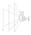
FIG. 2 is a second schematic view of an illuminating device in accordance with a first embodiment of the present invention.
FIG. 3 is a third schematic view of an illuminating device in accordance with a first embodiment of the present invention.
FIG. 4 is a first schematic view of an illuminating device in accordance with a second embodiment of the present invention.
FIG. 5 is a second schematic view of an illuminating device in accordance with a second embodiment of the present invention.
FIG. 6 is a third schematic view of an illuminating device in accordance with a second embodiment of the present invention.
FIG. 7 is a flow chart of assembling an illuminating device in accordance with the present invention.
DETAILED DESCRIPTION OF THE PREFERRED EMBODIMENTS
Illustrative embodiments accompanying with figures are now described below to lead the characteristics, contents, advantages and effects of the invention to be understood by the Examiner. Figures are illustrated only for explanation, but are not drawn to scale and precise arrangement, and thus the scope of the invention should not be limited by the scale and arrangement illustrated in the figures.
The following illustrations with accompanying figures are embodiments for describing an illuminating device with adjustable light beams and a method for assembling the same. In the following embodiments, same elements are indicated by same reference numbers.
FIGS. 1, 2 and 3 are first, second and third schematic views of an illuminating device in accordance with a first embodiment of the present invention. Referring to FIGS. 1, 2 and 3, multiple illuminating units 12 can be incandescent lamps, light-emitting diodes (LED) or high intensity discharge (HID) lamps. In accordance with this embodiment, the illuminating units 12 are multiple light-emitting diodes. Referring to FIG. 1, the light-emitting diodes 121 are disposed on a substrate 11 in a specific pattern, like arrangement in one or more rings in this embodiment, wherein the arrangement and number of the rings are not limited in this way, wherein the light-emitting diodes 121 are electrically connected to the substrate 11. The light-emitting diodes 121 arranged in the innermost one of the rings are defined as a first set of the illuminating units 12. The light-emitting diodes 121 arranged close to the innermost one of the rings are defined as a second set of the illuminating units 12. The light-emitting diodes 121 arranged in the outermost one of the rings are defined as a third set of the illuminating units 12. A driving unit 14 selectively drives the first or second set of the light-emitting units 12 to emit light in specific patterns.
Referring to FIG. 2, an optical element 13 can be disposed over the substrate 11 and the illuminating units 12. The optical element 13 has a distance to the substrate 11 or each illuminating units 12, designed based on demand, and is set in the path of a light emitted by at least one of the light-emitting diodes 121. The distance shown in Figures is an example, not drawn to scale, and thus should not be interpreted based on a proportion in Figures and limited to the scope of the invention. The optical element 13 can be a lens, reflector or refraction plate. In the embodiment, the optical element 13 is a lens. With regards to the reflector, it can be a parabolic reflector, elliptical reflector or hyperboloid reflector. With regards to the refraction plate, it may have a teeth shape, trapezoidal shape, pillar shape or globe shape.
Referring to FIGS. 1 and 3, under controlling the illuminating units 12 by the driving unit 14, the light-emitting diodes 121 in different regions can be sequentially or randomly selected to emit light in different fixed angles or scopes. For example, the first set of the light-emitting diodes 121 driven by the driving unit 14 can emit light in an angle of 30 degrees, that is, in the smallest scope. The third set of the light-emitting diodes 121 driven by the driving unit 14 can emit light in an angle of 45 degrees, that is, in the largest scope. However, light emitted in a fixed angle has a limited illumination scope, and thus has a restricted application. The optical element 13 is set over the illuminating units 12 and the substrate 11. Thereby, light emitted by the illuminating units 12 can pass through the optical element 13 refracting the light, and then light beams can be emitted in different angles.
Referring to FIG. 3, light emitted in an angle of 30 degrees by the first set of the light-emitting diodes 121 arranged in the innermost ring passes through the optical element 13, and then refracts in a projection angle of 50 degrees to form a circle light beam. Light emitted in an angle of 20 degrees by the second set of the light-emitting diodes 121 arranged in the second ring passes through the optical element 13, and then refracts in a projection angle of 90 degrees to form another circle light beam. Light emitted in an angle of 45 degrees by the third set of the light-emitting diodes 121 arranged in the outermost ring passes through the optical element 13, and then refracts in a projection angle of 120 degrees to form the other circle light beam. The light beams have refraction angles that vary with the material of the optical element 13. The light-emitting diodes 121 and the sets thereof can be alternatively arranged based on demand, and the driving unit 14 drives the selected set of the light-emitting units 12 individually to emit lights such that the lights passing through the optical element 13 can form different light beams having different shapes or projection angles.
In reference to the first embodiment, a second embodiment is alternatively proposed as below.
FIGS. 4, 5 and 6 are first, second and third schematic views of an illuminating device in accordance with a second embodiment of the present invention. Referring to FIGS. 4, 5 and 6, multiple illuminating units 12 can be incandescent lamps, light-emitting diodes (LED) or high intensity discharge (HID) lamps. In accordance with this embodiment, the illuminating units 12 are multiple light-emitting diodes. Referring to FIG. 4, the light-emitting diodes 121 are disposed on a substrate 11 in a specific pattern, like arrangement in a rectangle in this embodiment, wherein the arrangement and number of the rings are not limited in this way, wherein the light-emitting diodes 121 are electrically connected to the substrate 11. The optical element 13 has a distance to the substrate 11 or each illuminating units 12, wherein the distance shown in Figures is an example and should not limited the scope of the present invention. The optical element 13 is set in the path of a light emitted by at least one of the light-emitting units 12. The optical element 13 has an optical surface containing a sphere or not containing a sphere, Fresnel optical surface or a microstructured optical surface. The optical element 13 can be a lens, reflector or refraction plate. In the embodiment, the optical element 13 is a lens. The driving unit 14 drives the illuminating units 12 such that the light-emitting diodes 121 can be electrically controlled in sequence or random to emit light in fixed angles or scopes.
Referring to FIG. 5, under controlling the illuminating units 12 by the driving unit 14, the light-emitting diodes 121 in different regions can be sequentially or randomly selected to emit light in different fixed angles. The optical element 13 is set over the illuminating units 12 and the substrate 11. Thereby, light emitted by the illuminating units 12 can pass through the optical element 13 refracting the light, and then light beams can be emitted in different projection angles.
For example, referring to FIG. 6, in the 25 light emitting diodes 121 arranged in a rectangle, the third one from the right side in the third row is defined as a first set, the second one from the right side in the third row and the second one from the left side in the third row are defined as a second set, and the first one from the right side in the third row and the first one from the left side in the third row are defined as a third set. As shown in Figures, light emitted in an angle of 21 degrees by the first set of the light-emitting diodes 121 arranged at the center in the third row passes through the optical element 13, and then refracts in a projection angle of 50 degrees to form a light beam. Light emitted in an angle of 14 degrees by the second set of the light-emitting diodes 121 passes through the optical element 13, and then refracts in a projection angle of 90 degrees to form a light beam. Light emitted in an angle of 21 degrees by the third set of the light-emitting diodes 121 passes through the optical element 13, and then refracts in a projection angle of 120 degrees to form a light beam. The light beams have refraction angles that vary with the material of the optical element 13. The sets of the light-emitting diodes 121 of the illuminating device 2 may have alternative positions based on demand. As shown in Figures, light emitted by the first, second and third sets of the light-emitting diodes 121 passes through the optical element 13 so as to form variable light beams each in the shape of a knife edge.
Besides, the intensity of light emitted by the illuminating units 12 can be adjusted by electrically controlling currents output from the driving unit 14. Thereby, the illuminating units 12 can be designed with multiple scenarios including relatively bright or dark ones arranged in the center, relatively bright or dark ones arranged in the outer side and uniform bright ones arranged in the center and outer side. For example, a wide-angle camera has a wide angle of view, but serious image distortion and dark corners could occur. The dark corners can be corrected using the driving unit 14 of the present invention to control light emitted by the illuminating units 12.
For clarity, the method for assembling the illuminating device in accordance with the present invention are interpreted as below:
FIG. 7 is a flow chart of assembling an illuminating device in accordance with the present invention. Referring to FIG. 7, a method for assembling the illuminating device includes the following steps:
Step S11 is providing a substrate.
Step S12 is disposing multiple light-emitting units on the substrate.
Step S13 is disposing an optical element in the path of a light emitted by at least one of the light-emitting units.
Step S14 is selectively driving a first or second set of the light-emitting units using a driving unit.
It is noted that a light beam formed by light that is emitted by the first set of the light-emitting units and passes through the optical element has a different shape or projection angle from a light beam formed by light that is emitted by the second set of the light-emitting units and passes through the optical element.
In the above description for the illuminating device, the method for assembling the same is also described and the similar description is not repeated herein.
Illustrative embodiments accompanying with figures are above described but addition, modification or replacement applied to the embodiments of the present invention is within the scope of the claims. The skilled in the art would understand the invention can be realized with modification of multiple structures, arrangements, proportions and elements.

Claims (18)

What is claimed is:
1. An illuminating device with adjustable light beams, comprising:
a substrate;
multiple light-emitting units disposed on the substrate;
an optical element disposed in the path of a light emitted by at least one of the light-emitting units; and
a driving unit driving a first or second set of the light-emitting units, wherein a light beam formed by light that is emitted by the first set of the light-emitting units and passes through the optical element has a different shape or projection angle from a light beam formed by light that is emitted by the second set of the light-emitting units and passes through the optical element;
wherein the light beam formed by the light that is emitted by the first set of the light-emitting units and passes through the optical element has a different intensity from the light beam formed by the light that is emitted by the second set of the light-emitting units and passes through the optical element.
2. The illuminating device of claim 1, wherein the light-emitting units disposed on the substrate are arranged in multiple rings.
3. The illuminating device of claim 2, wherein the light-emitting units arranged in the innermost one of the rings are defined as the first set thereof and project light in an angle less than a preset angle.
4. The illuminating device of claim 2, wherein the light-emitting units arranged in the outermost one of the rings are defined as the second set thereof and project light in an angle greater than a preset angle.
5. The illuminating device of claim 1, wherein the light-emitting units disposed on the substrate are arranged in a rectangle.
6. The illuminating device of claim 1, wherein the optical element has an optical surface containing a sphere or not containing a sphere, a Fresnel optical surface or a microstructured optical surface.
7. The illuminating device of claim 1, wherein the optical element comprises a lens, reflector or refraction plate.
8. The illuminating device of claim 7, wherein the reflector comprises a parabolic reflector, an elliptical reflector or a hyperboloid reflector.
9. The illuminating device of claim 7, wherein the refraction plate has a teeth shape, a trapezoidal shape, a pillar shape or a globe shape.
10. A method for assembling an illuminating device, comprising:
providing a substrate;
disposing multiple light-emitting units on the substrate;
disposing an optical element in the path of a light emitted by at least one of the light-emitting units; and
selectively driving a first or second set of the light-emitting units using a driving unit, wherein a light beam formed by light that is emitted by the first set of the light-emitting units and passes through the optical element has a different shape or projection angle from a light beam formed by light that is emitted by the second set of the light-emitting units and passes through the optical element;
wherein the light beam formed by the light that is emitted by the first set of the light-emitting units and passes through the optical element has a different intensity from the light beam formed by the light that is emitted by the second set of the light-emitting units and passes through the optical element.
11. The method of claim 10, wherein the light-emitting units disposed on the substrate are arranged in multiple rings.
12. The method of claim 11, wherein the light-emitting units arranged in the innermost one of the rings are defined as the first set thereof and project light in an angle less than a preset angle.
13. The method of claim 11, wherein the light-emitting units arranged in the outermost one of the rings are defined as the second set thereof and project light in an angle greater than a preset angle.
14. The method of claim 10, wherein the light-emitting units disposed on the substrate are arranged in a rectangle.
15. The method of claim 10, wherein the optical element has an optical surface containing a sphere or not containing a sphere, a Fresnel optical surface or a microstructured optical surface.
16. The method of claim 10, wherein the optical element comprises a lens, a reflector or a refraction plate.
17. The method of claim 16, wherein the reflector comprises a parabolic reflector, an elliptical reflector or a hyperboloid reflector.
18. The method of claim 16, wherein the refraction plate has a teeth shape, a trapezoidal shape, a pillar shape or a globe shape.
US13/452,065 2012-02-14 2012-04-20 Illuminating device with adjustable light beams and method for assembling the same Active 2032-11-04 US8807791B2 (en)

Applications Claiming Priority (3)

Application Number Priority Date Filing Date Title
TW101104805A 2012-02-14
TW101104805A TWI491830B (en) 2012-02-14 2012-02-14 Illuminating device with variable light beam and assemble method thereof
TW101104805 2012-02-14

Publications (2)

Publication Number Publication Date
US20130208466A1 US20130208466A1 (en) 2013-08-15
US8807791B2 true US8807791B2 (en) 2014-08-19

Family

ID=48924569

Family Applications (1)

Application Number Title Priority Date Filing Date
US13/452,065 Active 2032-11-04 US8807791B2 (en) 2012-02-14 2012-04-20 Illuminating device with adjustable light beams and method for assembling the same

Country Status (3)

Country Link
US (1) US8807791B2 (en)
CN (1) CN103244843A (en)
TW (1) TWI491830B (en)

Cited By (2)

* Cited by examiner, † Cited by third party
Publication number Priority date Publication date Assignee Title
US20150357714A1 (en) * 2013-10-04 2015-12-10 Laird Technologies, Inc. Ground independent multi-band antenna assemblies
US20160223734A1 (en) * 2015-01-14 2016-08-04 E Ink Holdings Inc. Front light module and display module

Families Citing this family (5)

* Cited by examiner, † Cited by third party
Publication number Priority date Publication date Assignee Title
DE102015206471A1 (en) * 2015-04-10 2016-10-13 Osram Gmbh lighting device
US9699865B2 (en) * 2015-09-03 2017-07-04 Milwaukee Electric Tool Corporation Spotlight and method of controlling thereof
FR3047941B1 (en) * 2016-02-24 2019-11-29 Valeo Vision LIGHTING SYSTEM FOR THE CABIN OF A MOTOR VEHICLE
WO2019137909A1 (en) * 2018-01-10 2019-07-18 Signify Holding B.V. A led lamp and a method of controlling a led lamp
US11378241B1 (en) 2019-04-18 2022-07-05 Signify Holding B.V. Illumination device, lighting system and method of operating the illumination device

Citations (2)

* Cited by examiner, † Cited by third party
Publication number Priority date Publication date Assignee Title
US20100123600A1 (en) * 2008-11-18 2010-05-20 Lumination Llc Led signal light
US20100188301A1 (en) * 2007-07-17 2010-07-29 Kengo Kishimoto Lamp apparatus, antenna unit for lamp apparatus, communication system, and traffic signal controller

Family Cites Families (24)

* Cited by examiner, † Cited by third party
Publication number Priority date Publication date Assignee Title
CN1062665C (en) * 1994-01-27 2001-02-28 匡敖生 Photoconductive indicator
US5806965A (en) * 1996-01-30 1998-09-15 R&M Deese, Inc. LED beacon light
DE69803297T2 (en) * 1997-08-12 2002-08-22 Decoma Int Inc DOUBLE REFLECTIVE LENS
TW557344B (en) * 2000-07-11 2003-10-11 Mitsubishi Chem Corp Surface light source device
US7976211B2 (en) * 2001-08-24 2011-07-12 Densen Cao Light bulb utilizing a replaceable LED light source
US6746885B2 (en) * 2001-08-24 2004-06-08 Densen Cao Method for making a semiconductor light source
EP1453107A4 (en) * 2001-11-16 2008-12-03 Toyoda Gosei Kk Light-emitting diode, led light, and light apparatus
US20040114367A1 (en) * 2002-12-13 2004-06-17 Jui-Tuan Li Light emitting diode light bulb
TWM247762U (en) * 2003-12-24 2004-10-21 Chia-Yi Chen Light emitting diode of caution light
TWM248962U (en) * 2004-01-16 2004-11-01 Chia-Yi Chen Light LED apparatus
TWM256190U (en) * 2004-04-30 2005-02-01 Ruey Chiann Technology Co Ltd Photo-therapy beauty device
TWM259122U (en) * 2004-06-30 2005-03-11 Haozhen Entpr Co Ltd LED lamp
JP2006337739A (en) * 2005-06-02 2006-12-14 Canon Inc Illuminating apparatus
TWM283957U (en) * 2005-09-15 2005-12-21 Chin-Ming Chen Improved structure of light-emitting diode lamp bulb
CN101235942A (en) * 2007-01-30 2008-08-06 宁波安迪光电科技有限公司 LED illuminating apparatus
TWM349157U (en) * 2008-03-14 2009-01-11 Sensitive Electronic Co Ltd Improved LED light bulb
TWM343111U (en) * 2008-04-18 2008-10-21 Genius Electronic Optical Co Ltd Light base of high-wattage LED street light
CN101621054A (en) * 2008-07-01 2010-01-06 展晶科技(深圳)有限公司 LED light source device
US9425172B2 (en) * 2008-10-24 2016-08-23 Cree, Inc. Light emitter array
JP2012518254A (en) * 2009-02-17 2012-08-09 カオ グループ、インク. LED bulbs for space lighting
CN201382312Y (en) * 2009-02-26 2010-01-13 天台县海威机电有限公司 LED lamp module with glass mirror
JP4461197B1 (en) * 2009-04-27 2010-05-12 株式会社東芝 Planar illumination device and liquid crystal display device including the same
CN102045915A (en) * 2009-10-09 2011-05-04 鸿富锦精密工业(深圳)有限公司 LED lighting device
CN202132731U (en) * 2011-04-28 2012-02-01 英飞特光电(杭州)有限公司 Irradiation range adjustable LED (Light Emitting Diode) lamp

Patent Citations (2)

* Cited by examiner, † Cited by third party
Publication number Priority date Publication date Assignee Title
US20100188301A1 (en) * 2007-07-17 2010-07-29 Kengo Kishimoto Lamp apparatus, antenna unit for lamp apparatus, communication system, and traffic signal controller
US20100123600A1 (en) * 2008-11-18 2010-05-20 Lumination Llc Led signal light

Cited By (4)

* Cited by examiner, † Cited by third party
Publication number Priority date Publication date Assignee Title
US20150357714A1 (en) * 2013-10-04 2015-12-10 Laird Technologies, Inc. Ground independent multi-band antenna assemblies
US9595755B2 (en) * 2013-10-04 2017-03-14 Laird Technologies, Inc. Ground independent multi-band antenna assemblies
US20160223734A1 (en) * 2015-01-14 2016-08-04 E Ink Holdings Inc. Front light module and display module
US10416367B2 (en) * 2015-01-14 2019-09-17 E Ink Holdings Inc. Front light module and display module

Also Published As

Publication number Publication date
US20130208466A1 (en) 2013-08-15
TWI491830B (en) 2015-07-11
CN103244843A (en) 2013-08-14
TW201333365A (en) 2013-08-16

Similar Documents

Publication Publication Date Title
US8807791B2 (en) Illuminating device with adjustable light beams and method for assembling the same
US9470406B2 (en) Variable-beam light source and related methods
US7566155B2 (en) LED light system
US9933137B2 (en) Projecting light fixture with dynamic illumination of beam shaping object
US10393347B2 (en) Thin luminaire
EP2898259B1 (en) Variable-beam light source and related methods
CN110325787B (en) Luminaire with light guide
US20160381749A1 (en) Variable-beam light source and related methods
WO2012169117A1 (en) Optical unit
JP6096180B2 (en) Light emitting diode light source
JP2018528582A (en) Illumination system and illumination method
US10405388B2 (en) Variable-beam light source with mixing chamber
JP2013045530A (en) Light emitting device and lighting fixture
KR100991890B1 (en) Illuminator module using led
JP2011049001A (en) Lighting device
US20210140606A1 (en) Wide beam angle creation for solid state lighting
US10008137B2 (en) Illuminated sign with compartmented portion
CN103807627B (en) Light emitting module and illumination device with light emitting module
JP2010219038A (en) Device for removing overlap or locus of shadow of point-like source of light
US20140168998A1 (en) Lens structure of a light emitting diode
CN218153798U (en) Lighting device
CN220338298U (en) Lighting device
CN217559726U (en) Lighting device based on lens array
CN114938656A (en) Lighting device with white and non-white light sources
JP2010251005A (en) Led light source element and led luminaire using the same

Legal Events

Date Code Title Description
AS Assignment

Owner name: AV TECH CORPORATION, TAIWAN

Free format text: ASSIGNMENT OF ASSIGNORS INTEREST;ASSIGNORS:HUANG, CHUN-RU;CHEN, CHIEN-YUEH;REEL/FRAME:028082/0525

Effective date: 20120405

STCF Information on status: patent grant

Free format text: PATENTED CASE

MAFP Maintenance fee payment

Free format text: PAYMENT OF MAINTENANCE FEE, 4TH YR, SMALL ENTITY (ORIGINAL EVENT CODE: M2551)

Year of fee payment: 4

MAFP Maintenance fee payment

Free format text: PAYMENT OF MAINTENANCE FEE, 8TH YR, SMALL ENTITY (ORIGINAL EVENT CODE: M2552); ENTITY STATUS OF PATENT OWNER: SMALL ENTITY

Year of fee payment: 8