US8770264B2 - Device, gutter, method for tilt-casting components made of light metal, and components cast therewith - Google Patents
Device, gutter, method for tilt-casting components made of light metal, and components cast therewith Download PDFInfo
- Publication number
- US8770264B2 US8770264B2 US13/375,858 US201013375858A US8770264B2 US 8770264 B2 US8770264 B2 US 8770264B2 US 201013375858 A US201013375858 A US 201013375858A US 8770264 B2 US8770264 B2 US 8770264B2
- Authority
- US
- United States
- Prior art keywords
- casting
- mold
- channel
- casting mold
- outlets
- Prior art date
- Legal status (The legal status is an assumption and is not a legal conclusion. Google has not performed a legal analysis and makes no representation as to the accuracy of the status listed.)
- Expired - Fee Related
Links
Images


Classifications
-
- B—PERFORMING OPERATIONS; TRANSPORTING
- B22—CASTING; POWDER METALLURGY
- B22D—CASTING OF METALS; CASTING OF OTHER SUBSTANCES BY THE SAME PROCESSES OR DEVICES
- B22D23/00—Casting processes not provided for in groups B22D1/00 - B22D21/00
- B22D23/006—Casting by filling the mould through rotation of the mould together with a molten metal holding recipient, about a common axis
-
- B—PERFORMING OPERATIONS; TRANSPORTING
- B22—CASTING; POWDER METALLURGY
- B22D—CASTING OF METALS; CASTING OF OTHER SUBSTANCES BY THE SAME PROCESSES OR DEVICES
- B22D35/00—Equipment for conveying molten metal into beds or moulds
- B22D35/04—Equipment for conveying molten metal into beds or moulds into moulds, e.g. base plates, runners
Definitions
- the invention relates to an apparatus, a casting channel, and a method for tilt-casting of components made of light metal, as well as components cast with it.
- a method for casting components made of light metal, particularly of aluminum alloys, in accordance with the tilt-casting principle, as well as a corresponding apparatus for carrying out such a method, are known from DE 10 2004 015 649 B3.
- the melt is filled into a transverse run situated on the longitudinal side of a casting mold, using head-casting.
- the casting mold is first tilted about its longitudinal axis by an angle of 45° to 70°. Afterward, filling the liquid melt into the transverse run starts, until about 1 ⁇ 5 of the melt required for casting of the component has been filled into the transverse run, without the melt already flowing into the mold cavity of the casting mold. Subsequently, the casting mold is rotated out of the tilted position into the vertical, while continuously filling in further melt, in such a manner that the melt flows into the mold cavity along a casting mold wall.
- a disadvantage of the method disclosed in DE 10 2004 015 649 B3 consists in that the melt is at first only partly filled into the transverse run, before pouring of the melt into the coquille starts. In this connection, the risk can exist that temperature losses occur. It is furthermore disadvantageous that the remaining melt required for the casting process must be filled in continuously during tilt-casting, and therefore must be refilled into a casting pool of the transverse run, in very complicated manner, by means of a casting ladle. The casting ladle must therefore be guided along synchronously with the tilting of the casting mold, and is not available for any other or further casting process during this time.
- the invention is based on the task of making available an apparatus for casting of components made of light metal, according to the tilt-casting principle, with which apparatus new degrees of freedom or possibilities in process management for casting of components are created, eliminating the aforementioned disadvantages, thereby obtaining new component geometries, but particularly also new component properties, for example relating to the internal structure and/or the external composition of the components.
- the invention is furthermore based on the task of making available an apparatus for casting of components made of light metal, according to the tilt-casting principle, with which casting mold filling is achieved without significant technical effort, which filling avoids cavities, porosities and/or inclusions in the cast component, even in the case of complicated component geometries.
- the invention is furthermore based on the task of making available an apparatus for casting of components made of light metal, according to the tilt-casting principle, with which homogeneous filling of the casting mold with the melt is made possible without temperature losses, to a great extent.
- the invention is furthermore based on the task of making available an apparatus for casting of components made of light metal, according to the tilt-casting principle, with which a plurality of components can be cast at the same time, wherein the technical effort is kept low.
- an apparatus for casting of components preferably components made of light metal, according to the tilt-casting principle, which apparatus comprises a casting mold or coquille that can be tilted about its longitudinal axis, and a casting channel that is disposed on the casting mold, in the longitudinal direction of the latter.
- the casting channel has at least two outlets to the mold cavity, on its longitudinal side facing the casting mold, or at least one outlet, in each instance, to at least two mold cavities that are disposed next to one another and do not stand in a flow connection with one another.
- the casting channel furthermore has a subdivision device that is configured in such a manner that when the casting mold is tilted from a starting position into an end position, predetermined or specific volumes of the casting melt flow through the outlets into the mold cavity or into the mold cavities of the casting mold.
- the subdivided volumes within the casting channel stand in a flow connection in the region of the longitudinal side that lies opposite the outlets.
- the casting channel can be filled in particularly simple manner, in that the melt is filled in or introduced only at one location in or on the casting channel.
- the flow connection amounts to 1 ⁇ 4 to 3 ⁇ 4 in the transverse direction, preferably 1 ⁇ 3 to 2 ⁇ 3 of the length of the casting channel in the transverse direction.
- the wider the flow connection the faster and more uniformly the melt is distributed when it is filled into the casting channel, whereby no temperature losses are to be feared.
- a subdivision device provided according to the invention in the lower third or fourth of the casting channel, facing the mold cavity, is sufficient to divide the melt up among the outlets that are present, in predetermined amounts.
- the casting channel is disposed on the casting mold in such a manner that the casting channel is open upward in the starting position of the casting mold, in other words before tilting. In this way, the melt can be introduced into the casting channel in particularly simple manner.
- the subdivision device is funnel-shaped or shell-shaped in the region of the outlets.
- a funnel is configured to be quadragonal in a top view, whereby preferably, one side is missing if the casting channel is open on one side.
- a delimitation for subdivision is provided between the parallel outlets, within the casting channel, whereby the delimitation preferably drops toward the outlets, in each instance. In this way, the result is achieved that the melt flows through the outlet, in each instance, more uniformly during tilting of the casting mold.
- the outlet in each instance, is disposed at the low point of the subdivision device in the end position of the casting mold, in other words after tilting, and thereby the predetermined amount of melt flows completely into the casting mold, to the greatest possible extent.
- the casting mold, together with the casting channel can be tilted by up to 90°.
- a tilting range limited in this manner is sufficient to meet the requirements even of complicated component geometries.
- the casting channel has a casting pool on one of its face sides.
- the capacity of the casting channel is preferably such that it completely holds the melt required for the casting in the starting position of the casting mold, in other words before tilting, without inflow of melt into the mold cavity or mold cavities taking place.
- a robot arm which has a number of casting ladles corresponding to the number of casting channels, preferably two casting ladles, for parallel scooping and transport of the casting melt, as well as for parallel filling of the casting melt into the casting channel.
- a plurality of components can be cast at the same time or in parallel, and in particularly fast and simple manner, whereby the technical effort is slight.
- the casting mold, together with the casting channel is disposed in such a manner that the casting channel can be filled with melt from the face side. In this way, the melt is distributed in the casting channel particularly quickly. Furthermore, a space-saving arrangement is possible, particularly in the case of an apparatus having multiple casting molds with casting channels.
- the apparatus has a retainer part, preferably a retainer plate, which can be moved into the casting channel to a predetermined depth, in the region of the casting location of the casting channel, specifically preferably between the casting location and the first outlet or first subdivision device, in such a manner that the casting melt passes through underneath the retainer part when the casting channel is filled, and is distributed in the casting channel, whereby an oxide layer that floats on top of the casting melt is held back at the retainer part when the casting channel is filled, and can be removed later. In this way, this oxide layer is prevented from penetrating into the casting mold cavity/cavities through the outlets of the casting channel, and having a detrimental effect on the quality of the cast products.
- the apparatus has a number of further retainer parts, preferably disposed on a common crosspiece, preferably retainer plates, which number corresponds to the number of outlets, which parts can be moved into the casting channel up to a predetermined depth, in front of an outlet, in each instance, in such a manner that the casting melt passes through underneath the retainer part when the casting mold is tilted, and flows into the casting mold cavity/cavities, whereby an oxide layer that floats on top of the casting melt situated in the casting channel is held back at the retainer part, and can be removed later. In this way, the oxide layer is prevented from penetrating into the casting mold cavity/cavities through the outlets of the casting channel, and having a detrimental effect on the quality of the cast products.
- the retainer parts are disposed on a common crosspiece in the manner of a comb that can be moved into the casting channel before casting, and moved out of the casting channel after casting, preferably in such a manner that the oxide layer adheres to the comb when it is moved out, and can be removed from the comb manually or preferably in automated manner, at a different location, preferably stripped off.
- the invention also relates to a corresponding casting channel for placement on a casting mold or coquille, comprising at least two outlets, whereby according to the invention, it is provided that the casting channel has a subdivision device that is configured in such a manner that predetermined volumes of the casting melt flow through the outlets into the mold cavity or into mold cavities of the casting mold or coquille that are disposed next to one another and do not stand in a flow connection with one another.
- the casting channel has at least individual ones of the characteristics discussed below.
- the casting channel is produced from spheroidal graphite iron, which is also referred to as GJS or GGG.
- GJS spheroidal graphite iron
- GGG spheroidal graphite iron
- the casting channel preferably only its inside, has a ceramic coating that is preferably sprayed on in multiple layers, in order to avoid adhesion of the melt in the casting channel. It can be advantageous if the coating is repeated after several casting runs.
- the casting channel is configured to be thin-walled, preferably with a wall thickness of up to 20 mm, preferably up to 12 mm, particularly preferably up to 7 mm. In this way, the result is achieved that the temperature within the melt can be held.
- the casting channel is provided with at least one reinforcement element. It can be advantageous if the casting channel has at least one reinforcement notch. It can be advantageous if the casting channel, additionally or alternatively, has at least one reinforcement rib. It can be advantageous if the casting channel, alternatively to the two aforementioned variants or in addition to at least one of the two aforementioned variants, has at least one reinforcement beading. It can be advantageous if the casting channel, alternatively to the two aforementioned variants or in addition to at least one of the two aforementioned variants, has at least one reinforcement bead. Such reinforcement notches, ribs, beadings and/or beads can advantageously be provided on the outside of the casting channel.
- reinforcement notches, ribs, beadings and/or beads are provided on the inside of the casting channel, as an alternative to the outside or in addition.
- Reinforcement ribs or crosspieces on the outside of the bottom of the casting channel have proven to be particularly advantageous, whereby these reinforcement ribs or crosspieces are preferably disposed over the length of the casting channel and particularly preferably have at least one interruption.
- a method for casting of a material is also provided, by means of bringing this material into a flowable state, by means of heating same and introducing it into at least one, preferably into two casting molds that can be tilted about a longitudinal axis, according to the tilt-casting principle.
- the at least one casting mold is first rotated or tilted into a starting position, on the side, preferably by up to 120°, particularly preferably by up to 90°, so that a casting channel assigned to each casting mold and provided with at least two outlets comes to lie horizontally next to the casting mold. Then the flowable material is introduced into the casting channel from above.
- the at least one casting mold, together with the casting channel is tilted back to the vertical or beyond it, preferably by up to 120°, particularly preferably by up to 90°, so that the flowable material flows, at predetermined volumes, during tilting, through the outlets assigned to the individual volumes, into the at least one mold cavity, preferably into multiple mold cavities, each having at least one outlet and not standing in a flow connection with one another.
- the casting channel is filled with melt from the face side.
- the melt is distributed in the casting channel particularly quickly.
- a space-saving arrangement is possible, particularly when using multiple casting channels and casting ladles.
- a retainer part is moved into the casting channel to a predetermined depth, in the region of the casting location, specifically preferably between the casting location and the first outlet or first subdivision device, in such a manner that the casting melt passes through underneath the retainer part when the casting channel is filled, and is distributed in the casting channel, whereby an oxide layer that floats on top of the casting melt is held back at the retainer part when the casting channel is filled, and can be removed later.
- this oxide layer is prevented from penetrating into the casting mold cavity/cavities through the outlets of the casting channel, and having a detrimental effect on the quality of the cast products.
- a retainer part preferably a retainer plate
- a retainer part is moved into the casting channel up to a predetermined depth, in front of each outlet, in such a manner that the casting melt passes through underneath the retainer part when the casting mold is tilted, and flows into the casting mold cavity/cavities, whereby an oxide layer that floats on top of the casting melt situated in the casting channel is held back at the retainer part, and can be removed later.
- the oxide layer is prevented from penetrating into the casting mold cavity/cavities through the outlets of the casting channel, and having a detrimental effect on the quality of the cast products.
- the retainer parts are disposed on a common crosspiece in the manner of a comb that can be moved into the casting channel before casting, and moved out of the casting channel after casting, preferably in such a manner that the oxide layer adheres to the comb when it is moved out, and can be stripped off from the comb manually or preferably in automated manner, at a different location.
- At least and preferably only one core which is formed from core-forming material, preferably from sand, and an inorganic binder, is placed into every mold cavity of the casting mold.
- the casting method according to the invention in the form of a combination of tilt-casting according to the invention and inorganic core placed in the mold in advance, has proven to be particularly advantageous in this connection.
- complex and, at the same time, high-quality components can be produced, whereby at the same time, a reduction in the cost-intensive subsequent machining or finishing or treatment is achieved.
- the latter usually form the major bottlenecks in cast production. Therefore cleaning and inspection costs can be saved.
- a binder on the basis of silicate, borate and/or phosphate is used as an inorganic binder. This leads to a further improvement in the reduction of possible casting defects. Pores and cavities appear much less frequently, according to the invention.
- the invention also relates to a cast product that consists of a light-metal alloy, preferably an aluminum alloy, which has been produced according to at least one of the preceding claims, using the gravity method.
- the invention also relates to the use of an apparatus, a casting channel and/or a method for casting of a pump housing, particularly a high-pressure pump housing, or of a turbocharger housing.
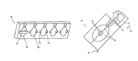
- FIG. 1 the schematic representation of a casting channel with a funnel-shaped subdivision device, in a perspective view
- FIG. 2 the schematic representation of a casting channel with a funnel-shaped subdivision device, in a top view
- FIG. 3 the schematic representation of a casting mold half, in a perspective view
- FIG. 4 the schematic representation of two parallel casting molds, disposed on a tilt axis, as casting mold halves each having a casting channel disposed on it, in a perspective view,
- FIG. 5 the schematic representation of two parallel casting molds, disposed on a tilt axis, as casting mold halves each having a casting channel disposed on it, in a top view,
- FIG. 6 the schematic representation of a casting mold composed of two casting mold halves, with a casting channel disposed on it, in the starting position, in a side view,
- FIG. 7 the schematic representation of a casting mold composed of two casting mold halves, with a casting channel disposed on it, in an intermediate position, in a side view, and
- FIG. 8 the schematic representation of a casting mold composed of two casting mold halves, with a casting channel disposed on it, in the end position, in a side view.
- FIG. 1 a casting channel 12 according to the invention, with a funnel-shaped subdivision device 20 and a casting pool 30 on one of the face sides 28 of the casting channel 12 , is shown in a perspective view.
- the casting channel 12 has five outlets 16 on the longitudinal side 14 facing the casting mold 10 , which outlets can each be connected, individually, with a separate mold cavity 18 of a casting mold, as shown in FIG. 3 .
- FIG. 3 Corresponding mold cavities 18 of a casting mold 10 , disposed next to one another and not standing in a flow connection with one another, are shown in FIG. 3 , whereby for the sake of simplicity, only one mold half of the casting mold 10 is shown.
- FIG. 3 therefore shows only one casting mold half 10 with a corresponding half mold cavity 18 .
- the casting channel 12 has a funnel-shaped subdivision device 20 , according to the invention, in the third of the casting channel 12 that faces the longitudinal side 14 .
- This subdivision device 20 is configured in such a manner that when the casting mold 10 , together with the casting channel 12 , is tilted, the volumes of the casting melt predetermined by the subdivision device flow through the outlets 16 .
- the volumes of the casting melt that flow through the outlet 16 are of the same size.
- the outlets 16 of the casting channel 12 in each instance, also have the same size.
- the subdivided volumes within the casting channel 12 generously stand in a flow connection in the region of the longitudinal side 22 that lies opposite the outlets 16 , whereby the flow connection in the transverse direction 24 takes up about two-thirds of the length of the casting channel 12 in the transverse direction 24 .
- such a subdivision is already sufficient to assign a predetermined volume of casting melt to the individual outlets 16 , and to fill the mold cavity 18 , in each instance, in uniform and homogeneous manner.
- the outlet 16 in each instance, is disposed at the low point 26 of the subdivision device 20 , in the end position of the casting mold 10 , in other words after tilting.
- the casting channel 12 has a casting pool 30 at one of its face sides 28 .
- the casting channel 12 shown in FIG. 2 essentially corresponds to the one shown in FIG. 1 , but is shown in a top view.
- FIG. 3 schematically represents a mold half of a casting mold 10 , having five mold cavities 18 that are separated from one another, whereby each mold cavity 18 , here also shown only by half, has supports 34 for a core 32 , whereby the core 32 is shown as an example in FIG. 3 , in the left mold cavity 18 .
- FIG. 4 shows, in perspective, an apparatus according to the invention, having two casting molds 10 or coquilles, disposed parallel, each of which has a casting channel 12 disposed on the casting mold 10 in its longitudinal direction. For the sake of a clearer illustration, however, only one casting mold half 10 of each casting mold 10 is shown.
- the two casting molds 10 together with the casting channels 12 , can be tilted only by way of a common tilt axis 8 , not shown here.
- the apparatus furthermore comprises a robot arm, not shown here, which has two casting ladles for parallel scooping and transport of the casting melt as well as for parallel filling of the casting melt into the casting channels 12 or into the casting pools 30 .
- a robot arm not shown here, which has two casting ladles for parallel scooping and transport of the casting melt as well as for parallel filling of the casting melt into the casting channels 12 or into the casting pools 30 .
- FIG. 5 shows the two casting molds 10 according to the invention, provided on a common tilt axis 8 , with the casting channel 12 according to the invention, according to FIG. 4 , disposed on them, in each instance, in a top view.
- FIGS. 6 to 8 show the casting mold 10 according to the invention, this time composed of two casting mold halves, with a casting channel 12 according to the invention, in three instantaneous views during casting.
- the casting mold 10 is first rotated or tilted into a starting position, on the side or into the horizontal, by 90°, so that a casting channel 12 assigned to the casting mold 10 and provided with at least two outlets 16 comes to lie horizontally next to the casting mold 10 , FIG. 6 . Then the flowable material is introduced into the casting channel 12 from above.
- FIG. 7 shows an intermediate position of the casting mold 10 .
- each mold cavity 18 has a core 32 that is formed from core-forming material, preferably sand, and an inorganic binder.
Landscapes
- Engineering & Computer Science (AREA)
- Mechanical Engineering (AREA)
- Molds, Cores, And Manufacturing Methods Thereof (AREA)
Applications Claiming Priority (4)
| Application Number | Priority Date | Filing Date | Title |
|---|---|---|---|
| DE102009031852 | 2009-07-03 | ||
| DE102009031852 | 2009-07-03 | ||
| DE102009031852.6 | 2009-07-03 | ||
| PCT/DE2010/000662 WO2011000343A1 (fr) | 2009-07-03 | 2010-06-14 | Dispositif, chenal de coulée et procédé de coulée par basculement de pièces en métal léger et pièces ainsi coulées |
Publications (2)
| Publication Number | Publication Date |
|---|---|
| US20120132321A1 US20120132321A1 (en) | 2012-05-31 |
| US8770264B2 true US8770264B2 (en) | 2014-07-08 |
Family
ID=42663777
Family Applications (1)
| Application Number | Title | Priority Date | Filing Date |
|---|---|---|---|
| US13/375,858 Expired - Fee Related US8770264B2 (en) | 2009-07-03 | 2010-06-14 | Device, gutter, method for tilt-casting components made of light metal, and components cast therewith |
Country Status (8)
| Country | Link |
|---|---|
| US (1) | US8770264B2 (fr) |
| EP (1) | EP2448698B1 (fr) |
| CN (1) | CN102470434B (fr) |
| DE (2) | DE102010023646A1 (fr) |
| ES (1) | ES2635690T3 (fr) |
| FR (1) | FR2947469A1 (fr) |
| IT (1) | IT1401098B1 (fr) |
| WO (1) | WO2011000343A1 (fr) |
Cited By (2)
| Publication number | Priority date | Publication date | Assignee | Title |
|---|---|---|---|---|
| US20160311017A1 (en) * | 2014-01-03 | 2016-10-27 | Fill Gesellschaft M.B.H. | Method for casting a cast part |
| US9895743B2 (en) | 2013-05-27 | 2018-02-20 | Fill Gesellschaft M.B.H. | Method and device for casting a cast part |
Families Citing this family (13)
| Publication number | Priority date | Publication date | Assignee | Title |
|---|---|---|---|---|
| DE102011052366B4 (de) * | 2011-08-02 | 2020-06-18 | Ks Huayu Alutech Gmbh | Verfahren und Vorrichtung zur Herstellung eines Leichtmetallbauteils durch Kippgießen |
| CN103182479B (zh) * | 2011-12-30 | 2015-01-28 | 上海爱仕达汽车零部件有限公司 | 一种真空泵箱体浇铸模具 |
| CN102806341B (zh) * | 2012-08-24 | 2014-04-02 | 中国南方航空工业(集团)有限公司 | 镁合金砂型铸造方法 |
| KR101485832B1 (ko) | 2013-04-23 | 2015-01-29 | 주식회사 엠티케이 | 중력을 이용한 알루미늄 주조용 장치 및 방법 |
| CN104525865B (zh) * | 2014-11-29 | 2017-07-18 | 西安航空动力控制科技有限公司 | 重力倾转铸造浇口盆 |
| CN104475716A (zh) * | 2014-12-15 | 2015-04-01 | 西南铝业(集团)有限责任公司 | 一种分配流槽 |
| DE102017100805A1 (de) * | 2017-01-17 | 2018-07-19 | Nemak, S.A.B. De C.V. | Gießform zum Gießen von komplex geformten Gussteilen und Verwendung einer solchen Gießform |
| DE102017114944B3 (de) * | 2017-07-05 | 2018-10-18 | Ksm Castings Group Gmbh | Anlage und Gießrinne zum Kippgießen von Bauteilen aus Leichtmetall |
| RU181962U1 (ru) * | 2017-12-15 | 2018-07-30 | Общество с ограниченной ответственностью "Объединенная Компания РУСАЛ Инженерно-технологический центр" | Устройство для получения лигатурных слитков методом наклонного литья |
| CN110711856A (zh) * | 2018-07-12 | 2020-01-21 | 新兴重工湖北三六一一机械有限公司 | 一种倾转浇注模具 |
| CN111496232B (zh) * | 2018-08-09 | 2021-07-02 | 临沂市金耐动力机械有限公司 | 一种金属加工用多位模具浇铸装置及其使用方法 |
| CN110961580B (zh) * | 2019-11-22 | 2021-09-21 | 中国航发西安动力控制科技有限公司 | 多流道浇注料斗 |
| CN114367634B (zh) * | 2021-10-29 | 2024-09-13 | 中国航发西安动力控制科技有限公司 | 铝合金铸件分区分段倾转铸造装置及其铸造方法 |
Citations (9)
| Publication number | Priority date | Publication date | Assignee | Title |
|---|---|---|---|---|
| DE2164755A1 (de) | 1971-12-27 | 1973-07-12 | Friedhelm Dr Ing Kahn | Giessverfahren mit erstarrungslenkung und einrichtung zur durchfuehrung des verfahrens |
| US4072180A (en) | 1975-02-22 | 1978-02-07 | W. H. Booth & Co. Limited | Process and mould for casting multiple articles |
| US4614217A (en) * | 1984-09-14 | 1986-09-30 | The Garrett Corporation | Method of assembling a horizontal shell mold casting system and the resulting system |
| US5704413A (en) | 1993-11-30 | 1998-01-06 | Honda Giken Kogyo Kabushiki Kaisha | Rotary-mold gravity casting process |
| US6929053B1 (en) | 2004-05-26 | 2005-08-16 | General Motors Corporation | Mold fill method and system |
| DE102004015649B3 (de) | 2004-03-31 | 2005-08-25 | Rautenbach-Guß Wernigerode GmbH | Verfahren und Vorrichtung zum Giessen von Bauteilen aus Leichtmetall nach dem Kippgiessprinzip |
| US20060175033A1 (en) | 2002-06-21 | 2006-08-10 | Philippe Meyer | Method for moulding light alloy cast parts, in particular cylinder blocks |
| DE102006058142A1 (de) | 2006-12-09 | 2008-06-12 | Volkswagen Ag | Verfahren und Vorrichtung zum Kippgießen von Bauteilen aus Leichtmetall |
| KR20090006502A (ko) | 2007-07-12 | 2009-01-15 | 대림기업 주식회사 | 중력주조공법에 의한 알루미늄 실린더 라이너의 제조장치및 그 방법 |
Family Cites Families (2)
| Publication number | Priority date | Publication date | Assignee | Title |
|---|---|---|---|---|
| CN1634673A (zh) * | 2003-12-25 | 2005-07-06 | 苏州工业园区明志铸造装备有限公司 | 倾转式重力铸造方法 |
| DE102006058145A1 (de) * | 2006-12-09 | 2008-06-12 | Ksm Castings Gmbh | Verfahren zum Verarbeiten, insbesondere Gießen, eines Materials, Gießform zur Durchführung des Verfahrens und nach dem Verfahren bzw. in der Gießform hergestellte Gegenstände |
-
2010
- 2010-06-14 DE DE102010023646A patent/DE102010023646A1/de not_active Withdrawn
- 2010-06-14 DE DE112010002827T patent/DE112010002827A5/de not_active Withdrawn
- 2010-06-14 CN CN201080029651.3A patent/CN102470434B/zh not_active Expired - Fee Related
- 2010-06-14 ES ES10736967.0T patent/ES2635690T3/es active Active
- 2010-06-14 EP EP10736967.0A patent/EP2448698B1/fr not_active Not-in-force
- 2010-06-14 WO PCT/DE2010/000662 patent/WO2011000343A1/fr active Application Filing
- 2010-06-14 US US13/375,858 patent/US8770264B2/en not_active Expired - Fee Related
- 2010-06-28 FR FR1055143A patent/FR2947469A1/fr not_active Withdrawn
- 2010-07-01 IT ITMI2010A001205A patent/IT1401098B1/it active
Patent Citations (9)
| Publication number | Priority date | Publication date | Assignee | Title |
|---|---|---|---|---|
| DE2164755A1 (de) | 1971-12-27 | 1973-07-12 | Friedhelm Dr Ing Kahn | Giessverfahren mit erstarrungslenkung und einrichtung zur durchfuehrung des verfahrens |
| US4072180A (en) | 1975-02-22 | 1978-02-07 | W. H. Booth & Co. Limited | Process and mould for casting multiple articles |
| US4614217A (en) * | 1984-09-14 | 1986-09-30 | The Garrett Corporation | Method of assembling a horizontal shell mold casting system and the resulting system |
| US5704413A (en) | 1993-11-30 | 1998-01-06 | Honda Giken Kogyo Kabushiki Kaisha | Rotary-mold gravity casting process |
| US20060175033A1 (en) | 2002-06-21 | 2006-08-10 | Philippe Meyer | Method for moulding light alloy cast parts, in particular cylinder blocks |
| DE102004015649B3 (de) | 2004-03-31 | 2005-08-25 | Rautenbach-Guß Wernigerode GmbH | Verfahren und Vorrichtung zum Giessen von Bauteilen aus Leichtmetall nach dem Kippgiessprinzip |
| US6929053B1 (en) | 2004-05-26 | 2005-08-16 | General Motors Corporation | Mold fill method and system |
| DE102006058142A1 (de) | 2006-12-09 | 2008-06-12 | Volkswagen Ag | Verfahren und Vorrichtung zum Kippgießen von Bauteilen aus Leichtmetall |
| KR20090006502A (ko) | 2007-07-12 | 2009-01-15 | 대림기업 주식회사 | 중력주조공법에 의한 알루미늄 실린더 라이너의 제조장치및 그 방법 |
Non-Patent Citations (3)
| Title |
|---|
| "Giessereilexikon" [Foundry Lexicon], 16th edition, 1994, p. 244 and p. 655. (Spec., p. 1). |
| International Search Report of PCT/DE2010/000662, date of mailing Oct. 14, 2010. |
| Kahn F: "Prozessleittechnik Und Qualitaettssicherung Beim Giessen Am Beispiel er Ne-Metallgussfertigung" Giesserei, Giesserei Verlag, Dussledorf, DE, vol. 80, No. 17, Sep. 6, 1993, pp. 579-584. (ISR). |
Cited By (3)
| Publication number | Priority date | Publication date | Assignee | Title |
|---|---|---|---|---|
| US9895743B2 (en) | 2013-05-27 | 2018-02-20 | Fill Gesellschaft M.B.H. | Method and device for casting a cast part |
| US20160311017A1 (en) * | 2014-01-03 | 2016-10-27 | Fill Gesellschaft M.B.H. | Method for casting a cast part |
| US9925586B2 (en) * | 2014-01-03 | 2018-03-27 | Fill Gesellschaft M.B.H. | Method for casting a cast part |
Also Published As
| Publication number | Publication date |
|---|---|
| FR2947469A1 (fr) | 2011-01-07 |
| CN102470434A (zh) | 2012-05-23 |
| CN102470434B (zh) | 2015-09-30 |
| ES2635690T3 (es) | 2017-10-04 |
| WO2011000343A1 (fr) | 2011-01-06 |
| EP2448698A1 (fr) | 2012-05-09 |
| DE112010002827A5 (de) | 2012-06-14 |
| ITMI20101205A1 (it) | 2011-01-04 |
| IT1401098B1 (it) | 2013-07-12 |
| EP2448698B1 (fr) | 2017-06-07 |
| US20120132321A1 (en) | 2012-05-31 |
| DE102010023646A1 (de) | 2011-01-05 |
Similar Documents
| Publication | Publication Date | Title |
|---|---|---|
| US8770264B2 (en) | Device, gutter, method for tilt-casting components made of light metal, and components cast therewith | |
| US8245759B2 (en) | Ladle for molten metal | |
| JP5044401B2 (ja) | 合金鋳造装置 | |
| CN107127304B (zh) | 一种汽车发动机缸体3d打印生产方法 | |
| WO2015055654A1 (fr) | Processus et machine de coulée pour couler des pièces métalliques | |
| US20190337047A1 (en) | Casting Mould for Casting Complex-Shaped Castings and Use of Such a Casting Mould | |
| US20150352631A1 (en) | Method and Casting Mould for the Manufacture of Cast Parts, in Particular Cylinder Blocks and Cylinder Heads, with a Functional Feeder Connection | |
| US9987681B2 (en) | Method of replacing a nozzle assembly for a molten metal holding and pouring box with dual pouring nozzles | |
| KR102041073B1 (ko) | 가스 배출기능을 구비하는 주조 몰드 시스템 | |
| US11007569B2 (en) | Method for tilt casting and tilt casting device | |
| KR101385008B1 (ko) | 주조 장치, 및 용융 물질을 주조 몰드로의 이송 방법 | |
| KR20090069807A (ko) | 금속 용탕의 유동도 측정관, 장비 및 방법 | |
| CN114012036B (zh) | 一种舱体振动试验用动圈铸件铸造方法 | |
| EP2581149A1 (fr) | Procédé permettant d'obtenir une pièce métallique | |
| RU2714788C1 (ru) | Способ изготовления литых прутковых заготовок из жаропрочных сплавов на никелевой основе | |
| JP4523144B2 (ja) | 金型の製造方法 | |
| US20240246142A1 (en) | System and method of making a cast reverse tilt-poured fuel cell cradle | |
| EP4357048A1 (fr) | Appareil et procédé pour couler des pièces métalliques | |
| JP2010214423A (ja) | 電磁ポンプ注湯式鋳型傾斜鋳造装置と方法 | |
| Saghi et al. | Flow behavior of molten metal in Aluminum LFC process | |
| CN117773013A (zh) | 用于制作燃料电池的倾斜浇注支架的系统和方法 | |
| KR20170059256A (ko) | 진동형 도가니받침대를 구비한 전기용해로 | |
| JP2019532820A (ja) | 金属ストランドの複数鋳造のための方法 | |
| GB2037633A (en) | Pouring tube for continuous casting | |
| UA48686A (uk) | Електронно-променева установка для відцентрового лиття |
Legal Events
| Date | Code | Title | Description |
|---|---|---|---|
| AS | Assignment |
Owner name: KSM CASTINGS GMBH, GERMANY Free format text: ASSIGNMENT OF ASSIGNORS INTEREST;ASSIGNORS:LANGE, UWE;OPPELT, HOLGER;STRUBE, ANDREAS;SIGNING DATES FROM 20111227 TO 20120104;REEL/FRAME:027605/0203 |
|
| AS | Assignment |
Owner name: KSM CASTINGS GROUP GMBH, GERMANY Free format text: MERGER;ASSIGNOR:KSM CASTINGS GMBH;REEL/FRAME:029155/0787 Effective date: 20120815 |
|
| STCF | Information on status: patent grant |
Free format text: PATENTED CASE |
|
| MAFP | Maintenance fee payment |
Free format text: PAYMENT OF MAINTENANCE FEE, 4TH YEAR, LARGE ENTITY (ORIGINAL EVENT CODE: M1551) Year of fee payment: 4 |
|
| FEPP | Fee payment procedure |
Free format text: MAINTENANCE FEE REMINDER MAILED (ORIGINAL EVENT CODE: REM.); ENTITY STATUS OF PATENT OWNER: LARGE ENTITY |
|
| LAPS | Lapse for failure to pay maintenance fees |
Free format text: PATENT EXPIRED FOR FAILURE TO PAY MAINTENANCE FEES (ORIGINAL EVENT CODE: EXP.); ENTITY STATUS OF PATENT OWNER: LARGE ENTITY |
|
| STCH | Information on status: patent discontinuation |
Free format text: PATENT EXPIRED DUE TO NONPAYMENT OF MAINTENANCE FEES UNDER 37 CFR 1.362 |
|
| FP | Lapsed due to failure to pay maintenance fee |
Effective date: 20220708 |