US8764281B2 - Anti-trip balance-spring for a timepiece escapement - Google Patents
Anti-trip balance-spring for a timepiece escapement Download PDFInfo
- Publication number
- US8764281B2 US8764281B2 US13/246,148 US201113246148A US8764281B2 US 8764281 B2 US8764281 B2 US 8764281B2 US 201113246148 A US201113246148 A US 201113246148A US 8764281 B2 US8764281 B2 US 8764281B2
- Authority
- US
- United States
- Prior art keywords
- balance
- spring
- equilibrium
- coils
- segments
- Prior art date
- Legal status (The legal status is an assumption and is not a legal conclusion. Google has not performed a legal analysis and makes no representation as to the accuracy of the status listed.)
- Active, expires
Links
Images


Classifications
-
- G—PHYSICS
- G04—HOROLOGY
- G04B—MECHANICALLY-DRIVEN CLOCKS OR WATCHES; MECHANICAL PARTS OF CLOCKS OR WATCHES IN GENERAL; TIME PIECES USING THE POSITION OF THE SUN, MOON OR STARS
- G04B17/00—Mechanisms for stabilising frequency
- G04B17/04—Oscillators acting by spring tension
- G04B17/06—Oscillators with hairsprings, e.g. balance
- G04B17/066—Manufacture of the spiral spring
-
- G—PHYSICS
- G04—HOROLOGY
- G04B—MECHANICALLY-DRIVEN CLOCKS OR WATCHES; MECHANICAL PARTS OF CLOCKS OR WATCHES IN GENERAL; TIME PIECES USING THE POSITION OF THE SUN, MOON OR STARS
- G04B17/00—Mechanisms for stabilising frequency
- G04B17/20—Compensation of mechanisms for stabilising frequency
- G04B17/26—Compensation of mechanisms for stabilising frequency for the effect of variations of the impulses
-
- Y—GENERAL TAGGING OF NEW TECHNOLOGICAL DEVELOPMENTS; GENERAL TAGGING OF CROSS-SECTIONAL TECHNOLOGIES SPANNING OVER SEVERAL SECTIONS OF THE IPC; TECHNICAL SUBJECTS COVERED BY FORMER USPC CROSS-REFERENCE ART COLLECTIONS [XRACs] AND DIGESTS
- Y10—TECHNICAL SUBJECTS COVERED BY FORMER USPC
- Y10T—TECHNICAL SUBJECTS COVERED BY FORMER US CLASSIFICATION
- Y10T29/00—Metal working
- Y10T29/49—Method of mechanical manufacture
- Y10T29/49609—Spring making
Definitions
- the present invention relates to an anti-trip balance-spring for a detent type timepiece escapement which has no stop member.
- Detent escapements are notably used in precision timepieces, since they disturb the isochronism of the oscillator less than Swiss lever escapements.
- This type of escapement reference may be made to chapter 6.7.1 of the work entitled “Théorie de l′horlogerie” ( Theory of Horology ). We will merely mention here the principle of tripping to which it is subject.
- the sprung balance oscillator oscillates between two extreme positions, a “high” position and a “low” position.
- Each of the oscillations includes a “rising” vibration, during which it changes from the low position to the high position, and a “falling” vibration during which it changes from the high position to the low position.
- the escape wheel delivers one impulse per oscillation to the sprung-balance oscillator in the rising vibration, in an “equilibrium” position, approximately half way between the high position and the low position.
- the sprung balance does not receive any impulses. It should be noted that it is unimportant whether the rising and falling vibrations are associated with the contraction or radial extension of the balance-spring.
- each vibration namely the angular displacement of the oscillator from the position of equilibrium to the high or low position
- the amplitude of each vibration is typically 330°.
- the sprung balance may receive an excessive amount of energy causing the amplitude to exceed this value, and even exceed 360°, the limit value beyond which the sprung balance receives an additional impulse.
- the rising vibration may then count two impulses, whereas the falling vibration may count one.
- the escape wheel which normally makes one step per oscillation, then makes two or even three steps during the same oscillation. This racing of the sprung balance, which is self-maintained, is called “tripping”. It impairs the precision of the movement, since each additional step taken by the escape wheel makes the time measurement fast by a duration that is inversely proportional to the oscillation frequency of the sprung balance.
- One of these mechanisms includes a pinion rotating integrally with the sprung balance. Said pinion meshes with a pivotably mounted, toothed sector, fitted with two end spokes able to abut against a fixed stop if the balance is driven beyond a determined angle of rotation.
- This device is efficient in preventing the oscillator from racing, in both directions of rotation. However, it generates losses in the gear between the pinion and the toothed sector, which disturb the isochronism of the sprung balance.
- Another mechanism disclosed in EP Patent Application No.
- 1 645 918 includes an arm, mounted radially on the last coil of the balance-spring, which is inserted between a finger integral with the balance and two columns mounted on a balance bridge, when the sprung balance exceeds a certain angular and radial extension.
- This device is difficult to implement, essentially because of the extreme precision required for the assembly thereof.
- the present invention proposes a simple and robust alternative to existing anti-trip devices. It concerns more specifically an anti-trip balance-spring for a timepiece escapement, intended to oscillate between two extreme positions, passing through a position of equilibrium and including a plurality of coils. According to the invention, it also includes means for locking at least two consecutive coils when the amplitude of rotation from the point of equilibrium to at least one of the end positions, reaches a determined angle ⁇ .
- this means includes transverse segments integral with consecutive coils, angularly shifted to abut against each other when the amplitude of rotation of the balance-spring according to the invention reaches a determined angle ⁇ , from said point of equilibrium to at least one of the end positions thereof.
- the present invention also concerns a timepiece escapement fitted with an anti-trip balance-spring of this type.
- FIGS. 1 and 2 are top views of a first embodiment of an anti-trip balance-spring according to the invention, respectively in the position of equilibrium and in a locking position,
- FIG. 3 illustrates a variant of the first embodiment of this type of balance-spring
- FIG. 4 shows an advantageous variant of the first embodiment of an anti-trip balance-spring according to the invention, in a locking position
- FIG. 5 is a view of a detail of the balance-spring shown in FIG. 4 ;
- FIGS. 6 and 7 are top views of second and third embodiments of an anti-trip balance-spring according to the invention, configured to form a lock during contraction.
- FIGS. 8 and 9 illustrate the same second and third embodiments of the anti-trip balance-spring according to the invention, this time configured to form a lock during extension, and
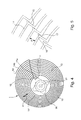
- FIG. 10 shows an anti-trip balance-spring according to the invention, combining the features of embodiments 7 and 9.
- the anti-trip balance-spring shown in the position of equilibrium in FIGS. 1 , 3 , 6 , 7 , 8 , 9 and 10 with the general reference 1 is generally formed by a strip 10 wound in a spiral on itself, so as to have angular elasticity.
- the central end 11 of strip 10 is pinned up in a known manner to a collet 20 driven onto a balance staff 21 , while the peripheral end 12 thereof is intended to be secured to a balance cock, which is not shown.
- balance-spring 1 includes a plurality of coils 13 , typically between 10 and 15 , having a pitch p between them at equilibrium.
- balance-spring 1 further includes a plurality of transverse, segments 15 , 15 ′, 15 ′′ a , 15 ′′ b , 15 ′′ c integral with successive coils 13 and angularly arranged to abut on each other, when the amplitude of rotation of balance-spring 1 exceeds a determined angle ⁇ , comprised between 300° and 360°, from the position of equilibrium to one of the end positions thereof.
- balance-spring 1 is formed, from the central end 11 , of a first spiral portion 14 a for connection to collet 20 , then a succession of spiral portions 14 of pitch p, connected to each other by transverse segments 15 of length l and finally, a last spiral portion 14 b for connection to a balance cock.
- segments 15 extend radially, but in a variant, they may be slightly inclined relative to the radial orientation.
- the initial radius of a spiral portion 14 is equal to the final radius of a preceding portion 14 increased by the length l of one segment 15 .
- Successive transverse segments 15 are arranged angularly to abut against each other when the amplitude of the vibration associated with the balance-spring 1 contraction reaches a determined value ⁇ comprised between 300° and 360°.
- balance-spring 1 in the position of equilibrium thereof, are linked by geometrical relationships which are explained below.
- the number of coils 13 of balance-spring 1 from the central end 11 to the peripheral end 12 is referenced N
- the radius of the nth coil 13 is referenced R n
- the radii respectively of the first and last coil 13 are referenced R 1 and R N .
- the angular shift from the equilibrium position, relative to the radially aligned position, between the transverse segments 15 respectively associated with the nth and n+1th coils 13 is referenced ⁇ n
- the angular sector of the nth spiral portion 14 is referenced ⁇ n .
- ⁇ n ⁇ N ⁇ R n R N - R 1
- the angular sector ⁇ n of an nth spiral portion 14 is the complement of the angular shift ⁇ n between the radial segments 15 respectively associated with the nth and n+1th coils 13 . It thus obeys the following relation:
- ⁇ n 360 - ⁇ N ⁇ R n R N - R 1
- transverse segments 15 abut against each other beyond a determined rotation angle LP in contraction, as shown in FIG. 2 .
- Coils 13 are thus locked in rotation relative to each other and balance-spring 1 has no more, or virtually no more, angular elasticity.
- the movement of rotation of said balance-spring is abruptly locked. Tripping is thus prevented in the vibration associated with the contraction of balance-spring 1 .
- This vibration will preferably be the rising vibration, since tripping occurs more frequently during that vibration.
- balance-spring 1 is formed, at a minimum, of a first spiral portion 14 a of any angular sector, a second spiral portion 14 of angular sector
- balance-spring 1 may include two, three and up to N′ spiral portions 14 , and respectively three, four and up to N′+1 transverse segments 15 , where N′ is a function of the number N of coils 13 and angle ⁇ .
- the braking of balance-spring 1 increases with the number of spiral portions 14 and transverse segments 15 until total locking of the balance-spring when the number of spiral portions 14 takes the maximum value N′.
- segments 15 extend radially slightly beyond the two spiral portions 14 which they connect, and include two fingers 16 and 17 at the ends thereof, extending angularly towards the exterior of the spiral portions 14 which said segments connect.
- fingers 16 and 17 fit into each other when segments 15 are abutting.
- Segments 15 are then radially locked in relation to each other, which, in addition to angular rigidity, gives balance-spring 1 radial rigidity, when the determined amplitude is reached.
- the locking of balance-spring 1 is ensured even in the event of violent shocks, since the radial elasticity does not compensate, in this case, for the angular rigidity.
- FIGS. 6 and 7 respectively show second and third embodiments of balance-spring 1 according to the invention.
- Balance spring 1 illustrated in FIGS. 6 and 7 differs from the embodiment described with reference to FIGS. 1 and 2 in that it is formed of a single spiral portion 14 , from the central end 11 , to the peripheral end 12 , which is integral with transverse segments 15 ′ and 15 ′′ a and 15 ′′ b.
- the length of transverse segments 15 ′ is greater than or equal to p and less than or equal to 2 p, and said segments are secured via the middle thereof to the single spiral portion 14 .
- the segments extend substantially radially, but in a variant, may be slightly inclined relative to the radial orientation. In such case, the inclination must be selected so that it does not prevent the return of balance-spring 1 to equilibrium, if the determined angle ⁇ is exceeded.
- the angular shift ⁇ n between the transverse segments 15 ′ respectively associated with the nth and n+1th coils 13 has a value
- balance-spring 1 When the rotation of balance-spring 1 according to the invention exceeds the critical value during the amplitude associated with contraction, segments 15 ′ are aligned radially and abut against each other. Balance spring 1 is thus locked in rotation.
- balance-spring 1 has first transverse segments 15 ′′ a and second transverse segments 15 ′′ b , secured to the single spiral portion 14 via one of the ends thereof.
- the first transverse segments 15 ′′ a point towards the exterior of balance-spring 1
- the second transverse segments 15 ′′ b point towards the interior of balance-spring 1 .
- the length l of both is greater than or equal to p/2, and less than p.
- Each coil 13 has a transverse segment 15 ′′ a and a transverse segment 15 ′′ b .
- the first coil 13 from the central end 11 includes a single transverse segment 15 ′′ a oriented towards the exterior, whereas the last has only one 15 ′′ b oriented towards the interior.
- the transverse segments 15 ′′ a are aligned radially along a radius of balance-spring 1 and transverse segments 15 ′′ b are shifted relative to segments 15 ′′ a by an angle ⁇ n .
- the shift ⁇ n between a segment 15 ′′ a associated with an nth coil 13 and a segment 15 ′′ b associated with an n+1th coil 13 has a value
- segments 15 ′ and 15 ′′ a , 15 ′′ b of balance-spring 1 described with reference to FIGS. 6 and 7 include fingers 16 and 17 extending angularly and intended to fit into each other to give balance-spring 1 radial rigidity in the angular locking position. This effect has already been described with reference to FIGS. 3 and 4 .
- FIGS. 8 and 9 illustrate a particular configuration of the balance springs 1 shown in FIGS. 6 and 7 which allow this effect.
- the balance-spring 1 shown in FIG. 8 differs from the balance-spring 1 described with reference to FIG. 6 , in that the transverse segments 15 ′ are arranged for locking said spring when the amplitude of rotation thereof exceeds a critical value ⁇ in extension and not in contraction.
- the operating principle is the same, but the rules of construction are different.
- the angular shift from equilibrium ⁇ n between two transverse segments 15 ′ respectively associated with the n and n+1th coils 13 has a value
- the pitch p of a balance-spring 1 increases, when it extends radially, by a value that depends upon the vibration amplitude and the number N of coils 13 .
- the length l of transverse segments 15 ′ must then be such that they contact each other during the vibration associated with extension.
- the following relation is given: l ⁇ 1.6p
- each segment 15 ′ abuts against a consecutive segment 15 ′ when the rotation amplitude of balance-spring 1 reaches a determined angle ⁇ in extension, and the rotation of balance-spring 1 is thus locked.
- the balance-spring 1 illustrated in FIG. 9 differs from the balance-spring 1 described with reference to FIG. 6 in that it includes segments 15 ′′ a and 15 ′′ c provided for locking the rotation thereof in extension and not in contraction.
- the transverse segments 15 ′′ a are aligned along a radius of balance-spring 1 .
- segments 15 ′′ c point towards the interior of balance-spring 1 , but they differ therefrom in their position relative to segments 15 ′′ a .
- the value of the shift ⁇ n between an nth coil 13 and a segment 15 ′′ c associated with an n+1th coil 13 is
- segments 15 ′′ a and 15 ′′ c are typically equal to 0.8 p.
- FIG. 10 showing a balance-spring 1 intended to be locked in extension and in contraction when the rotation amplitude thereof reaches a determined value ⁇ .
- Said balance-spring 1 combines the features of the balance-spring 1 shown in FIG. 7 and the balance-spring 1 shown in FIG. 9 . It includes first segments 15 ′′ a , second segments 15 ′′ b and third segments 15 ′′ c , positioned in the manner described above in relation to each other.
- the transverse segments 15 ′′ a are thus aligned along a radius of balance-spring 1 and transverse segments 15 ′′ b et 15 ′′ c are shifted either side of segments 15 ′′ a by an angle ⁇ n equal to
- Balance spring 1 is fabricated in a material with elastic properties.
- silicon will be chosen to fabricate the balance-spring, using a photolithographic method well known to those skilled in the art.
- a metal balance-spring could be chosen, for example nickel, or a nickel alloy and/or obtained by via a LIGA type physicochemical deposition method.
Landscapes
- Physics & Mathematics (AREA)
- General Physics & Mathematics (AREA)
- Engineering & Computer Science (AREA)
- Manufacturing & Machinery (AREA)
- Springs (AREA)
- Harvester Elements (AREA)
Abstract
Description
2p>l≧p
and a
whereas the angular sector Φn separating them is
When the rotation of balance-
and the angular sector Φn separating them is equal to
When the rotation of balance-
but the angular sector Φn separating them is equal to
Moreover, the pitch p of a balance-
l¢1.6p
but the angular segment Φn separating them is equal to
The length l of
When the rotation amplitude of the balance-spring thus configured reaches determined angle Ψ, in contraction or extension,
Claims (13)
Applications Claiming Priority (3)
| Application Number | Priority Date | Filing Date | Title |
|---|---|---|---|
| EP10181111.5 | 2010-09-28 | ||
| EP10181111.5A EP2434353B1 (en) | 2010-09-28 | 2010-09-28 | Anti-tripping hairspring for timepiece escapement |
| EP10181111 | 2010-09-28 |
Publications (2)
| Publication Number | Publication Date |
|---|---|
| US20120075963A1 US20120075963A1 (en) | 2012-03-29 |
| US8764281B2 true US8764281B2 (en) | 2014-07-01 |
Family
ID=43643540
Family Applications (1)
| Application Number | Title | Priority Date | Filing Date |
|---|---|---|---|
| US13/246,148 Active 2032-12-20 US8764281B2 (en) | 2010-09-28 | 2011-09-27 | Anti-trip balance-spring for a timepiece escapement |
Country Status (4)
| Country | Link |
|---|---|
| US (1) | US8764281B2 (en) |
| EP (1) | EP2434353B1 (en) |
| JP (1) | JP5372092B2 (en) |
| CN (1) | CN102419541B (en) |
Cited By (3)
| Publication number | Priority date | Publication date | Assignee | Title |
|---|---|---|---|---|
| US9268307B2 (en) * | 2013-12-16 | 2016-02-23 | Eta Sa Manufacture Horlogere Suisse | Polygonal balance spring for a resonator for a timepiece |
| US20160299470A1 (en) * | 2013-12-16 | 2016-10-13 | Eta Sa Manufacture Horlogère Suisse | Balance spring with coil spacer device |
| US11474479B2 (en) * | 2019-02-15 | 2022-10-18 | Seiko Instruments Inc. | Hairspring, balance with hairspring, timepiece movement, and timepiece |
Families Citing this family (10)
| Publication number | Priority date | Publication date | Assignee | Title |
|---|---|---|---|---|
| US8562206B2 (en) * | 2010-07-12 | 2013-10-22 | Rolex S.A. | Hairspring for timepiece hairspring-balance oscillator, and method of manufacture thereof |
| EP2690506B1 (en) | 2012-07-25 | 2015-01-14 | Nivarox-FAR S.A. | Anti-tripping clock hairspring |
| EP2690508B1 (en) | 2012-07-26 | 2015-02-25 | Nivarox-FAR S.A. | Horological hairspring |
| EP2690507B1 (en) | 2012-07-26 | 2014-12-31 | Nivarox-FAR S.A. | Holorological hairspring |
| EP2804054B1 (en) * | 2013-05-17 | 2020-09-23 | ETA SA Manufacture Horlogère Suisse | Anti-adhesion device of a spiral on a bridge |
| EP2908183B1 (en) * | 2014-02-14 | 2018-04-18 | ETA SA Manufacture Horlogère Suisse | Clock hairspring |
| EP2908187B1 (en) | 2014-02-17 | 2016-10-19 | The Swatch Group Research and Development Ltd. | Adjustment of a clock piece resonator by changing the active length of a hairspring |
| EP3159748B1 (en) * | 2015-10-22 | 2018-12-12 | ETA SA Manufacture Horlogère Suisse | Compact hairspring with variable cross-section |
| WO2019103977A1 (en) * | 2017-11-21 | 2019-05-31 | Firehouse Horology, Inc. | Geometries for hairsprings for mechanical watches enabled by nanofabrication |
| CN110160339B (en) * | 2018-02-05 | 2020-10-23 | 嘉兴诺丁汉工业设计有限公司 | Industrial material is with mixing drying equipment based on sector gear disturbance principle |
Citations (3)
| Publication number | Priority date | Publication date | Assignee | Title |
|---|---|---|---|---|
| US3696687A (en) * | 1971-03-25 | 1972-10-10 | Ametek Inc | Plastic hairspring |
| EP1431844A1 (en) | 2002-12-19 | 2004-06-23 | SFT Services SA | Assembly for the regulating organ of a watch movement |
| US20060072376A1 (en) | 2004-10-05 | 2006-04-06 | Montres Breguet Sa | Antitripping device for watch-escapement |
Family Cites Families (5)
| Publication number | Priority date | Publication date | Assignee | Title |
|---|---|---|---|---|
| IT985551B (en) * | 1971-09-27 | 1974-12-10 | Golay Bernard Sa | TOGETHER INCLUDING A SPIRAL INTENDED TO BE APPLIED TO AN OSCILLATING ORGAN SUBJECTED TO THE ACTION OF MEANS THAT SYNCHRONIZE THE FREQUENCY WITH THAT OF A PILOT FREQUENCY |
| EP1445670A1 (en) * | 2003-02-06 | 2004-08-11 | ETA SA Manufacture Horlogère Suisse | Balance-spring resonator spiral and its method of fabrication |
| EP1473604B1 (en) * | 2003-04-29 | 2010-06-23 | Patek Philippe SA Genève | Balance and flat hairspring regulator for a watch movement |
| DE602005013416D1 (en) | 2005-12-20 | 2009-04-30 | Montres Breguet Sa | Device for monitoring the good gear of a clock oscillator |
| EP2151722B8 (en) * | 2008-07-29 | 2021-03-31 | Rolex Sa | Hairspring for balance-spring resonator |
-
2010
- 2010-09-28 EP EP10181111.5A patent/EP2434353B1/en active Active
-
2011
- 2011-09-20 JP JP2011204173A patent/JP5372092B2/en active Active
- 2011-09-27 US US13/246,148 patent/US8764281B2/en active Active
- 2011-09-27 CN CN2011102950664A patent/CN102419541B/en active Active
Patent Citations (4)
| Publication number | Priority date | Publication date | Assignee | Title |
|---|---|---|---|---|
| US3696687A (en) * | 1971-03-25 | 1972-10-10 | Ametek Inc | Plastic hairspring |
| EP1431844A1 (en) | 2002-12-19 | 2004-06-23 | SFT Services SA | Assembly for the regulating organ of a watch movement |
| US20060072376A1 (en) | 2004-10-05 | 2006-04-06 | Montres Breguet Sa | Antitripping device for watch-escapement |
| EP1645918A1 (en) | 2004-10-05 | 2006-04-12 | Montres Breguet S.A. | Anti-tripping device for timepiece escapement |
Non-Patent Citations (2)
| Title |
|---|
| Charles-André Reymondin, et al., "Theory of Horology", Chapter 6.7 Some other types of escapements, 6.7.1 Detent escapement, Sep. 1999, 1 page. |
| European Search Report issued Mar. 10, 2011, in French 10 18 1111, filed Sep. 28, 2010 (with English Translation of Category of Cited Documents). |
Cited By (4)
| Publication number | Priority date | Publication date | Assignee | Title |
|---|---|---|---|---|
| US9268307B2 (en) * | 2013-12-16 | 2016-02-23 | Eta Sa Manufacture Horlogere Suisse | Polygonal balance spring for a resonator for a timepiece |
| US20160299470A1 (en) * | 2013-12-16 | 2016-10-13 | Eta Sa Manufacture Horlogère Suisse | Balance spring with coil spacer device |
| US9645549B2 (en) * | 2013-12-16 | 2017-05-09 | Eta Sa Manufacture Horlogere Suisse | Balance spring with coil spacer device |
| US11474479B2 (en) * | 2019-02-15 | 2022-10-18 | Seiko Instruments Inc. | Hairspring, balance with hairspring, timepiece movement, and timepiece |
Also Published As
| Publication number | Publication date |
|---|---|
| CN102419541A (en) | 2012-04-18 |
| EP2434353A1 (en) | 2012-03-28 |
| JP2012073248A (en) | 2012-04-12 |
| CN102419541B (en) | 2013-07-31 |
| US20120075963A1 (en) | 2012-03-29 |
| EP2434353B1 (en) | 2018-01-10 |
| HK1169494A1 (en) | 2013-01-25 |
| JP5372092B2 (en) | 2013-12-18 |
Similar Documents
| Publication | Publication Date | Title |
|---|---|---|
| US8764281B2 (en) | Anti-trip balance-spring for a timepiece escapement | |
| US9465362B2 (en) | Oscillator with a detent escapement | |
| US20080008051A1 (en) | Mobile micromechanical element with shock controlled rotation | |
| JP6695889B2 (en) | Monolithic watch regulators, watch movements and watches with such watch regulators | |
| US9016934B2 (en) | Anti-trip balance spring for a timepiece | |
| TWI713564B (en) | Oscillator with rotating detent | |
| JP5351238B2 (en) | Tooth skip prevention device for escapement mechanism | |
| HK1253383A1 (en) | Mechanism for adjusting an average speed in a clock movement and clock movement | |
| JP2023178243A (en) | Timer adjustment member provided with index assembly system | |
| US7527424B2 (en) | Anti-trip device for timepiece escapement | |
| CN108375891A (en) | Temperature compensating type hair-spring balance, movement and clock and watch | |
| HK1169494B (en) | Anti-trip balance-spring for a timepiece escapement | |
| CN223308552U (en) | External pile holder, speed regulating mechanism for timepiece movement and timepiece movement | |
| CH703833A2 (en) | Anti-tripping hairspring for detent type timepiece escapement, has blocking units for blocking consecutive spiral-turns when rotation amplitude of hairspring from balance position to extreme position reaches determined angle | |
| HK40096164A (en) | Timepiece regulating member provided with a precision index-assembly system | |
| HK40120869A (en) | Timepiece regulating member comprising an improved index system | |
| CN120178640A (en) | Pin holder for a timepiece regulating member provided with a device for regulating the rate and/or isochronism | |
| HK40096165A (en) | Timepiece regulating member comprising an index-assembly system provided with locking means | |
| HK1194490B (en) | Anti-trip balance spring for a timepiece | |
| HK40014962A (en) | Timepiece resonator mechanism, timepiece oscillator mechanism, timepiece movement and watch | |
| HK40014962B (en) | Timepiece resonator mechanism, timepiece oscillator mechanism, timepiece movement and watch | |
| HK1104621B (en) | Anti-trip device for timepiece escapement | |
| HK1208739B (en) | Clock movement having a balance and a hairspring | |
| HK1228522A1 (en) | Oscillator with a detent escapement | |
| HK1194492B (en) | Timepiece balance spring |
Legal Events
| Date | Code | Title | Description |
|---|---|---|---|
| AS | Assignment |
Owner name: MONTRES BREGUET SA, SWITZERLAND Free format text: ASSIGNMENT OF ASSIGNORS INTEREST;ASSIGNOR:ZAUGG, ALAIN;REEL/FRAME:026975/0416 Effective date: 20110810 |
|
| STCF | Information on status: patent grant |
Free format text: PATENTED CASE |
|
| MAFP | Maintenance fee payment |
Free format text: PAYMENT OF MAINTENANCE FEE, 4TH YEAR, LARGE ENTITY (ORIGINAL EVENT CODE: M1551) Year of fee payment: 4 |
|
| MAFP | Maintenance fee payment |
Free format text: PAYMENT OF MAINTENANCE FEE, 8TH YEAR, LARGE ENTITY (ORIGINAL EVENT CODE: M1552); ENTITY STATUS OF PATENT OWNER: LARGE ENTITY Year of fee payment: 8 |
|
| MAFP | Maintenance fee payment |
Free format text: PAYMENT OF MAINTENANCE FEE, 12TH YEAR, LARGE ENTITY (ORIGINAL EVENT CODE: M1553); ENTITY STATUS OF PATENT OWNER: LARGE ENTITY Year of fee payment: 12 |