US8742704B2 - AC motor control device and AC motor driving system - Google Patents
AC motor control device and AC motor driving system Download PDFInfo
- Publication number
- US8742704B2 US8742704B2 US13/202,667 US201013202667A US8742704B2 US 8742704 B2 US8742704 B2 US 8742704B2 US 201013202667 A US201013202667 A US 201013202667A US 8742704 B2 US8742704 B2 US 8742704B2
- Authority
- US
- United States
- Prior art keywords
- motor
- axis
- axes
- current
- state variable
- Prior art date
- Legal status (The legal status is an assumption and is not a legal conclusion. Google has not performed a legal analysis and makes no representation as to the accuracy of the status listed.)
- Expired - Fee Related, expires
Links
- 230000004907 flux Effects 0.000 claims abstract description 154
- 238000004364 calculation method Methods 0.000 claims description 34
- 238000012886 linear function Methods 0.000 claims description 29
- 230000001360 synchronised effect Effects 0.000 claims description 11
- 230000014509 gene expression Effects 0.000 claims description 8
- 238000013459 approach Methods 0.000 claims description 2
- 238000000034 method Methods 0.000 description 27
- 238000010586 diagram Methods 0.000 description 22
- 238000004458 analytical method Methods 0.000 description 13
- 230000010349 pulsation Effects 0.000 description 12
- 238000001514 detection method Methods 0.000 description 11
- 230000004044 response Effects 0.000 description 6
- 238000006243 chemical reaction Methods 0.000 description 4
- 238000005516 engineering process Methods 0.000 description 3
- 101100432968 Mus musculus Yrdc gene Proteins 0.000 description 2
- 239000003990 capacitor Substances 0.000 description 2
- 230000007423 decrease Effects 0.000 description 2
- 230000003247 decreasing effect Effects 0.000 description 2
- 238000009499 grossing Methods 0.000 description 2
- 238000004891 communication Methods 0.000 description 1
- 230000000694 effects Effects 0.000 description 1
- 230000006872 improvement Effects 0.000 description 1
- 230000006698 induction Effects 0.000 description 1
- 230000003993 interaction Effects 0.000 description 1
- 230000008569 process Effects 0.000 description 1
- 238000012887 quadratic function Methods 0.000 description 1
- 229920006395 saturated elastomer Polymers 0.000 description 1
- 238000004804 winding Methods 0.000 description 1
- 229910000859 α-Fe Inorganic materials 0.000 description 1
Images
Classifications
-
- H—ELECTRICITY
- H02—GENERATION; CONVERSION OR DISTRIBUTION OF ELECTRIC POWER
- H02P—CONTROL OR REGULATION OF ELECTRIC MOTORS, ELECTRIC GENERATORS OR DYNAMO-ELECTRIC CONVERTERS; CONTROLLING TRANSFORMERS, REACTORS OR CHOKE COILS
- H02P21/00—Arrangements or methods for the control of electric machines by vector control, e.g. by control of field orientation
- H02P21/14—Estimation or adaptation of machine parameters, e.g. flux, current or voltage
- H02P21/141—Flux estimation
-
- H—ELECTRICITY
- H02—GENERATION; CONVERSION OR DISTRIBUTION OF ELECTRIC POWER
- H02P—CONTROL OR REGULATION OF ELECTRIC MOTORS, ELECTRIC GENERATORS OR DYNAMO-ELECTRIC CONVERTERS; CONTROLLING TRANSFORMERS, REACTORS OR CHOKE COILS
- H02P21/00—Arrangements or methods for the control of electric machines by vector control, e.g. by control of field orientation
- H02P21/14—Estimation or adaptation of machine parameters, e.g. flux, current or voltage
- H02P21/18—Estimation of position or speed
-
- H—ELECTRICITY
- H02—GENERATION; CONVERSION OR DISTRIBUTION OF ELECTRIC POWER
- H02P—CONTROL OR REGULATION OF ELECTRIC MOTORS, ELECTRIC GENERATORS OR DYNAMO-ELECTRIC CONVERTERS; CONTROLLING TRANSFORMERS, REACTORS OR CHOKE COILS
- H02P21/00—Arrangements or methods for the control of electric machines by vector control, e.g. by control of field orientation
- H02P21/24—Vector control not involving the use of rotor position or rotor speed sensors
- H02P21/26—Rotor flux based control
Definitions
- the present invention relates to an AC motor control device and particularly to setting a state quantity of an AC motor.
- AC motors particularly, permanent magnet synchronous motors have an expanded use in, for example, a home electric appliance field, an industrial use, and motor vehicle because of their small size and high efficiency.
- products have increased in the number which has a sinusoidal-wave-conducting type of driving method in place of products having the square-wave-conducting type of driving method.
- controllers have been increased in the number which are used for, for example, a rotor position estimation in the position-sensor-less control and a high accuracy torque control and require input of motor electric constant setting values such as resistance, inductance, and an induced voltage constant. Accordingly, if the motor electric constants are not accurately determined and inputted, this will largely influences the control performance.
- inductance largely influences magnetic saturation because a magnetic nonlinearity of a core largely influences the inductance.
- Patent document 1 discloses a technology in which the electric constant setting value of the AC motor is varied in accordance with current. This technology provides an improvement in a torque accuracy by that the controller has a nonlinear function of a relation between a magnetic flux and a current of a synchronous motor (hereinbelow will be referred to as prior art 1).
- patent document 2 discloses a technology for a control with a high accuracy and a high response by directly tabling the relation between the magnetic flux and the current with interlinkage flux in place of the inductance which is an electric constant (hereinbelow will be referred to as prior art 2).
- Prior art 1 describes that there is interference magnetic flux between axes such as occurrence of a q-axis magnetic flux by a d-axis current and refers to the relation as a nonlinear magnetic flux function. However, there is no specific description about the function, but a method of using table data.
- Prior art 2 shows an approximate equation of the interlinkage flux in which an interaction between the d-axis and the q-axis is considered with the current being used as a parameter.
- Prior art 2 mainly describes the method of using a two-dimensional table data of the interlinkage flux.
- the indicated approximate equation of flux interlinkage is a quadratic function of the current, it is difficult to obtain an inverse function thereof.
- the present invention has been developed in consideration of the above-described points and aims to provide an AC motor control device capable of setting a non-linear state quantity of the AC motor varying in accordance with a driving state of the AC motor with a high accuracy and using the setting for motor control.
- the aim can be achieved by providing a state quantity calculating part for calculating a state quantity corresponding to a coil interlinkage flux which is an internal quantity of the motor and a setting value of the coil interlinkage flux defined on either of two axes, i.e., the d-axis and q-axis, which are orthogonal is calculated with each other on a rotary coordinate system with a function formula using a current defined with a current which is a state variation defined on the same axis and a current defined on the other axis.
- the present invention provides an AC motor control device, including an inverter configured to apply a pulse width modulation voltage to an AC motor to drive the AC motor, means for detecting a current in the AC motor, and a controller configured to adjust the pulse width modulation voltage outputted by the inverter to drive the AC motor, characterized in that:
- the controller includes a state quantity calculating unit configured to calculate a state quantity of the motor
- the state quantity calculating unit calculates a setting value of the state quantity defined on either one of two axes orthogonal to each other in a rotary coordinate system of the motor using at least one of state variables defined on the same one of the axes and the other one of the axes and uses the calculated state quantity for driving control of the AC motor.
- the AC motor control device is characterized in that calculation of the state quantity setting values by the state variables defined on the same one of the axes and the other one of the axes is performed with a function formula using a constant featuring influence of the state variable on the state quantity, wherein the state variable is a parameter.
- the AC motor control device is characterized in that the function formula is a fractional expression of which numerator comprises a linear function in which the state variable defined on the same one of the axes is a parameter and of which denominator comprises at least one of a linear function in which the state variable defined on the same one of the axes is a parameter and a linear function in which the state variable defined on the other one of the axes is a parameter.
- the AC motor control device is characterized in that the function formula is set point-symmetrical about a center in a coordinate system having coordinate axes of the state variable and the state quantity at a coordinate having a state quantity and the state variable which the state quantity is substantially constant irrespective of the state variable defined on the other one of the axes.
- the AC motor control device is characterized in that a coil interlinkage flux is used as the state quantity.
- the AC motor control device is characterized in that a motor current is used as the state variable.
- the AC motor control device is characterized in that the controller comprises a motor control unit that calculates a voltage command necessary for driving the AC motor on the basis of a drive command, the state variable, and the calculated state quantity.
- the AC motor control device is characterized in that the motor control unit comprises: a speed calculating unit configured to calculate a rotation speed of the AC motor; a state variable command calculating unit configured to calculate the state variable command for the AC motor; and a voltage vector calculating unit configured to calculate a voltage command from the calculated state quantity, the state variable command, and the rotation speed.
- the AC motor control device is characterized in that the drive command is defined as a torque command for the AC motor, and the motor control unit comprises a torque calculating unit configured to calculate a torque of the AC motor from the calculated state quantity and the state variable and calculates a state variable command such that the calculated torque becomes close to the torque command.
- the AC motor control device is characterized in that the drive command is defined as a rotation speed command for the AC motor, the controller comprises an induced voltage estimating and axis deviation calculating unit configured to estimate an induced voltage of the AC motor on the basis of the voltage command, the state variable, the calculated state quantity, and the rotation speed command and calculate a phase of the AC motor from the estimated induced voltage to estimate a rotor position of the AC motor.
- the drive command is defined as a rotation speed command for the AC motor
- the controller comprises an induced voltage estimating and axis deviation calculating unit configured to estimate an induced voltage of the AC motor on the basis of the voltage command, the state variable, the calculated state quantity, and the rotation speed command and calculate a phase of the AC motor from the estimated induced voltage to estimate a rotor position of the AC motor.
- the AC motor control device is characterized in that the induced voltage estimating and axis deviation calculating unit has a control axis assuming a magnetic pole axis inside the AC motor and comprises: an axis deviation calculating means for calculating an axis deviation of the control axis from an actual magnetic pole axis of the AC motor, wherein the axis deviation is calculated from the state variable, the rotation speed command, the voltage command, and the calculated state quantity.
- the present invention provides an AC motor control device, including an inverter configured to apply a pulse width modulation voltage to the AC motor to drive the AC motor, means for detecting a current in the AC motor, and a controller configured to adjust the pulse width modulation voltage outputted by the inverter to drive the AC motor, is characterized in that:
- the controller calculates a coil interlinkage flux of the motor to be used for driving control of the AC motor
- the calculation of the interlinkage flux is performed on two axes which are a d axis and a q axis and orthogonal to each other in a rotary coordinate system of the motor,
- a d-axis interlinkage flux ⁇ d is expressed as a function of a current I d on the d axis and a current I q on the q axis,
- ⁇ 0 is defined as a value when the ⁇ d becomes substantially constant irrespective of the I q , and I d at that time is determined as ⁇ I 0 , and
- ⁇ d is calculated by a following function formula where K 1 , K 2 , K 3 , ⁇ 0 , and I 0 are constants.
- ⁇ d ⁇ ( I d , I q ) K 1 1 + K 2 ⁇ ⁇ I d + I 0 ⁇ + K 3 ⁇ ⁇ I q ⁇ ⁇ ( I d + I 0 ) + ⁇ 0
- the present invention provides an AC motor control device, including an inverter configured to apply a pulse width modulation voltage to the AC motor to drive the AC motor, means for detecting a current in the AC motor, and a controller configured to adjust the pulse width modulation voltage outputted by the inverter to drive the AC motor, is characterized in that:
- the controller calculates a coil interlinkage flux of the motor to be used for driving control of the AC motor
- the calculation of the interlinkage flux is performed on two axes, that are a d axis and a q axis orthogonal to each other in a rotary coordinate system of the motor,
- a q-axis interlinkage flux ⁇ q is expressed as a function of a current I d on the d axis and a current I q on the q axis, and
- ⁇ q is calculated by a following function formula where K 4 , K 5 , K 6 , and I 1 are constants.
- the present invention provides an AC motor control device, including an inverter configured to apply a pulse width modulation voltage to an AC motor to drive the AC motor, means for detecting a current in the AC motor, and a controller configured to adjust the pulse width modulation voltage outputted by the inverter to drive the AC motor is characterized in that:
- the controller comprises a motor model configured to calculate from a voltage command a motor current which is used for driving control of the AC motor, wherein the calculation of the motor current is performed on two axes which are a d axis and a q axis and orthogonal to each other in a rotary coordinate system of the motor,
- a d-axis current I d is calculated with a function formula of a coil interlinkage flux ⁇ d on the d axis and a coil interlinkage flux ⁇ q on the q axis, and
- a q-axis current I q is calculated with a function formula of a coil interlinkage flux ⁇ d on the d axis and a coil interlinkage flux ⁇ q on the q axis.
- an AC motor driving system including:
- an inverter configured to apply a pulse width modulation voltage to the AC motor to drive the AC motor
- the controller includes a state quantity calculating unit configured to calculate a state quantity of the motor
- the state quantity calculating unit calculates a setting value of the state quantity defined on either one of two axes orthogonal to each other in a rotary coordinate system of the motor using at least one of state variables defined on the same one of the axes and the other one of the axes and the calculated state quantity is used for driving control of the AC motor.
- an AC motor driving system including:
- an inverter configured to apply a pulse width modulation voltage to an AC motor to drive the AC motor
- the controller comprises a motor model configured to calculate from a voltage command a motor current which is used for driving control of the AC motor, and
- a d-axis current I d is calculated with a function formula of a coil interlinkage flux ⁇ d on the d axis and a coil interlinkage flux ⁇ q
- a q-axis current I q is calculated with a function formula of a coil interlinkage flux ⁇ d on the d axis and a coil interlinkage flux ⁇ q on the q axis.
- an AC motor control device is characterized in that
- the AC motor control device further comprises means for detecting a rotor position of the AC motor
- the state quantity calculating unit calculates the setting value of the state quantity defined on the one of the axes with at least one of the state variable defined on the same one of the axes and the state variable defined on the other one of the axes and the detected rotor position, and
- the calculated state quantity is used for driving control of the AC motor.
- the AC motor control device is characterized in that
- the AC motor control device is characterized in that
- the function formula is a fractional expression including:
- a numerator comprising at least one of a linear function in which the state variable defined on the same one of the axes is a parameter and a linear function in which the state variable defined on the other one of the axes is a parameter, and a trigonometric function in which the detected rotor position is a parameter, and
- a denominator comprising at least one of a linear function in which the state variable defined on the same one of the axes is a parameter and a linear function in which the state variable defined on the other one of the axes is a parameter, and a trigonometric function in which the detected rotor position is a parameter.
- an AC motor control device is characterized in that:
- the AC motor control device further comprises means for detecting a temperature of the AC motor
- the state quantity calculating unit calculates the setting value of the state quantity defined on one of the axes with at least one of the state variables defined on the same one of the axes and the state variable defined on the other one of the axes and the detected temperature;
- the calculated state quantity is used in driving control of the AC motor.
- AC motor control device is characterized in that:
- an AC motor control device is characterized in that
- the function formula is a fractional expression including:
- a numerator comprising at least one of a linear function in which the state variable defined on the same one of the axes is a parameter and a linear function in which the state variable defined on the other one of the axes is a parameter, and a linear function in which the detected temperature is a parameter, and
- a denominator comprising at least one of a linear function in which the state variable defined on the same one of the axes is a parameter and a linear function in which the state variable defined on the other one of the axes is a parameter, and a linear function in which the detected temperature is a parameter.
- an AC motor control device is characterized in that
- the AC motor comprises a permanent magnet synchronous motor and the AC motor control device further comprises means for calculating a residual magnetic flux density of a permanent magnet from the detected temperature, and
- an AC motor control device is characterized in that a coil interlinkage flux is used as the state quantity.
- an AC motor control device is characterized in that a motor current is used as the state variable.
- an AC motor control device is characterized in that
- the controller comprises a motor control unit configured to calculate a voltage command necessary for driving the AC motor on the basis of the drive command, the state variable, and the calculated state quantity.
- an AC motor control device is characterized in that
- the motor controller comprises
- a state variable command calculating unit configured to calculate a state variable command of the AC motor
- a voltage vector calculating unit configured to calculate the voltage command from the calculated state quantity, the state variable command, and the rotational speed.
- the AC motor control device is characterized in that
- the drive command is a torque command for the AC motor
- the AC motor control device further comprises a torque calculating unit configured to calculate a torque of the AC motor from the calculated state quantity and the state variable, and
- the state variable command is calculated so that the calculated torque approaches the torque command.
- the AC motor control device is characterized in that
- the drive command is a rotational speed command for the AC motor
- the controller comprises an induced voltage estimating and axis deviation calculating unit configured to estimate an induced voltage of the AC motor on the basis of the voltage command, the state variable, the calculated state quantity, and the rotational speed command, and calculate a phase of the induced voltage from the estimated induced voltage to estimate a rotational position of the AC motor.
- an AC motor control device is characterized in that the induced voltage estimating and axis deviation calculating unit has a control axis assuming a magnetic pole axis inside the AC motor and comprises: an axis deviation calculating means for calculating an axis deviation of the control axis from an actual magnetic pole axis of the AC motor, wherein the axis deviation is calculated from the state variable, the rotation speed command, the voltage command, and the calculated state quantity.
- the present invention provides an AC motor control device, including an inverter configured to apply a pulse width modulation voltage to the AC motor to drive the AC motor, means for detecting a current in the AC motor, and a controller configured to adjust the pulse width modulation voltage outputted by the inverter to drive the AC motor, and means for detecting a rotor position of the AC motor is provided is characterized in that:
- the controller calculates a coil interlinkage flux of the motor to be used for driving control of the AC motor
- the calculation of the interlinkage flux is performed on two axes which are a d axis and a q axis and orthogonal to each other in a rotary coordinate system of the motor,
- a d-axis interlinkage flux ⁇ d is expressed as a function of a current I d on the d axis, a current I q on the q axis, and a rotor position ⁇ ,
- ⁇ 0 is defined as a value when the ⁇ d becomes substantially constant irrespective of the I q , and I d at that time is defined as ⁇ I 0 , and
- ⁇ d is calculated by a following function formula where K 1ave , K 2ave , K 3ave , K 7ave , K 1rip , K 2rip , K 3rip , K 7rip , K 1pha , K 2pha , K 3pha , K 7pha , ⁇ 0 , I 0 , and n are constants.
- K 1 ⁇ ( ⁇ ) K 1 ⁇ ( ⁇ ) ⁇ ( I d + I 0 ) + K 7 ⁇ ( ⁇ ) ⁇ I q 1 + K 2 ⁇ ( ⁇ ) ⁇ ⁇ I d + I 0 ⁇ + K 3 ⁇ ( ⁇ ) ⁇ ⁇ I q ⁇ + ⁇ 0
- K 1 ⁇ ( ⁇ ) K 1 ⁇ ave + K 1 ⁇ rip ⁇ cos ⁇ ( n ⁇ ⁇ ⁇ + K 1 ⁇ pha )
- K 2 ⁇ ( ⁇ ) K 2 ⁇ ave + K 2 ⁇ rip ⁇ cos ⁇ ( n ⁇ ⁇ ⁇ + K 2 ⁇ pha )
- K 3 ⁇ ( ⁇ ) K 3 ⁇ ave + K 3 ⁇ rip ⁇ cos ⁇ ( n ⁇ ⁇ ⁇ + K 3 ⁇ pha ) K 7 ⁇ (
- the present invention provides an AC motor control device, including an inverter configured to apply a pulse width modulation voltage to the AC motor to drive the AC motor, means for detecting a current in the AC motor, a controller configured to adjust the pulse width modulation voltage outputted by the inverter to drive the AC motor, and means for detecting a rotor position of the AC motor is provided is characterized in that:
- the controller calculates a coil interlinkage flux of the motor to be used for driving control of the AC motor
- a q-axis interlinkage flux ⁇ q is expressed as a function of a current I d on the d axis, a current I q on the q axis, and a rotor position ⁇ , and
- K 4ave , K 5ave , K 6ave , K 8ave , K 4rip , K 5rip , K 6rip , K 8rip /K 4pha , K 5pha , K 6pha , K 8pha , I 0 , and n are constants.
- the present invention provides an AC motor control device, including an inverter configured to apply a pulse width modulation voltage to the AC motor to drive the AC motor, means for detecting a current in the AC motor, and a controller configured to adjust the pulse width modulation voltage outputted by the inverter to drive the AC motor, and means for detecting a temperature of the AC motor, is characterized in that:
- the controller calculates a coil interlinkage flux of the motor to be used for driving control of the AC motor
- the AC motor comprises a permanent magnet synchronous motor, and means for calculating a residual magnetic field density of the permanent magnet from the detected temperature is provided,
- a d-axis interlinkage flux ⁇ d is expressed as a function of a current I d on the d axis, a current I q on the q axis, and a the residual magnetic flux density B r , and
- ⁇ d is calculated by a following function formula where K 2d , K 2c , K Ic , K ⁇ c , K 1 , K 3 , and B r0 are constants.
- the present invention provides an AC motor control device, including an inverter configured to apply a pulse width modulation voltage to the AC motor to drive the AC motor, means for detecting a current in the AC motor, and a controller configured to adjust the pulse width modulation voltage outputted by the inverter to drive the AC motor, and means for detecting a temperature of the AC motor, is characterized in that:
- the controller calculates a coil interlinkage flux of the motor to be used for driving control of the AC motor
- the AC motor comprises a permanent magnet synchronous motor, and means for calculating a residual magnetic field density of the permanent magnet from the detected temperature is provided,
- a q-axis interlinkage flux ⁇ q is expressed as a function of a current I d on the d axis, a current I q on the q axis, and a the residual magnetic flux density B r , and
- ⁇ q is calculated by a following function formula where K 4d , K 4c , K 6d /K 6c , K Ic , K 5 , and B r0 are constants.
- the nonlinear state quantity of the AC motor can be set more accurately and simply. Particularly, it is possible to reduce the number of times of analyses and tests for preparing the table data and work and time necessary for setting data can be largely reduced.
- the control characteristic at a heavy load is improved with a high accuracy, the AC motor to be controlled can be down-sized and decreased in cost.
- FIG. 1 is a block diagram of a system configuration of a first embodiment of the present invention.
- FIG. 2 is a block diagram showing an internal configuration of a motor control unit according to the first embodiment of the present invention
- FIG. 3 is a block diagram showing an internal configuration of a state quantity calculating unit according to the first embodiment of the present invention
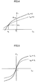
- FIG. 4 is a schematic drawing of a d-axis magnetic flux ⁇ d and a d-axis current command I dc according to the first embodiment of the present invention
- FIG. 5 is a schematic drawing of a q-axis magnetic flux ⁇ q and a q-axis current command I qc according to the first embodiment of the present invention
- FIG. 6 is a relation drawing 1 between the d-axis magnetic flux and the d-axis magnetic flux according to the first embodiment of the present invention
- FIG. 7 is a relation drawing 1 between the q-axis magnetic flux and the q-axis current according to the first embodiment of the present invention
- FIG. 8 is a relation drawing 2 between the d-axis magnetic flux and the d-axis current according to the first embodiment of the present invention
- FIG. 9 is a relation drawing 2 between the q-axis magnetic flux and the q-axis current according to the first embodiment of the present invention.
- FIG. 10 is a relation drawing between the d-axis magnetic flux and the d-axis current according to another function formula
- FIG. 11 is a relation drawing between the q-axis magnetic flux and the q-axis current according to another function formula
- FIG. 12 is a block diagram showing an internal configuration of a motor control unit according to a second embodiment of the present invention.
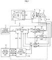
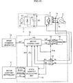
- FIG. 13 is a block diagram showing a system configuration of a third embodiment of the present invention.
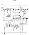
- FIG. 14 is a block diagram showing an internal configuration of the motor control unit according to the third embodiment of the present invention.
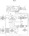
- FIG. 15 is a block diagram showing a system configuration of a fourth embodiment of the present invention.
- FIG. 16 is a block diagram showing an internal configuration of the motor control unit according to the fourth embodiment of the present invention.
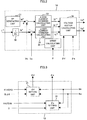
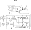
- FIG. 17 is a block diagram showing a system configuration of a fifth embodiment of the present invention.
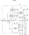
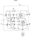
- FIG. 18 is a block diagram showing an internal configuration of a motor model according to the fifth embodiment of the present invention.
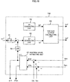
- FIG. 19 is a block diagram showing an internal configuration of the motor control unit according to the fifth embodiment of the present invention.
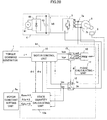
- FIG. 20 is a block diagram showing a system configuration of a sixth embodiment of the present invention.
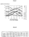
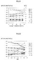
- FIG. 21 is a relation drawing 1 between a motor constant and rotor position according to the sixth embodiment of the present invention.
- FIG. 22 is an example 1 of motor constants in the sixth embodiment of the present invention.
- FIG. 23 is a block diagram showing an internal configuration of a state quantity calculating unit according to the sixth embodiment of the present invention.
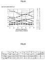
- FIG. 24 is a relation drawing 2 between the motor constant and the rotor position according to the sixth embodiment of the present invention.
- FIG. 25 is an example 2 of the motor constants in the sixth embodiment of the present invention.
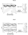
- FIG. 26 is a relation drawing between the d-axis magnetic flux and the rotor position according to the sixth embodiment of the present invention.
- FIG. 27 is a relation drawing between the q-axis magnetic flux and the rotor position according to the sixth embodiment of the present invention.
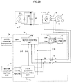
- FIG. 28 is a block diagram showing a system configuration according to a seventh embodiment of the present invention.
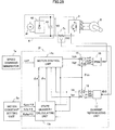
- FIG. 29 is a block diagram showing a system configuration according to an eighth embodiment of the present invention.
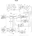
- FIG. 30 is a block diagram showing a system configuration according to a ninth embodiment of the present invention.
- FIG. 31 is a relation drawing between the motor constant and a magnet temperature according to the ninth embodiment of the present invention.
- FIG. 32 is a relation drawing between the motor constant and a residual magnetic flux density according to the ninth embodiment of the present invention.
- FIG. 33 is a block diagram showing an internal configuration of the state quantity calculating unit according to the ninth embodiment of the present invention.
- FIG. 34 is a relation drawing 1 between the d-axis magnetic flux and the d-axis current according to the ninth embodiment of the present invention.
- FIG. 35 is a relation drawing 2 between the d-axis magnetic flux and the d-axis current according to the ninth embodiment of the present invention.
- FIG. 36 is a block diagram showing a system configuration according to a tenth embodiment of the present invention.
- FIG. 37 is a block diagram showing a system configuration according to an eleventh embodiment of the present invention.
- FIG. 38 is a block diagram showing a system configuration according to a twelfth embodiment of the present invention.
- FIG. 39 is a block diagram showing an internal configuration of the state quantity calculating unit according to the twelfth embodiment of the present invention.
- a control unit for the AC motor according to the present invention In the embodiments blow a permanent magnet synchronous motor (hereinbelow abbreviated as a PM motor) will be described as the AC motor.
- PM motor permanent magnet synchronous motor
- the present invention is applicable to other motors (for example, wire-winding synchronous motors, reluctance motors, and induction motors).
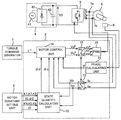
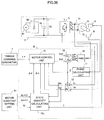
- FIG. 1 is a block diagram showing a system configuration of an AC motor control device according to a first embodiment of the present invention.
- the control device includes a torque command generator 1 for providing a motor a torque command ⁇ * to the motor, a controller 2 for calculating an AC applied voltage to the motor and converting it into a pulse width modulation signal (hereinafter abbreviated as PWM signal) to output the PWM signal, an inverter 3 driven by the PWM signal, a DC power supply 4 for supplying an electric power to an inverter 3 , a permanent magnet type synchronous motor 5 to be controlled (hereinbelow, abbreviated as PM motor), a position detector 6 for detecting a rotor position of the PM motor 5 , a current detector 7 a for detecting a current I u supplied to the PM motor 5 by the inverter 3 and a current detector 7 b for detecting a current I w , supplied to the PM motor 5 by the inverter 3 , and a motor constant setting unit 8
- the control unit 2 includes a phase calculating unit 11 for calculating a phase angle ⁇ of a rotor from a position of magnetic flux from the permanent magnet of the PM motor 5 detected by the position detector 6 , a dq coordinate converting unit 12 for converting the detected current I u , I w into components I dc , I qc on d- and q-axes orthogonal in rotary coordinate system of the motor, a state quantity calculating unit 13 for calculating and outputting d-axis component ⁇ d and q-axis component ⁇ q , which are state quantities of the PM motor, on the basis of the output of the motor constant setting unit 8 and the current detection values I dc , I qc , a motor control unit 14 for calculating voltage commands V d *, V q *, for driving the PM motor 5 on the basis of the torque command ⁇ *, the state quantities ⁇ d , ⁇ q of the PM motor, and the phase angle ⁇ , a dq coordinate
- the DC power supply 4 for supplying a power to the inverter 3 includes an AC power source 41 , a diode-bridge 42 for rectifying an AC voltage, and a smoothing capacitor 43 for suppressing pulsating components included in the DC power supply.
- the torque command ⁇ * is applied to the motor control unit 14 through a communication means of digital, analog, or the like from the torque command generator 1 .
- the AC currents I u , I w detected by the current detectors 7 a and 7 b are converted into current components I dc , I qc on the rotary coordinate axes (dq axes) by the dq coordinate converting unit 12 with the phase angle ⁇ calculated by the phase calculating unit 11 .
- the constants K 1 , K 2 , K 3 , K 4 , K 5 , K 6 , I 0 , ⁇ 0 , and I 1 outputted by the motor constant setting unit 8 and the detection currents I dc , I qc are applied to the state quantity calculating unit 13 which calculates the state quantities ⁇ d , ⁇ q in accordance with the current values and transmits the result to the motor control unit 14 .
- FIG. 2 shows a configuration of the motor control unit 14 .
- the configuration of the motor control unit 14 is substantially the same as an embodiment shown in FIG. 3 of the patent document 4.
- a different point is in that the state quantities ⁇ d , ⁇ q of the PM motor outputted by the state quantity calculating unit 13 are applied to a voltage vector calculating unit 36 to calculate the voltage command values V d *, V q * by the following equation.
- V d * R ⁇ I d ** ⁇ 1 * ⁇ q
- V q * R ⁇ I q **+ ⁇ 1 * ⁇ d (1)
- V d *, V q * are converted into AC quantities at the dq coordinate inverse converting unit 15 in accordance with the phase angle ⁇ and further converted at a PWM signal generating unit 16 into pulse width modulation signals sent to the inverter 3 .
- the state quantity calculating unit 13 includes a ⁇ d setting unit 21 and a ⁇ q setting unit 22 .
- the constants K 1 , K 2 , K 3 , I 0 , ⁇ 0 for calculating the d-axis component ⁇ d of the coil interlinkage flux as the state quantity of the motor are applied to the ⁇ d setting unit 21
- the constants K 4 , K 5 , K 6 , I 1 for calculating the q-axis component ⁇ q of the coil interlinkage flux are applied to the ⁇ q setting unit 22 .
- the detection current I dc , I qc are applied to the ⁇ d setting unit 21 and the ⁇ q setting unit 22 to calculate the ⁇ d and the ⁇ q in accordance with the current and respectively outputted.
- the ⁇ d setting unit 21 expresses the d-axis interlinkage flux ⁇ d as a function of a current I d on the d-axis and a current I q on the q axis and calculates the ⁇ d setting value by, for example, the function formula below featuring an influence of I dc I qc on ⁇ d from the inputted constants K 1 , K 2 , K 3 , I 0 , ⁇ 0 and the detection currents I dc , I qc , wherein the currents I dc , I qc are parameters.
- ⁇ d ⁇ ( I d ⁇ ⁇ c , I q ⁇ ⁇ c ) K 1 1 + K 2 ⁇ ⁇ I d ⁇ ⁇ c + I 0 ⁇ + K 3 ⁇ ⁇ I q ⁇ ⁇ c ⁇ ⁇ ( I d ⁇ ⁇ c + I 0 ) + ⁇ 0 ( 2 )
- the d-axis magnetic flux ⁇ d is a generally constant irrespective of the q-axis current I q and it is assumed that the d-axis current I d is ⁇ I 0 at that time. This relation will be shown in FIG. 4 .
- the ⁇ q setting unit 22 expresses the q-axis interlinkage flux ⁇ q as a function of the current I d on the d-axis and the current I q on the q axis and calculates with the I dc , I qc as parameters the ⁇ q setting value by, for example, the following function formula which features an influence of Ia dc , I qc on ⁇ q .
- I 1 is a value of the d-axis current I d when the q-axis magnetic flux of ⁇ q becomes a maximum.
- I 0 can be used in place of I 1 for simplification.
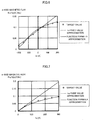
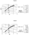
- FIG. 6 shows, in a case where a motor is exemplified, the d-axis current I d on an axis of abscissa, and the magnetic flux ⁇ d1 on an axis of ordinate, to show target values calculated by a magnetic flux analysis, approximation values calculated by equation (6) using L d as a fixed value and approximation values calculated by equation (8) which a functional formula of ⁇ d (I d , 0), for comparison.
- FIG. 6 shows, in a case where a motor is exemplified, the d-axis current I d on an axis of abscissa, and the magnetic flux ⁇ d1 on an axis of ordinate, to show target values calculated by a magnetic flux analysis, approximation values calculated by equation (6) using L d as a fixed value and approximation values calculated by equation (8) which a functional formula of ⁇ d (I d , 0), for comparison.
- ⁇ d , ⁇ q being the state quantities of the motor, are expressed by approximate equations such as ( ⁇ d (I d , I q ), ⁇ q (I d , I q ) in which the influence by the current of the other axis is considered in addition to the influence of the current of its own axis. Then the relation between the magnetic flux and the current are defined below.
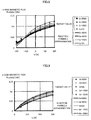
- FIG. 8 shows the magnetic flux ⁇ d when I d is represented on the axis of abscissa and I q is varied from 0 A, 100 A, 200 A, to 300 A regarding the target values calculated by a magnetic field analysis and approximation values calculated by the functional formula of Eq. (10) for comparison.
- FIG. 9 shows the magnetic flux ⁇ q when I q is represented on the axis of abscissa and I d is varied from ⁇ 200 A, ⁇ 100 A, 0 A, 100 A, and 200 A regarding the target values calculated by a magnetic field analysis and approximation values calculated by the functional formula of Eq. (11) for comparison.
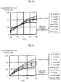
- FIG. 10 shows the magnetic flux ⁇ d when I d is represented on the axis of abscissa and I q is varied from 0 A, 100 A, 200 A, 300 A regarding the target values calculated by a magnetic field analysis and approximation values calculated by the functional formula of Eq. (13) for comparison.
- FIG. 11 shows the magnetic flux ⁇ q when I q is represented on the axis of abscissa and I d is varied from ⁇ 200 A, ⁇ 100 A, 0 A, 100 A, and 200 A regarding the target values calculated by a magnetic field analysis and approximation values calculated by the functional formula of Eq. (13) for comparison.
- FIGS. 10 and 11 it is shown that approximation in a region where current intensities are large is insufficient in comparison with the result of the functional formula approximation according to the present invention shown in FIGS. 8 and 9 . Particularly, the influence by the current on the other axis could not be accurately reproduced.
- the influence by the current on the other axis can more preferably approximate and more accurately express the influence of I d and I q on the d-axis magnetic flux ⁇ d and the q-axis magnetic flux ⁇ q even for a motor having a nonlinear characteristic in which influences of the magnetic saturation and the interference between the d-axis magnetic flux ⁇ d and the q-axis magnetic flux ⁇ q are large by using a method of approximating the influence by the current on the other axis with the functional formula approximation according to the present invention than approximating the influence by the current on the other axis with a higher order function.
- the state quantities of the motor are set with simple functional formulas in which the interference between the d-axis and q-axis magnetic flux can accurately and simply reproduce the nonlinear magnetic flux characteristic when the motor is driven with a heavy load and driven by a weak field control or the like.
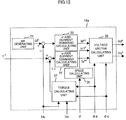
- the motor control unit 14 is replaced with a motor control unit 14 a shown in FIG. 12 .
- FIG. 12 is difference from FIG. 2 in that the conversion coefficient 32 is omitted and a torque calculating unit 37 is provided to calculate a torque estimation value ⁇ c .
- the state quantities 37 ⁇ d , ⁇ q of the PM motor outputted by the state quantity calculating unit 13 and the detected currents I dc , I qc are applied to the toque calculating unit 37 which calculates a torque estimation value ⁇ c with the functional formulas below.
- ⁇ c ⁇ d ⁇ I qc ⁇ q ⁇ I dc (14)
- the state quantities ⁇ d , ⁇ q of the PM motor outputted by the state quantity calculating unit 13 are used for the torque estimation calculation as mentioned above, which provides the torque control with a high accuracy and high response even if the electric constants of the motor vary because the motor current become large due to a heavy load.
- the configurations with the position sensor and current sensor are exemplified.
- configuration of a position-sensor-less-and-current-sensor-type can be provided.
- FIG. 13 is different from FIG. 1 as follows:
- the torque command generator 1 is replaced with a speed command generator 1 a .
- the motor control unit 14 is replaced with a motor control unit 14 b .
- the position detector 6 and the phase calculating unit 11 are omitted, and the phase angle ⁇ dc is supplied by the motor control unit 14 b.
- the configuration of the motor control unit 14 b in the third embodiment is substantially the same as FIG. 1 of the JP 2001-251889.
- the difference point is in that the state quantities ⁇ d , ⁇ q of the PM motor outputted by the state quantity calculating unit 13 are applied to a current feed forward compensating unit 56 and an induced voltage estimation and axis deviation calculating unit 57 to be used for calculation of V dm *, V qm *, ⁇ ,
- the induced voltage estimation and axis deviation calculating unit 57 calculates and outputs an induced voltage estimation value
- the state quantities ⁇ d , ⁇ q of the PM motor outputted by the state quantity calculating unit 13 are used for the above described calculation, which enables to obtain the rotor position information with a high accuracy and provides a high response even if the electric constants of the motor vary because the motor current become large due to a heavy load or the like.
- the configuration of the position-sensor-less-and-current-sensors type is exemplified.
- the present invention can be realized with a configuration of a position-sensor-less-and-current-sensor-less type. Description will be made with reference to FIG. 15 .
- FIG. 15 A different point of FIG. 15 from FIG. 13 is as follows: First, the current detector 7 a for detecting the current I u and the current detector 7 b for detecting the current I w are omitted, and a current detector 7 c is newly installed to detect a current IDC that the 4 supplies to the inverter 3 .
- a current reproducing unit 17 is newly installed which reproduces three-phase AC current I u , I v , I w flowing in the PM motor 5 by the method described in Patent document 3 or the like on the basis of the power supply current IDC detected by the current detector 7 c .
- the motor control unit 14 b is replaced with the motor control unit 14 c.
- the configuration of the motor control unit 14 c according to the fourth embodiment is substantially the same as FIGS. 1 and 6 of JP 2004-48868.
- the difference point is in that the state quantity calculating unit 13 inputs into a voltage vector calculating unit 64 and to a ⁇ 1 correcting unit 66 the state quantities ⁇ d , ⁇ q to be used for calculation of V d *, V q *, ⁇ w 1 .
- the ⁇ 1 correcting unit 66 calculates an axis deviation estimation value ⁇ and determines and outputs a value of ⁇ 1 by Eq. (18) so as to make the value zero.
- the state quantities ⁇ d , ⁇ q of the PM motor outputted by the state quantity calculating unit 13 are used for the above described calculation, which enables to obtain the rotor position information with a high accuracy and provides a high response even if the electric constants of the motor vary because the motor current become large due to a heavy load or the like.
- a fifth embodiment shows an example in which I d , I q are calculated from ⁇ d , ⁇ q after the functional formulas of the present invention are converted into inverse functions.
- FIG. 17 As described in the Transactions of the Institute of Electrical Engineers of Japan D, Vol 115, number 4, 420-427 pages, the present invention is applicable to a case where a motor model is provided inside the controller to perform a position-sensor-less control.
- FIG. 17 There is a difference in FIG. 17 from FIG. 15 as follows:
- the motor control unit 14 c is replaced with a motor control unit 14 d , the state quantity operation part 13 is omitted, and a motor model 18 is provided.
- the constants K 1 , K 2 , K 3 , K 4 , K 5 , K 6 , I 0 , ⁇ 0 , I 1 , and V d *, V q *, ⁇ 1 outputted by the motor control unit 14 d are inputted into a motor model 18 which outputs model currents I dm , I qm of the motor.
- the motor model 18 to which V d *, V q * are inputted and outputs model currents I dm , I qm of the motor.
- a calculation becomes necessary for outputting I dm , I qm from ⁇ d , ⁇ q as input.
- ⁇ d (I d , I q ) and ⁇ q (I d , I q ) in the present invention are fractional expressions in which the denominator and numerator are expressed with linear functions of currents as shown in Eq. (10) and (11). Accordingly, inverse functions can be made as shown by I d ( ⁇ d , ⁇ q ) and I q ( ⁇ d , ⁇ q ).
- an inverse function calculating unit 71 a can calculate I dm from ⁇ d , ⁇ q , and an inverse function calculating part 71 b can calculate I qm from ⁇ d , ⁇ q , so that a motor model operation in which a non-linearity is controlled.
- the motor control unit 14 d calculates a difference ⁇ I d between the model current I dm outputted by the motor model 18 and the detection current I dc , and a difference ⁇ I q between the model current L qm and the detected current I qc and estimates a rotor position O dc and a rotational speed ⁇ 1 in accordance with these values.
- FIG. 20 is different from FIG. 1 as follows: First, the controller 2 is replaced with a controller 2 d .
- the motor constant setting unit 8 is replaced with a motor constant setting unit 8 a .
- the state quantity calculating unit 13 is replaced with the state quantity calculating unit 13 a .
- the motor constant setting unit 8 a outputs twenty-four constants which are inputted into the state quantity calculating unit 13 a .
- the rotor phase angle ⁇ outputted by the phase calculating unit 11 is newly inputted into the state quantity calculating unit 13 a.
- FIG. 21 shows respective constants K 1 , K 2 , K 3 , K 4 , K 5 , K 6 , I 0 , ⁇ 0 in Eqs. (2) and (3) calculated for each rotor position.
- I 1 I 0
- respective constants are shown with values obtained by normalizing the constants with respect to a reference value.
- graphs of respective constants are frequency-analyzed to extract only six-order pulsation components having one cycle of an electrical angle of 60 degrees, the extracted pulsation components are shown as waveforms with curves.
- K 1 , K 2 , K 3 , K 4 , K 5 , K 6 , I 0 , ⁇ 0 each have pulsation components having one cycle of an electrical angle of 60 degrees, and can be approximated with Eq. (21) defined by an average value K ave , a pulsation amplitude K rip , and a phase K pha .
- Eq. (21) defined by an average value K ave , a pulsation amplitude K rip , and a phase K pha .
- the order of the pulsation is sixth order, “n” in Eq. (21) becomes 6.
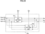
- FIG. 23 shows the state quantity calculating unit 13 a .
- FIG. 23 is different from FIG. 3 as follows:
- the ⁇ d setting unit 21 is replaced with a ⁇ d setting unit 21 a .
- the ⁇ q setting unit 22 is replace with a ⁇ q setting unit 22 a .
- Twenty-four constants outputted by the motor constant setting unit 8 a are inputted into the yd setting unit 21 a and the ⁇ q setting unit 22 a .
- the rotor phase angle ⁇ outputted by the phase calculating unit 11 is newly inputted into the ⁇ d setting unit 21 a and the ⁇ q setting unit 22 a.
- the ⁇ d setting unit 21 a expresses the d-axis interlinkage flux ⁇ d as a function of a current I d on the d-axis, a current I q on the q axis, and a rotor phase angle ⁇ and calculates the ⁇ d setting value by, for example, the function formula below featuring an influence of I dc , I qc , and ⁇ on ⁇ d from the currents I dc , I qc , and ⁇ as parameters, and has the constants K 1ave , K 2ave , K 3ave , K Iave , K ⁇ ave , K 1rip , K 2rip , K 3rip , K Irip , K ⁇ rip , K 1pha , K 2pha , K 3pha , K Ipha , K ⁇ pha , n.
- the ⁇ d setting value can be calculated with a functional formula below with assumption that a value of ⁇ d which is substantially constant irrespective of Iq is ⁇ 0 , and I d at that time is ⁇ I 0 , and that K 1ave , K 2ave , K 3ave , K 7ave , K 1rip , K 2rip , K 3rip , K 7rip , K 1pha , K 2pha , K 3pha , K 7pha , ⁇ 0 , I 0 , and n are constants
- Eq. (23) is different from Eq. (22) in that ⁇ 0 and I 0 becomes constants, and that a product of K 7 ( ⁇ ) variable in accordance with the rotor position and I qc is provided in the numerator.
- the ⁇ q setting unit 22 a expresses the q-axis interlinkage flux ⁇ q as a function of the current I d on the d-axis and the current I q on the q axis, and the rotor phase angle ⁇ and calculates from the inputted constants and the detection currents I dc , I qc , and ⁇ , wherein I dc , I qc , and ⁇ are parameters, the ⁇ q setting value by, for example, the function formulas below which feature an influence of I dc , I qc , and ⁇ on ⁇ q with constants K 4ave , K 5ave , K 6ave , K Iave , K 4rip , K 5rip , K 6rip , K 1rip , K 4pha , K 5pha , K 6pha , K Ipha .
- the ⁇ d setting value can be calculated with functional formulas having K 4ave , K 5ave , K 6ave , K 8ave , K 4rip , K 5rip , K 6rip , K 8rip , K 4pha , K 5pha , K 6pha , K 8pha , I 0 , and n are constants.
- FIG. 24 shows respective constants K 1 , K 2 , K 3 , K 4 , K 5 , K 6 , K 7 , and K 8 in Eqs. (23) and (25) calculated for each rotor position. Respective constants are shown with values obtained by normalizing the constants with respect to a reference value. In addition, graphs of respective constants are frequency-analyzed to extract only six-order pulsation components having one cycle of an electrical angle of 60 degrees, the extracted pulsation components are shown as waveforms with curves. In addition, average values K ave , pulsation amplitude K rip , a phase K pha are shown in FIG. 25 . As shown in FIG. 25 , the number of the constants when Eqs. (23) and (25) are used is 24 which the same as that in the case where Eq. (22) and (24) are used.
- the configuration with the position sensor and current sensor are exemplified.
- a configuration of the current sensor-less-and-position-sensor type can be provided. With reference to FIG. 28 , will be described this embodiment.
- FIG. 28 is different from FIG. 20 as follows: First, the controller 2 d is replaced with a controller 2 e .
- the torque command generator 1 is replaced with a speed command generator 1 a .
- the motor control unit 14 is replaced with the motor control unit 14 b .
- the position detector 6 and the phase calculating unit 11 are omitted, and the phase angle ⁇ dc is supplied by the motor control unit 14 b.
- ⁇ is replaced with ⁇ dc by the method described in the sixth embodiment.
- An operation of the motor control unit 14 b is provided by the method described in the third embodiment.
- the configuration of the current-sensor-less and the position-sensor type is exemplified.
- a configuration of the position-sensor-less-and-current-sensor-less type can be provided.
- FIG. 29 is different from FIG. 28 as follows:
- the controller 2 e is replaced with a controller 2 f .
- the current detector 7 a for detecting the current I U and the current detector 7 b for detecting the current I W are omitted and a current detector 7 c is newly provided to detect a current IDC supplied to the inverter 3 by the DC power supply 4 .
- a current reproducing unit 17 is newly installed which reproduces three-phase AC currents I U , I V , I W flowing through the PM motor 5 on the basis of the power supply current IDC detected by the current detector 7 c by a method described in, for example, Patent document 3.
- the motor control unit 14 b is replaced with a motor control unit 14 c.
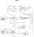
- the ninth embodiment considers not only the current-dependency but also a motor temperature dependency. This will be described with reference FIGS. 30 to 35 .
- FIG. 30 is different from FIG. 1 as follows:
- a temperature detector 9 for detecting a temperature of the PM motor 5 is added.
- the controller 2 is replaced with a controller 2 g .
- the motor constant setting unit 8 is replaced with a motor constant setting unit 8 b .
- the state quantity calculating unit 13 is replaced with a state quantity calculating unit 13 b .
- a Br calculating unit 19 is added.
- the temperature of the PM motor 5 detected by the temperature detector 9 is inputted into a calculator 19 .
- a residual magnetic flux density B r of a permanent magnet outputted by the Br calculating unit 19 is newly inputted into the state quantity calculating unit 13 b .
- the motor constant setting unit 8 b outputs eleven constants which are inputted into the state quantity calculating unit 13 b.
- FIG. 31 shows that the residual magnetic flux density B r when the temperature of the permanent magnet used in the rotor of the PM motor is varied from 20 to 180°, and respective constants K 1 , K 2 , K 3 , K 4 , K 5 , K 6 , I 0 , and ⁇ 0 in Eqs. (2) and (3) calculated on the basis of a magnetic field analysis according to a finite element method with the Br being set.
- I 1 I 0 and respective contestants are shown with values normalized with respect to a reference value.
- variations of respective constants regarding the magnet temperature are classified into three group, i.e., a group in which the constants are substantially constant irretentive of the temperature, a group in which the constants increase with increase in the temperature, and a group in which the constants decrease with increase in the temperature.
- the residual magnetic flux density B r decreases with increase in the temperature.
- a variation rate of B r with respect to the temperature increase is regarded to be substantially constant and the variation rate is shown as a temperature coefficients. Accordingly, in this embodiment, in a case where B r varies after the dependency on the motor temperature is converted into B r dependency, a method of calculating a magnetic flux which is a state quantity is shown.
- FIG. 32 shows respective constants when the value of B r is varied from 1.3 T to 0 T in which the residual magnetic flux density Br is taken on the axis of abscissa.
- respective constants K 1 , K 2 , K 3 , K 4 , K 5 , K 6 , I 0 , ⁇ 0 have features as follows:
- K 1 , K 3 , and K 5 can be regarded to be substantially constant because variations thereof are small with respect to B r .
- K 2 , K 4 , and K 6 vary in linear functions of B r .
- I 0 and ⁇ 0 are substantially proportional to B r .
- K 1 , K 3 , and K 5 are determined as fixed values irrespective of Br.
- K ( B r ) K c (26)
- K 2 , K 4 , and K 6 vary in linear functions.
- K ( B r ) K d ⁇ ( B r ⁇ B r0 )+ K c (27)
- I 0 , ⁇ 0 are approximately proportional to B r regarding a reference value at the room temperature.
- K ( B r ) K c ⁇ B r /B r0 (28)
- K c a constant value at the room temperature
- K d a variation rate of the constant with respect to variation of B r
- B r0 a value of B r at the room temperature.
- calculation of the state quantities considering the temperature dependency can be provided by setting a total of eleven constants including eight K c 's for K 1 , K 2 , K 3 , K 4 , K 5 , K 6 , I 0 , and ⁇ 0 , and three K d 's for K 2 , K 4 , and K 6 .
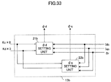
- FIG. 33 shows the state quantity calculating unit 13 b .
- FIG. 33 is different from FIG. 3 as follows:
- the ⁇ d setting unit 21 is replaced with a ⁇ d setting unit 21 b .
- the ⁇ q setting unit 22 is replaced with a ⁇ q setting unit 22 b .
- Eleven constants outputted by the motor constant setting unit 8 b are inputted into the ⁇ d setting unit 21 b and the ⁇ q setting unit 22 b .
- the residual magnetic flux density B r is newly inputted into the ⁇ d setting unit 21 b and the ⁇ q setting unit 22 b.
- the ⁇ d setting unit 21 b expresses the interlinkage flux ⁇ d on the d axis as a function of the current I d on the d axis, a current I q on the q axis, and the residual magnetic flux density B r and calculates ⁇ d setting value by, for example, the following function formula which features an influence of I dc , I qc , B r on ⁇ d from the inputted constants, the detection currents I dc , I qc , and B r wherein I dc , I qc , and B r are parameters and K 2d , K 2c , K Ic , K ⁇ c , K 1 , K 3 , and B r0 are constants.
- the ⁇ q setting unit 22 b expresses the interlinkage flux ⁇ q on the q axis as a function of the current I d on the d axis, a current I q on the q axis, and the residual magnetic flux density B r and calculates ⁇ q setting value by, for example, the following function formulas which feature influence of I dc , I qc , B r on ⁇ q from the inputted constants, the detection currents I dc , I qc , and the residual magnet field density B r wherein I dc , I qc , and B r are parameters and K 4d , K 4c , K 6d , K 6c , K Ic , K 5 , and B r0 are constants.
- FIG. 34 shows target values of ⁇ d calculated by magnetic flux analysis when the temperature of the permanent magnet is at normal temperature (20° C.) and I d and I q are varied on positive and negative sides and approximate values calculated by Eq. (29) for comparison.
- FIG. 35 shows target values of ⁇ q calculated by magnetic flux analysis when B r is set when the temperature of the permanent magnet is at 180° C. and I d and I q are varied on positive and negative sides and approximate values calculated by Eq. (30) for comparison.
- FIG. 36 is different from FIG. 30 as follows: First, the controller 2 g is replaced with a controller 2 h .
- the torque command generator 1 is replaced with a speed command generator 1 a .
- the motor control unit 14 is replaced with the motor control unit 14 b .
- the position detector 6 and the phase calculating unit 11 are omitted, and the phase angle ⁇ dc is supplied by the motor control unit 14 b.
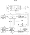
- FIG. 37 is different from FIG. 36 as follows:
- the controller 2 h is replaced with a controller 2 i .
- the current detector 7 a for detecting the current I U and the current detector 7 b for detecting the current I W are omitted, and a current detector 7 c is newly installed.
- the DC power source 4 detects a current IDC supplied to the inverter 3 by the DC power source 4 .
- a current reproducing unit 17 is newly installed which reproduces the three-phase AC currents I u , I v , I w flowing in the PM motor 5 on the basis of the power supply current IDC detected by the current detector 7 c by a method described in, for example, patent document 3.
- the motor control unit 14 b is replaced with the motor control unit 14 c.
- the dependency on the motor temperature is not converted in to B r dependency, but is directly used.
- FIG. 38 will be described the configuration.
- FIG. 38 is different from FIG. 30 as follows:
- the controller 2 g is replaced with a controller 2 j .
- the B r calculating unit 19 is omitted.
- the motor constant setting unit 8 b is replaced with motor constant setting unit 8 c .
- the state quantity calculating unit 13 b is replaced with a state quantity calculating unit 13 c .
- the temperature of the PM motor detected by the temperature detector 9 is directly inputted into the state quantity calculating unit 13 c . Twelve constants are outputted by the motor constant setting unit 8 c and inputted into the state quantity calculating unit 13 c.
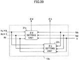
- FIG. 39 shows the state quantity calculating unit 13 c .
- FIG. 39 is different from FIG. 3 as follows:
- the ⁇ d setting unit 21 is replaced with a ⁇ d setting unit 21 c .
- the ⁇ q setting unit 22 is replaced with a ⁇ q setting unit 22 c .
- Twelve constants outputted by the motor constant setting unit 8 c are inputted into the ⁇ d setting unit 21 c and the ⁇ q setting unit 22 c .
- the motor temperature T outputted by the temperature detector 9 is newly inputted into the ⁇ d setting unit 21 c and the ⁇ q setting unit 22 c.
- Kt ⁇ B r / ⁇ T ⁇ 100/ B r (20° C.)(%/° C.) (31)
- ⁇ B r is a variation in quantity of B r
- ⁇ T is a variation in quantity of T
- B r (20° C.) is a value of B r at 20° C.
- Kt of a rear-earth magnet is about ⁇ 0.1%/° C.
- Kt of a ferrite magnet is about ⁇ 0.2%/° C.
- the ⁇ d setting unit 21 c expresses the interlinkage flux ⁇ d on the d axis as a function of the current I d on the d axis, the current I q on the q axis, and the motor temperature T and calculates ⁇ d setting value by, for example, the following functions which feature influence of I dc , I qc , and T on ⁇ d from the inputted constants, the detection currents I dc , I qc , and the motor temperature T wherein T 0 is, for example, a normal temperature (20° C.), I dc , I qc , and T are parameters and K 2d , K 2c , K Ic , K ⁇ c , K ⁇ c , K 1 , K 3 , B r0 , and K t are constants.
- the ⁇ q setting unit 22 b expresses the interlinkage flux ⁇ q on the q axis as a function of the current I d on the d axis, the current I q on the q axis, and the residual magnetic flux density B r and calculates ⁇ q setting value by, for example, the following functions which feature influence of I dc , I qc , and B r on ⁇ q from the inputted constants, the detection currents I dc , I qc , and the residual magnetic flux density B r , wherein T 0 is, for example, a normal temperature (20° C.), I dc , I qc , and B r are parameters, K 4d , K 4c , K 6d , K 6c , K Ic , K 5 , and B r0 are constants.
- the coil interlinkage flux ⁇ d , ⁇ q have been calculated as the state quantity of the motor and used. However, calculation can be made with current magnetic flux ⁇ id , ⁇ iq which is obtained by removing magnetic flux of the permanent magnet from the coil interlinkage flux, inductances La, L q , voltages V d , V q , currents I d , I q in place of calculating ⁇ d , ⁇ q .
- currents I d , I q are used as the state quantities.
- ⁇ d , ⁇ q , V d , and V q can be used as the state quantities in place of I d , I q .
- the example of the state quantity calculation to variation in the residual magnetic flux density B r of the permanent magnet motor is equivalent to variation in a field current of wound-field motor. Accordingly this is also applicable to the field current of wound-field motor.
Landscapes
- Engineering & Computer Science (AREA)
- Power Engineering (AREA)
- Control Of Ac Motors In General (AREA)
- Control Of Electric Motors In General (AREA)
Abstract
Description
- [Patent Document 1] JP 2001-161099
- [Patent Document 2] JP 2008-141835
- [Patent Document 3] JP 8-19263
- [Patent Document 4] JP 2004-297966
-
- a speed calculating unit configured to calculate a rotational speed of the AC motor,
V d *=R·I d**−ω1*·φq
V q *=R·I q**+ω1*·φd (1)
φd(I d,0)=L d ·I d +K e. (6)
φq(0,I q)=L q ·I q (7)
τc=φd ·I qc−φq ·I dc (14)
V dm *=R·I d*−ω1*·φq
V qm *=R·I q*+ω1*·φd (15)
K(θ)=K ave +K rip cos(nθ+K pha) (21)
K(B r)=K c (26)
K(B r)=K d·(B r −B r0)+K c (27)
K(B r)=K c ·B r /B r0 (28)
K t =ΔB r /ΔT×100/B r(20° C.)(%/° C.) (31)
- 1 torque command generator
- 1 a speed command generating unit
- 2, 2 a, 2 b, 2 c, 2 d, 2 e, 2 f, 2 g, 2 h, 2 i, 2 j controller
- 3 inverter
- 4 DC power supply
- 5 PM motor
- 6 position detector
- 7 a, 7 b, 7 c current detector
- 8, 8 a, 8 b, 8 c motor constant setting unit
- 9 motor temperature detector
- 11 phase calculating unit
- 12 dq coordinate converting unit
- 13, 13 a, 13 b, 13 c state quantity calculating unit
- 14, 14 a, 14 b, 14 c, 14 d motor control unit
- 15 dq coordinate inverse converting unit
- 16 PWM signal generating unit
- 17 current reproducing unit
- 18 motor model
- 19 Br calculating unit
- 21, 21 a, 21 b, 21 c φ d setting unit
- 22, 22 a, 22 b, 22 c φ q setting unit
- 31 Id generator
- 32 conversion coefficient
- 33 d-axis current command calculating unit
- 34 q-axis current command calculating unit
- 35 speed calculating unit
- 36 voltage vector calculating unit
- 37 torque calculating unit
- 41 AC power supply
- 42 diode bridge
- 43 smoothing capacitor
- 51 conversion gain
- 52 speed control unit
- 53 current command generating unit
- 54 d-axis current control unit
- 55 q-axis current control unit
- 56 current feed forward correcting unit
- 57 induced voltage estimation and axis deviation calculating unit
- 58 axis deviation error correcting unit
- 59 speed phase estimating unit
- 61 conversion gain
- 62 id* generating unit
- 63 iq* generating unit
- 64 voltage vector calculating unit
- 65, 73 a, 73 b integrating unit
- 66 ω1 correcting unit
- 67 position speed estimating unit
- 68 low-pass filter
- 71 a, 71 b inverse function calculating unit
- 72 a, 72 b resistance setting unit
- 74 a, 74 b ω1 setting unit
Claims (27)
Applications Claiming Priority (3)
| Application Number | Priority Date | Filing Date | Title |
|---|---|---|---|
| JP2009080853 | 2009-03-30 | ||
| JP2009-080853 | 2009-03-30 | ||
| PCT/JP2010/053123 WO2010116815A1 (en) | 2009-03-30 | 2010-02-26 | Ac motor control device and ac motor driving system |
Publications (2)
| Publication Number | Publication Date |
|---|---|
| US20120007528A1 US20120007528A1 (en) | 2012-01-12 |
| US8742704B2 true US8742704B2 (en) | 2014-06-03 |
Family
ID=42936103
Family Applications (1)
| Application Number | Title | Priority Date | Filing Date |
|---|---|---|---|
| US13/202,667 Expired - Fee Related US8742704B2 (en) | 2009-03-30 | 2010-02-26 | AC motor control device and AC motor driving system |
Country Status (5)
| Country | Link |
|---|---|
| US (1) | US8742704B2 (en) |
| JP (1) | JP5492192B2 (en) |
| CN (1) | CN102326329B (en) |
| DE (1) | DE112010001465T5 (en) |
| WO (1) | WO2010116815A1 (en) |
Cited By (3)
| Publication number | Priority date | Publication date | Assignee | Title |
|---|---|---|---|---|
| US20130181650A1 (en) * | 2010-10-08 | 2013-07-18 | Panasonic Corporation | Motor constant calculating method for pm motor, and motor constant calculating device |
| US20140346991A1 (en) * | 2013-05-21 | 2014-11-27 | IFP Energies Nouvelles | Method and system of internal temperatures determination in a synchronous electric machine using state observers |
| US20160036350A1 (en) * | 2013-04-12 | 2016-02-04 | Mitsubishi Electric Corporation | Power conversion device and motor driving device |
Families Citing this family (25)
| Publication number | Priority date | Publication date | Assignee | Title |
|---|---|---|---|---|
| JP2013143878A (en) * | 2012-01-12 | 2013-07-22 | Panasonic Corp | Inverter control device |
| JP5598767B2 (en) * | 2012-02-22 | 2014-10-01 | 株式会社デンソー | AC motor control device |
| JP5534252B2 (en) | 2012-02-22 | 2014-06-25 | 株式会社デンソー | AC motor control device |
| JP5621998B2 (en) | 2012-02-22 | 2014-11-12 | 株式会社デンソー | AC motor control device |
| JP5488845B2 (en) * | 2012-02-22 | 2014-05-14 | 株式会社デンソー | AC motor control device |
| JP5483218B2 (en) | 2012-02-22 | 2014-05-07 | 株式会社デンソー | AC motor control device |
| JP5698800B2 (en) * | 2013-06-25 | 2015-04-08 | ファナック株式会社 | Signal conditioning apparatus having termination resistance unit for terminating signal line |
| US11418140B2 (en) * | 2013-07-23 | 2022-08-16 | Atieva, Inc. | Induction motor flux and torque control |
| US10521519B2 (en) | 2013-07-23 | 2019-12-31 | Atieva, Inc. | Induction motor flux and torque control with rotor flux estimation |
| US9344026B2 (en) * | 2013-07-23 | 2016-05-17 | Atieva, Inc. | Induction motor flux and torque control |
| JP6098827B2 (en) * | 2014-01-31 | 2017-03-22 | 富士電機株式会社 | Control device for permanent magnet type synchronous motor |
| JP6108114B2 (en) * | 2014-01-31 | 2017-04-05 | 富士電機株式会社 | Control device for permanent magnet type synchronous motor |
| JP2015180130A (en) * | 2014-03-19 | 2015-10-08 | 富士電機株式会社 | Control device for permanent magnet type synchronous motor |
| CN104579089A (en) * | 2014-12-30 | 2015-04-29 | 广西科技大学 | Estimation method of rotating speed of permanent-magnet synchronous motor |
| CN107949982A (en) | 2015-08-08 | 2018-04-20 | 日本电产株式会社 | Motor controller and motor system |
| CN108616141B (en) * | 2018-03-13 | 2021-07-06 | 上海交通大学 | Power nonlinear control method of LCL grid-connected inverter in microgrid |
| CN108365791B (en) * | 2018-04-18 | 2021-01-12 | 沈阳工业大学 | AC motor coordinate system correction method aiming at stator winding deviation |
| JP7163640B2 (en) * | 2018-07-05 | 2022-11-01 | 富士電機株式会社 | Synchronous motor controller |
| JPWO2021054033A1 (en) | 2019-09-20 | 2021-03-25 | ||
| JP6879399B1 (en) * | 2020-02-14 | 2021-06-02 | 株式会社安川電機 | Power conversion device and power conversion method |
| JP7362523B2 (en) | 2020-03-17 | 2023-10-17 | 日立Astemo株式会社 | Synchronous machine control device, synchronous machine control method, and electric vehicle |
| CN112414287B (en) * | 2020-11-09 | 2021-12-28 | 北京理工大学 | A position calibration method of permanent magnet synchronous motor without current sensor |
| JP7162685B2 (en) * | 2021-02-04 | 2022-10-28 | 三菱電機株式会社 | AC rotary electric machine control device |
| CN118160213A (en) * | 2021-10-28 | 2024-06-07 | 三菱电机株式会社 | Power conversion devices, motor drive devices, and refrigeration cycle application equipment |
| CN114977972B (en) * | 2022-06-23 | 2025-09-09 | 中国第一汽车股份有限公司 | Motor control method and device and vehicle |
Citations (11)
| Publication number | Priority date | Publication date | Assignee | Title |
|---|---|---|---|---|
| JPH0819263A (en) | 1994-06-30 | 1996-01-19 | Meidensha Corp | Output current detector of pwm inverter |
| JPH0951700A (en) | 1995-05-31 | 1997-02-18 | Meidensha Corp | Controlling device of rotary electric machine |
| JPH09289799A (en) | 1996-04-19 | 1997-11-04 | Toyota Motor Corp | Permanent magnet motor controller |
| JP2001161099A (en) | 1999-11-30 | 2001-06-12 | Meidensha Corp | Control scheme for synchronous motor |
| JP2001251889A (en) | 2000-03-06 | 2001-09-14 | Hitachi Ltd | Method for estimating rotor position of synchronous motor, control method without position sensor, and control device |
| JP2004048868A (en) | 2002-07-10 | 2004-02-12 | Hitachi Ltd | Speed controller for synchronous motor |
| JP2004297966A (en) | 2003-03-28 | 2004-10-21 | Hitachi Ltd | AC motor control device |
| US20060239047A1 (en) * | 2003-09-30 | 2006-10-26 | Manabu Yoshimura | Inverter apparatus |
| US20080129243A1 (en) | 2006-11-30 | 2008-06-05 | Denso Corporation | System and method for controlling motor using parameter associated with magnetic flux |
| DE112007000033T5 (en) | 2006-03-31 | 2008-06-19 | Aisin AW Co., Ltd., Anjo | Electric drive control apparatus and electric drive control method |
| JP2009136085A (en) | 2007-11-30 | 2009-06-18 | Hitachi Ltd | AC motor control device |
Family Cites Families (3)
| Publication number | Priority date | Publication date | Assignee | Title |
|---|---|---|---|---|
| EP1906523A4 (en) * | 2005-07-11 | 2012-10-10 | Hitachi Ltd | CONTROL FOR A SYNCHRONOUS MOTOR OF THE FIELD WINDING TYPE, ELECTRIC DRIVING SYSTEM, ELECTRIC FOUR-WHEELED VEHICLE AND HYBRID AUTOMOBILE |
| KR101203975B1 (en) | 2006-05-19 | 2012-11-23 | 엘지전자 주식회사 | Refrigerator |
| JP4654217B2 (en) * | 2007-04-25 | 2011-03-16 | 日立オートモティブシステムズ株式会社 | Field weakening control device for permanent magnet motor and electric power steering using the same |
-
2010
- 2010-02-26 US US13/202,667 patent/US8742704B2/en not_active Expired - Fee Related
- 2010-02-26 DE DE112010001465T patent/DE112010001465T5/en not_active Withdrawn
- 2010-02-26 CN CN201080008724.0A patent/CN102326329B/en not_active Expired - Fee Related
- 2010-02-26 WO PCT/JP2010/053123 patent/WO2010116815A1/en active Application Filing
- 2010-02-26 JP JP2011508275A patent/JP5492192B2/en not_active Expired - Fee Related
Patent Citations (13)
| Publication number | Priority date | Publication date | Assignee | Title |
|---|---|---|---|---|
| JPH0819263A (en) | 1994-06-30 | 1996-01-19 | Meidensha Corp | Output current detector of pwm inverter |
| JPH0951700A (en) | 1995-05-31 | 1997-02-18 | Meidensha Corp | Controlling device of rotary electric machine |
| JPH09289799A (en) | 1996-04-19 | 1997-11-04 | Toyota Motor Corp | Permanent magnet motor controller |
| JP2001161099A (en) | 1999-11-30 | 2001-06-12 | Meidensha Corp | Control scheme for synchronous motor |
| JP2001251889A (en) | 2000-03-06 | 2001-09-14 | Hitachi Ltd | Method for estimating rotor position of synchronous motor, control method without position sensor, and control device |
| JP2004048868A (en) | 2002-07-10 | 2004-02-12 | Hitachi Ltd | Speed controller for synchronous motor |
| JP2004297966A (en) | 2003-03-28 | 2004-10-21 | Hitachi Ltd | AC motor control device |
| US20060239047A1 (en) * | 2003-09-30 | 2006-10-26 | Manabu Yoshimura | Inverter apparatus |
| DE112007000033T5 (en) | 2006-03-31 | 2008-06-19 | Aisin AW Co., Ltd., Anjo | Electric drive control apparatus and electric drive control method |
| US7489099B2 (en) | 2006-03-31 | 2009-02-10 | Aisin Aw Co., Ltd. | Electrical drive control device and electrical drive control method |
| US20080129243A1 (en) | 2006-11-30 | 2008-06-05 | Denso Corporation | System and method for controlling motor using parameter associated with magnetic flux |
| JP2008141835A (en) | 2006-11-30 | 2008-06-19 | Denso Corp | Motor control method and motor control device using the same |
| JP2009136085A (en) | 2007-11-30 | 2009-06-18 | Hitachi Ltd | AC motor control device |
Non-Patent Citations (1)
| Title |
|---|
| German Office Action dated Dec. 6, 2012 issued in corresponding German Patent Application No. 112010001465.5. |
Cited By (6)
| Publication number | Priority date | Publication date | Assignee | Title |
|---|---|---|---|---|
| US20130181650A1 (en) * | 2010-10-08 | 2013-07-18 | Panasonic Corporation | Motor constant calculating method for pm motor, and motor constant calculating device |
| US9024562B2 (en) * | 2010-10-08 | 2015-05-05 | Panasonic Intellectual Property Management Co., Ltd. | Motor constant calculating method for PM motor, and motor constant calculating device |
| US20160036350A1 (en) * | 2013-04-12 | 2016-02-04 | Mitsubishi Electric Corporation | Power conversion device and motor driving device |
| US9531301B2 (en) * | 2013-04-12 | 2016-12-27 | Mitsubishi Electric Corporation | Power conversion device and motor driving device |
| US20140346991A1 (en) * | 2013-05-21 | 2014-11-27 | IFP Energies Nouvelles | Method and system of internal temperatures determination in a synchronous electric machine using state observers |
| US9383265B2 (en) * | 2013-05-21 | 2016-07-05 | IFP Energies Nouvelles | Method and system of internal temperatures determination in a synchronous electrical machine using state observers |
Also Published As
| Publication number | Publication date |
|---|---|
| WO2010116815A1 (en) | 2010-10-14 |
| JP5492192B2 (en) | 2014-05-14 |
| DE112010001465T5 (en) | 2012-05-16 |
| CN102326329B (en) | 2015-12-16 |
| CN102326329A (en) | 2012-01-18 |
| JPWO2010116815A1 (en) | 2012-10-18 |
| US20120007528A1 (en) | 2012-01-12 |
Similar Documents
| Publication | Publication Date | Title |
|---|---|---|
| US8742704B2 (en) | AC motor control device and AC motor driving system | |
| JP5420006B2 (en) | Synchronous machine controller | |
| Qu et al. | Loss-minimizing flux level control of induction motor drives | |
| JP5156352B2 (en) | AC motor control device | |
| CN103931096B (en) | Method and system with function of temperature compensation control motor | |
| JP3467961B2 (en) | Control device for rotating electric machine | |
| JP5781235B2 (en) | Synchronous machine controller | |
| US8450955B2 (en) | Alternating-current motor control apparatus | |
| EP2830211B1 (en) | Control device for three-phase ac induction motor and control method for three-phase ac induction motor | |
| CN103733504B (en) | The position-sensorless control device of PM motor | |
| CN108011556A (en) | Sensorless control system for permanent magnet synchronous motor | |
| EP3373444B1 (en) | Apparatus for estimating initial position of rotor of motor | |
| KR101449872B1 (en) | A modified current control scheme of Permanent Magnet Synchronous Motor | |
| US12143038B2 (en) | Rotary machine control device | |
| JP2006304478A (en) | Motor drive control device and electric power steering device using the same | |
| JPH09238492A (en) | AC motor control device | |
| CN103187910B (en) | Apparatus for controlling interior permanent magnet synchronous motor | |
| JP6108114B2 (en) | Control device for permanent magnet type synchronous motor | |
| JP5652701B2 (en) | Motor drive control device | |
| JP4984057B2 (en) | Control device for permanent magnet type synchronous motor | |
| Jouili et al. | Regular paper I mplementation of Sensorless Speed Control for I nduction Motor drive Using I RFOC | |
| JP2023089904A (en) | Rotating machine control device | |
| JP2025034442A (en) | Motor control device and control method | |
| JP2005269818A (en) | Multi-phase AC current controller | |
| JP5532693B2 (en) | Induction motor control device |
Legal Events
| Date | Code | Title | Description |
|---|---|---|---|
| AS | Assignment |
Owner name: HITACHI, LTD., JAPAN Free format text: ASSIGNMENT OF ASSIGNORS INTEREST;ASSIGNORS:NAKATSUGAWA, JUNNOSUKE;IWAJI, YOSHITAKA;IWASAKI, NORIHISA;AND OTHERS;SIGNING DATES FROM 20110801 TO 20110803;REEL/FRAME:026856/0649 |
|
| STCF | Information on status: patent grant |
Free format text: PATENTED CASE |
|
| MAFP | Maintenance fee payment |
Free format text: PAYMENT OF MAINTENANCE FEE, 4TH YEAR, LARGE ENTITY (ORIGINAL EVENT CODE: M1551) Year of fee payment: 4 |
|
| FEPP | Fee payment procedure |
Free format text: MAINTENANCE FEE REMINDER MAILED (ORIGINAL EVENT CODE: REM.); ENTITY STATUS OF PATENT OWNER: LARGE ENTITY |
|
| LAPS | Lapse for failure to pay maintenance fees |
Free format text: PATENT EXPIRED FOR FAILURE TO PAY MAINTENANCE FEES (ORIGINAL EVENT CODE: EXP.); ENTITY STATUS OF PATENT OWNER: LARGE ENTITY |
|
| STCH | Information on status: patent discontinuation |
Free format text: PATENT EXPIRED DUE TO NONPAYMENT OF MAINTENANCE FEES UNDER 37 CFR 1.362 |
|
| FP | Lapsed due to failure to pay maintenance fee |
Effective date: 20220603 |