US8717455B2 - Image processing apparatus and image processing method - Google Patents
Image processing apparatus and image processing method Download PDFInfo
- Publication number
- US8717455B2 US8717455B2 US13/086,682 US201113086682A US8717455B2 US 8717455 B2 US8717455 B2 US 8717455B2 US 201113086682 A US201113086682 A US 201113086682A US 8717455 B2 US8717455 B2 US 8717455B2
- Authority
- US
- United States
- Prior art keywords
- image
- change amount
- plane image
- distance information
- depth
- Prior art date
- Legal status (The legal status is an assumption and is not a legal conclusion. Google has not performed a legal analysis and makes no representation as to the accuracy of the status listed.)
- Active, expires
Links
Images


Classifications
-
- H—ELECTRICITY
- H04—ELECTRIC COMMUNICATION TECHNIQUE
- H04N—PICTORIAL COMMUNICATION, e.g. TELEVISION
- H04N5/00—Details of television systems
- H04N5/222—Studio circuitry; Studio devices; Studio equipment
- H04N5/262—Studio circuits, e.g. for mixing, switching-over, change of character of image, other special effects ; Cameras specially adapted for the electronic generation of special effects
- H04N5/2621—Cameras specially adapted for the electronic generation of special effects during image pickup, e.g. digital cameras, camcorders, video cameras having integrated special effects capability
-
- G—PHYSICS
- G06—COMPUTING OR CALCULATING; COUNTING
- G06T—IMAGE DATA PROCESSING OR GENERATION, IN GENERAL
- G06T5/00—Image enhancement or restoration
- G06T5/70—Denoising; Smoothing
-
- H—ELECTRICITY
- H04—ELECTRIC COMMUNICATION TECHNIQUE
- H04N—PICTORIAL COMMUNICATION, e.g. TELEVISION
- H04N13/00—Stereoscopic video systems; Multi-view video systems; Details thereof
- H04N13/10—Processing, recording or transmission of stereoscopic or multi-view image signals
- H04N13/106—Processing image signals
- H04N13/128—Adjusting depth or disparity
-
- G—PHYSICS
- G06—COMPUTING OR CALCULATING; COUNTING
- G06T—IMAGE DATA PROCESSING OR GENERATION, IN GENERAL
- G06T2207/00—Indexing scheme for image analysis or image enhancement
- G06T2207/20—Special algorithmic details
- G06T2207/20172—Image enhancement details
- G06T2207/20201—Motion blur correction
-
- H—ELECTRICITY
- H04—ELECTRIC COMMUNICATION TECHNIQUE
- H04N—PICTORIAL COMMUNICATION, e.g. TELEVISION
- H04N13/00—Stereoscopic video systems; Multi-view video systems; Details thereof
- H04N13/10—Processing, recording or transmission of stereoscopic or multi-view image signals
- H04N13/106—Processing image signals
- H04N13/122—Improving the 3D impression of stereoscopic images by modifying image signal contents, e.g. by filtering or adding monoscopic depth cues
Definitions
- the present invention relates to an image processing apparatus and image processing method and, more particularly, to an image processing apparatus and image processing method for performing an image process to reconstruct the composition of a captured image.
- the spread of digital cameras boosts the opportunity to capture still and moving images on travels, at events, and the like.
- the user views a captured image, he may have a different impression between a capturing target during capturing and an image after capturing (to be referred to as a captured image).
- demand has arisen for an editing function of dividing a captured image into a region where an important subject is captured (to be referred to as an important-subject region) and a background region, transforming the important-subject region, and reconstructing the composition to generate an image as if the image were captured again.
- the region of a captured image is divided, and a blur corresponding to the distance is applied to each region using separately-obtained distance information.
- a hemispherical 3D virtual space is created from a captured image, and the model of each region is arranged in the virtual space so that the composition in the captured image can be changed.
- an image processing apparatus comprising: a changing section, configured to change an area of a subject image in an image; a determiner, configured to determined a correction strength based on an area-change amount between an area before an area change and an area after the area change for the subject image whose area has been changed; and a corrector, configured to perform a correction process for the image in accordance with the correction strength.
- an image processing method comprises: using a processor to perform the steps of: changing an area of a subject image in an image; determining a correction strength based on an area-change amount between an area before an area change and an area after the area change for the subject image whose area has been changed; and performing a correction process for the image in accordance with the correction strength.
- a correction process can be performed in accordance with a change of the composition of a captured image.
- FIG. 1 is a block diagram for illustrating the arrangement of an image processing apparatus according to an embodiment.
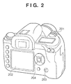
- FIG. 2 is a perspective view for illustrating an example of a camera in which the image processing apparatus according to the embodiment is assembled.
- FIG. 3 is a flowchart for illustrating an image process according to the embodiment.
- FIG. 4 is a flowchart for illustrating a determination of whether input image data is correctable image data, and generation of correctable image data.
- FIGS. 5A to 5D are views for illustrating the generation of correctable image data.
- FIG. 6 is a flowchart for illustrating the transformation of a target region.
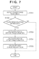
- FIG. 7 is a flowchart for illustrating the calculation of the area-change amount.
- FIG. 8 is a flowchart for illustrating a process of calculating the depth after a transformation process from the area-change amount.
- FIGS. 9A to 9C are views for illustrating the calculation of the depth after the transformation process.
- FIG. 10 is a flowchart for illustrating a process of setting a blur function.
- FIG. 11 is a flowchart for illustrating a correction process according to the second embodiment.
- FIG. 12 is a flowchart for illustrating a correction process according to the third embodiment.
- FIG. 13 is a flowchart for illustrating a correction process according to the fourth embodiment.
- a microprocessor (CPU) 111 controls the following components by executing a program stored in a read-only memory (ROM) 112 using a random access memory (RAM) 113 as a work memory.
- the ROM 112 stores control programs and data for the camera, and programs and data for various processes.
- a capturing unit 101 includes various lenses for zooming, focusing, and camera-shake correction, a stop, a shutter, an optical low-pass filter, an infrared cut filter, a color filter, and a sensor such as a complementary metal oxide semiconductor (CMOS) or charge coupled device (CCD).
- CMOS complementary metal oxide semiconductor
- CCD charge coupled device
- a capturing data input unit 102 converts an analog signal input from the capturing unit 101 into a digital signal.
- a signal processing unit 103 performs various image processes, such as demosaicing, white-balance correction, and gamma correction for a digital signal input from the capturing data input unit 102 , generating a digital image.
- a display unit 105 such as a liquid crystal display (LCD) displays a digital image input via a display interface (I/F) 104 , and displays various images including sign and character images which are input from an image generation unit 114 .
- the display unit 105 may have a touch-screen function. In this case, the display unit 105 also functions as part of an operation unit 109 for inputting a user instruction.
- An encoder 106 converts a digital image input from the signal processing unit 103 into compressed image data or video data of a format such as JPEG, MPEG, or H.264 in accordance with an instruction from the CPU 111 .
- Image data or video data output from the encoder 106 is stored in a medium (for example, hard disk or memory card) 120 via a medium I/F 107 which controls read/write from/in the medium 120 mounted in the digital camera.
- the medium I/F 107 also functions as an interface for connecting the image processing apparatus to a computer device (PC).
- a capturing system control unit 108 controls the capturing unit 101 to, for example, adjust the focus, open/close the shutter, or adjust the stop in accordance with an instruction from the CPU 111 .
- the operation unit 109 inputs a user instruction via an input unit such as a button, a mode dial, a switch, or the above-mentioned touch screen. User instructions regarding the zoom, focus, shutter speed, aperture value, and capturing mode can also be input via the operation unit 109 .
- a distance information obtaining unit 110 includes a sensor for measuring the distance from the digital camera to a subject in capturing. Distance information measured by the distance information obtaining unit 110 is added to image data of a captured image or stored in the medium 120 in association with the image data.
- the digital camera in which the image processing apparatus according to the embodiment is assembled will be exemplified with reference to FIG. 2 .
- a monitor 202 corresponds to the display unit 105 , and displays an image and various kinds of information.
- the monitor 202 is used to display video captured by the capturing unit 101 or signs and characters which form a user interface, or play back and display-image data, video data, or the like stored in the medium 120 .
- a mode switch 203 is an input unit for switching the camera-operation mode.
- the user operates the mode switch 203 to switch the camera to, for example, a state (to be referred to as a capturing state) in which an image can be captured or a state (to be referred to as a playback state) in which a captured image or captured video is played back and displayed on the display unit 105 .
- playback display is not limited to the display unit 105 and can also be done using an external monitor via the medium I/F 107 .
- a four-way selector key 204 is an input unit which has four buttons arranged at the top, bottom, right, and left and a setting button arranged at the center, and designates selection or execution of a menu item or the like displayed on the monitor 202 .
- the user operates the four-way selector key 204 for selection of a captured image to undergo playback display, selection of video, a fast-forward process, reverse playback, or the like.
- a release button 201 is an input unit for designating focusing and capturing.
- the digital camera When the digital camera is set in the still-image capturing mode, the user captures a still image by pressing the release button 201 in a non-capturing state.
- the digital camera When the digital camera is set in the moving-image capturing mode, the user starts capturing a moving image by pressing the release button 201 in a non-capturing state, and ends the capturing by pressing the release button 201 in the capturing state.
- the CPU 111 executes this process when the camera is in the playback state and, for example, the user designates an image correction process via the operation unit 109 .
- the CPU 111 inputs image data to be corrected among image data stored in, for example, the medium 120 (loads image data into the RAM 113 ) (step S 301 ).
- the CPU 111 determines whether the input image data is correctable image data (step S 302 ). If the input image data is uncorrectable image data, the CPU 111 divides an image represented by the image data into regions using distance information in capturing, generating correctable image data (step S 303 ). Note that details of generation of correctable image data will be described later.
- the generated correctable image data can be stored in the medium 120 in association with the captured image. In other words, when correctable image data corresponding to image data designated by the user is stored in the medium 120 or the like, the CPU 111 can input the correctable image data.
- the CPU 111 displays an image represented by the image data on the display unit 105 (step S 304 ), and inputs a target region selected by the user (step S 305 ).
- the user moves a cursor displayed on the image to, for example, the diagonal vertex of a region, and presses the setting button of the four-way selector key 204 to select the target region.
- the image generation unit 114 may color a transformable region or the selected region to assist the user operation.
- the CPU 111 transforms the target region (step S 306 ), and determines whether the target region has been transformed (step S 307 ). If the target region has not been transformed, the image process ends. Transformation of the target region will be described later.
- the CPU 111 calculates the change amount of the area (to be referred to as area-change amount) of the target region (step S 308 ). Based on the area-change amount, the CPU 111 calculates distance information (to be referred to as depth) in the direction of depth in the 2.5D space (step S 309 ), details of which will be described later. Note that the expression “2.5D space” means adding the depth to a 2D image.
- the CPU 111 sets a blur function corresponding to the change amount of the depth before and after the transformation process, and performs a correction process using the blur function (step S 310 ).
- the CPU 111 displays the image having undergone the correction process on the display unit 105 (step S 311 ). Image data of the corrected image may be stored in the medium 120 or output to a PC or the like.
- step S 302 A determination of whether input image data is correctable image data (step S 302 ), and generation of correctable image data (step S 303 ) will be explained with reference to the flowchart of FIG. 4 .
- the CPU 111 determines whether input image data is image data in the 2.5D space (step S 401 ). If the input image data is image data in the 2.5D space, the CPU 111 determines that the input image data is correctable image data, and ends the process. Note that image data in the 2.5D space will be described later.
- the CPU 111 obtains distance information indicating the distance between the camera and the subject in correspondence with the input image data (step S 402 ).
- the CPU 111 normalizes the distance information based on shooting-distance ranges (to be referred to as distance ranges), and creates an image (to be referred to as a depth map) having three regions corresponding to the distance ranges (step S 403 ).
- the simplest distance ranges are three ranges such as a near distance (short range) of up to 5 m (inclusive), a middle distance (middle range) of 5 m (exclusive) to 500 m (inclusive), and a far distance (distant range) of more than 500 m.
- the user can operate the operation unit 109 to set the number of distance ranges and the distance range of each range.
- FIG. 5A exemplifies a captured image.
- FIG. 5B exemplifies a depth map corresponding to the captured image in FIG. 5A .
- the low-density region represents the short range
- the intermediate-density region represents the middle range
- the high-density region represents the distant range.
- the CPU 111 makes the depth map and captured image correspond to each other, and divides the image into regions for the respective densities (distance ranges) of the depth map (step S 404 ).
- the division precision can be increased by detecting image edges and performing region division based on the correspondence between the regions of the depth map and the detected edges.
- the CPU 111 generates plane images by surrounding the divided regions by rectangular frames, and separates the respective plane images (step S 405 ).
- the vertical and horizontal sides of the rectangular frame are parallel to those of the image, respectively.
- the solid line indicates the rectangular frame.
- the rectangular frame has a thickness of 0 and is invisible.
- a portion other than the divided region does not have data, and is set to be transparent by giving a pixel value indicating transparency or setting transparent data in the a channel.
- the CPU 111 generates a 2.5D image by arranging the plane images in the direction of depth (Z-axis direction) in the 3D space in accordance with their distance ranges (step S 406 ).
- the CPU 111 then ends the process.
- image data obtained by arranging plane images in the 3D space (image data in the 2.5D space serving as a set of plane image data each having information indicating the depth (to be referred to as depth information)) is correctable image data.
- a 2D space (X-Y space) in which plane images have the same depth information will be called a layer.
- step S 306 Transformation of a target region (step S 306 ) will be explained with reference to the flowchart of FIG. 6 .
- the CPU 111 selects a layer containing a plane image to be transformed based on target region selection information (step S 601 ), and accepts a user operation input from the operation unit 109 (step S 602 ).
- the user can transform (enlarge, reduce, or rotate) a plane image contained in a selected layer by designating the transformation amount.
- the CPU 111 changes the size of each plane image on the selected layer by the designated transformation amount while maintaining the aspect ratio. If the user designates rotation, the CPU 111 rotates each plane image of the selected layer at a designated angle (transformation amount) using the center of the entire captured image as the rotation axis. The CPU 111 then calculates the pixel value of each plane image after the transformation process. Note that the transparent portion of the plane image is kept transparent even after the transformation process for the plane image. The user can also designate the center of rotation.
- the CPU 111 branches the process in accordance with a user instruction (step S 603 ). If the user designates an enlargement process, the CPU 111 performs the above-described enlargement process (step S 604 ). If the user designates a reduction process, the CPU 111 performs the above-described reduction process (step S 605 ). If the user designates a rotation process, the CPU 111 performs the above-described rotation process (step S 606 ). Note that the enlargement/reduction process employs a bilinear method, bicubic method, or the like, and the rotation process adopts affine transformation or the like.
- the CPU 111 performs a process of interpolating a blank portion which is generated by reducing or rotating the plane image of a selected layer and has lost pixel information (step S 607 ).
- the blank portion is interpolated using pixel information of a region close in spatial distance to the blank portion in the plane image of a layer other than the selected one.
- image data to be corrected is one of successively captured photographic images or moving image frames, it is also possible to detect a region corresponding to the blank portion from photographic images or frames captured before and after capturing of the image data to be corrected, and interpolate the blank portion using pixel information of the detected region.
- the CPU 111 displays the image having undergone the transformation process on the display unit 105 (step S 608 ), and waits for a user instruction (step S 609 ). If the user designates further transformation, the CPU 111 returns the process to step S 602 . If the user designates re-execution of transformation, the CPU 111 discards the transformation result (step S 610 ), and returns the process to step S 601 . If the user designates the end of transformation, the CPU 111 ends the transformation process. Note that the CPU 111 can parallelly or alternately display images before and after the transformation process on the display unit 105 to present the transformation result (effect).
- step S 308 Calculation of the area-change amount (step S 308 ) will be explained with reference to the flowchart of FIG. 7 .
- the CPU 111 detects the transformed plane image (step S 701 ), and determines whether the detected plane image has been enlarged or reduced (step S 702 ). If the detected plane image has been enlarged or reduced, the CPU 111 calculates the area (for example, pixel count) S 1 of the plane image before the transformation process (step S 703 ), calculates the area S 2 after the transformation process (step S 704 ), and calculates the area-change amount S 2 /S 1 (step S 705 ).
- the area for example, pixel count
- a high-precision area-change ratio can be obtained by calculating the area-change ratio of a plane image having a maximum area among a plurality of plane images, and setting it as the area-change ratio of the target region.
- step S 309 The process of calculating the depth after the transformation process from the area-change amount (step S 309 ) will be explained with reference to the flowchart of FIG. 8 .
- the CPU 111 obtains the area-change amount of a target region (step S 801 ), obtains the distance range (depth) Z of the target region (step S 802 ), and obtains the width (length along the X-axis) W′ of the rectangular frame after the transformation process (step S 803 ). Then, the CPU 111 calculates the depth Z′ of the target region after the transformation process (depth after the transformation process) in accordance with equation (1) (step S 804 ):
- W is the width of the rectangular frame of the target region before the transformation process
- S 2 /S 1 is the area-change ratio.
- FIG. 9A shows a triangle corresponding to the depth Z and the width W of a rectangular frame before the transformation process.
- FIG. 9B shows a triangle corresponding to the depth Z and the width W′ of a rectangular frame after the transformation process. More specifically, the CPU 111 calculates the depth Z′ at which the areas of the triangles before and after the transformation process coincide with each other ( FIG. 9C ). Note that the height (length along the Y-axis) H of the rectangular frame may be used instead of the width W.
- step S 310 The process of setting a blur function (step S 310 ) will be explained with reference to the flowchart of FIG. 10 .
- the blur function is set using, for example, a simulation model which simulates the degree of blur of the lens, it may be set by another method.
- the CPU 111 obtains the depths Z and Z′ of a target region before and after the transformation process (step S 1001 ), and sets a blur function corresponding to the depth-change amount Z′/Z (step S 1002 ).
- the blur correction strength is increased for Z′/Z>1 (reduction), and decreased for Z′/Z ⁇ 1 (enlargement).
- the CPU 111 corrects the plane image of a layer containing the target region (step S 1003 ).
- Processing using not only a change of the depth but also information of the focal length of the photographing lens when the image was captured is also possible.
- a sharpness process is performed at a correction strength corresponding to the depth-change amount.
- a blur process is executed at a correction strength corresponding to the depth-change amount.
- All plane images contained in the layer may undergo the blur (or sharpness) process at the same correction strength.
- the blur (or sharpness) process may be done at a correction strength corresponding to the depth of each layer or each region.
- the depth difference in the short range or the middle range may greatly affect the image impression.
- a captured image is divided into regions using the distance information, and depth information is added to a layer containing a plane image corresponding to each divided region, generating image data in the 2.5D space.
- the composition is changed by transforming the region of the captured image, the captured image is sometimes observed as if the depth of the transformed region changed.
- the depth-change amount is calculated, and the blur process or sharpness process is done in accordance with the depth-change amount.
- the image data in the 2.5D space is handled, so the processing load can be suppressed compared to handling image data in the 3D space.
- the editing function of reconstructing the composition can therefore be assembled into an image input device such as a digital camera. For example, when the user forgets to take an effective long shot, he can generate a long shot image from a captured image in video editing using the editing function of reconstructing the composition.
- the first embodiment has described an example of reducing unnaturalness of an image after the transformation process by performing the blur process or sharpness process at a correction strength corresponding to the depth-change amount of a target region along with transformation of the target region.
- the second embodiment will explain an example of changing the color tone in accordance with the depth-change amount. For example, when the region is reduced to move in the direction of depth, the saturation of the region is decreased to reduce the extent of the unnaturalness in the appearance of an image after the transformation process.
- a correction process according to the second embodiment will be explained with reference to the flowchart of FIG. 11 .
- “color tone correction process” replaces “correction process using the blur function” in step S 310 shown in FIG. 3 .
- a CPU 111 obtains the depths Z and Z′ of a target region before and after the transformation process (step S 1101 ).
- the CPU 111 performs correction to decrease the saturation of a plane image in a layer containing the target region for the depth-change amount Z′/Z>1 (reduction), and increase it for Z′/Z ⁇ (enlargement) (step S 1102 ).
- the correction strength is proportional to the depth-change amount Z′/Z.
- the contrast of a target region may be changed in accordance with the depth-change amount. More specifically, the CPU 111 performs correction to decrease the contrast of the target region for the depth-change amount Z′/Z>1 (reduction), and increase it for Z′/Z ⁇ 1 (enlargement) (step S 1102 ).
- the saturation and lightness of a target region may be changed in accordance with the depth-change amount. More specifically, the CPU 111 performs correction to decrease the saturation and lightness of the target region for the depth-change amount Z′/Z>1 (reduction), and increase them for Z′/Z ⁇ 1 (enlargement) (step S 1102 ).
- the third embodiment will explain an example of performing correction corresponding to the motion of a target region in captured video. More specifically, the extent of the unnaturalness in the appearance of an image after the transformation process is reduced by changing the motion amount in accordance with the depth-change amount of the target region upon transformation of the target region. For example, the amplitude of the motion in a region where a motion blur occurs owing to the motion of a capturing target, such as a rippling water surface or leaves dancing in the wind, is corrected in accordance with the depth-change amount. Note that the correction can be applied in accordance with the depth-change amount to any moving subject in addition to a motion blur or subject swing.
- a correction process according to the third embodiment will be explained with reference to the flowchart of FIG. 12 .
- “correction process corresponding to the motion” replaces “correction process using the blur function” in step S 310 shown in FIG. 3 .
- a CPU 111 obtains the depths Z and Z′ of a target region before and after the transformation process (step S 1201 ), and obtains the motion amount in the target region (plane image) before the transformation process (step S 1202 ). To obtain the motion amount, it suffices to calculate the difference between the target region of the frame of interest and that of a frame preceding or succeeding the frame of interest.
- the target region undergoes an emphasis (sharpness) process, and a line segment which appears as a result of edge detection is obtained by Hough transformation. This line segment indicates the direction of the motion blur.
- the CPU 111 performs correction to decrease the motion blur of the target region for the depth-change amount Z′/Z>1 (reduction), and increase it for Z′/Z ⁇ 1 (enlargement) (step S 1203 ).
- the correction strength is proportional to the depth-change amount Z′/Z.
- a grain, noise, or the like present in a target region before the transformation process is felt to be unnatural if its size changes along with enlargement/reduction of the target region.
- the extent of the unnaturalness in appearance increases if the size of the grain or noise changes between frames.
- the grain or noise arises from a capturing device, such as the photographing lens or sensor, or is added later as an effect by an image process.
- a correction process according to the fourth embodiment will be explained with reference to the flowchart of FIG. 13 .
- “correction process corresponding to the grain or noise size” replaces “correction process using the blur function” in step S 310 shown in FIG. 3 .
- a CPU 111 obtains the area-change amount S 2 /S 1 of a target region (step S 1301 ), and detects the grain or the like of the target region after the transformation process (step S 1302 ). It suffices to detect the grain or the like from the difference in the target region before and after applying a median filter or the like used in a noise-detection process and noise-removal process.
- the CPU 111 multiplies the area of the grain or the like in the target region after the transformation process by S 1 /S 2 (step S 1303 ). More specifically, the vertical and horizontal lengths of the grain or the like are multiplied by ⁇ (S 1 /S 2 ) to keep the grain or the like at the same size as that before the transformation process. It is also possible to perform a grain-removal process for the target region after the transformation process, and superimpose, at a position after the transformation process, a grain detected from the target region before the transformation process.
- aspects of the present invention can also be realized by a computer of a system or apparatus (or devices such as a CPU or MPU) that reads out and executes a program recorded on a memory device to perform the functions of the above-described embodiment(s), and by a method, the steps of which are performed by a computer of a system or apparatus by, for example, reading out and executing a program recorded on a memory device to perform the functions of the above-described embodiment(s).
- the program is provided to the computer for example via a network or from a recording medium of various types serving as the memory device (for example, computer-readable medium).
Landscapes
- Engineering & Computer Science (AREA)
- Multimedia (AREA)
- Signal Processing (AREA)
- Physics & Mathematics (AREA)
- General Physics & Mathematics (AREA)
- Theoretical Computer Science (AREA)
- Studio Devices (AREA)
- Image Processing (AREA)
- Processing Or Creating Images (AREA)
Applications Claiming Priority (2)
| Application Number | Priority Date | Filing Date | Title |
|---|---|---|---|
| JP2010-120962 | 2010-05-26 | ||
| JP2010120962A JP5517746B2 (ja) | 2010-05-26 | 2010-05-26 | 画像処理装置およびその方法 |
Publications (2)
| Publication Number | Publication Date |
|---|---|
| US20110292234A1 US20110292234A1 (en) | 2011-12-01 |
| US8717455B2 true US8717455B2 (en) | 2014-05-06 |
Family
ID=44280648
Family Applications (1)
| Application Number | Title | Priority Date | Filing Date |
|---|---|---|---|
| US13/086,682 Active 2032-06-22 US8717455B2 (en) | 2010-05-26 | 2011-04-14 | Image processing apparatus and image processing method |
Country Status (4)
| Country | Link |
|---|---|
| US (1) | US8717455B2 (enExample) |
| EP (1) | EP2390841A1 (enExample) |
| JP (1) | JP5517746B2 (enExample) |
| CN (1) | CN102263900B (enExample) |
Cited By (1)
| Publication number | Priority date | Publication date | Assignee | Title |
|---|---|---|---|---|
| US20150116546A1 (en) * | 2013-10-29 | 2015-04-30 | Canon Kabushiki Kaisha | Image processing apparatus, imaging apparatus, and image processing method |
Families Citing this family (17)
| Publication number | Priority date | Publication date | Assignee | Title |
|---|---|---|---|---|
| US9030466B2 (en) * | 2010-10-05 | 2015-05-12 | Empire Technology Development Llc | Generation of depth data based on spatial light pattern |
| DE102011121473A1 (de) * | 2011-12-17 | 2013-06-20 | Valeo Schalter Und Sensoren Gmbh | Verfahren zum Anzeigen von Bildern auf einer Anzeigeeinrichtung eines Kraftfahrzeugs,Fahrerassistenzeinrichtung, Kraftfahrzeug und Computerprogramm |
| JP2013149234A (ja) * | 2011-12-21 | 2013-08-01 | Panasonic Corp | 電子機器 |
| CN102883173A (zh) * | 2012-09-27 | 2013-01-16 | 彩虹集团公司 | 一种用于3d显示的画质优化方法 |
| CN104885441B (zh) | 2012-12-26 | 2018-06-12 | 索尼公司 | 图像处理装置和方法、以及程序 |
| JP6230239B2 (ja) * | 2013-02-14 | 2017-11-15 | キヤノン株式会社 | 画像処理装置、撮像装置、画像処理方法、画像処理プログラム、および、記憶媒体 |
| CN104636743B (zh) * | 2013-11-06 | 2021-09-03 | 北京三星通信技术研究有限公司 | 文字图像校正的方法和装置 |
| KR20150077646A (ko) * | 2013-12-30 | 2015-07-08 | 삼성전자주식회사 | 이미지 처리 장치 및 방법 |
| CN104837007B (zh) | 2014-02-11 | 2018-06-05 | 阿里巴巴集团控股有限公司 | 一种数字图像质量分级的方法和装置 |
| JP6395423B2 (ja) * | 2014-04-04 | 2018-09-26 | キヤノン株式会社 | 画像処理装置、制御方法及びプログラム |
| CN114584705A (zh) * | 2014-12-24 | 2022-06-03 | 佳能株式会社 | 变焦控制装置、变焦控制装置的控制方法和记录介质 |
| CN106157281B (zh) * | 2015-03-31 | 2021-12-03 | 阿里巴巴集团控股有限公司 | 一种图像主体识别方法及装置 |
| JP6552256B2 (ja) * | 2015-04-30 | 2019-07-31 | キヤノン株式会社 | 画像処理装置及び画像処理装置の制御方法 |
| CN105095818B (zh) * | 2015-07-03 | 2018-08-21 | 海信集团有限公司 | 一种基于曲面屏幕显示、识别图像的方法和设备 |
| CN105721774A (zh) * | 2016-01-29 | 2016-06-29 | 深圳天珑无线科技有限公司 | 相机模块及其照片的对焦呈现设定方法 |
| CN110062158A (zh) * | 2019-04-08 | 2019-07-26 | 北京字节跳动网络技术有限公司 | 控制拍摄装置的方法、装置、电子设备和计算机可读存储介质 |
| CN112418086B (zh) * | 2020-11-23 | 2024-08-02 | 浙江大华技术股份有限公司 | 一种规则框校正方法、装置、电子设备及存储介质 |
Citations (8)
| Publication number | Priority date | Publication date | Assignee | Title |
|---|---|---|---|---|
| DE19853632A1 (de) | 1997-11-20 | 1999-07-22 | Ricoh Kk | Bildverarbeitungsvorrichtung |
| JP2004310686A (ja) | 2003-04-10 | 2004-11-04 | Canon Inc | 画像処理方法及び装置 |
| JP2006067521A (ja) | 2004-08-30 | 2006-03-09 | Kyocera Corp | 画像処理装置と方法、および画像撮像装置と方法 |
| US20070183765A1 (en) * | 2006-02-06 | 2007-08-09 | Casio Computer Co., Ltd. | Imaging device with image blurring reduction function |
| US20080181506A1 (en) * | 2007-01-26 | 2008-07-31 | Nikon Corporation | Imaging apparatus |
| US20090022396A1 (en) * | 2007-07-06 | 2009-01-22 | Tatsumi Watanabe | Image processing device, image processing method, image processing system, program, storage medium, and integrated circuit |
| US20100103311A1 (en) * | 2007-06-06 | 2010-04-29 | Sony Corporation | Image processing device, image processing method, and image processing program |
| US20110026807A1 (en) * | 2009-07-29 | 2011-02-03 | Sen Wang | Adjusting perspective and disparity in stereoscopic image pairs |
Family Cites Families (3)
| Publication number | Priority date | Publication date | Assignee | Title |
|---|---|---|---|---|
| JP2007266657A (ja) * | 2006-03-27 | 2007-10-11 | Fujifilm Corp | 撮影装置 |
| JP5036599B2 (ja) * | 2008-03-05 | 2012-09-26 | 株式会社リコー | 撮像装置 |
| JP5124372B2 (ja) * | 2008-07-10 | 2013-01-23 | 株式会社リコー | 画像処理装置、画像処理方法およびデジタルスチルカメラ |
-
2010
- 2010-05-26 JP JP2010120962A patent/JP5517746B2/ja active Active
-
2011
- 2011-04-14 US US13/086,682 patent/US8717455B2/en active Active
- 2011-04-20 EP EP11163117A patent/EP2390841A1/en not_active Withdrawn
- 2011-05-26 CN CN201110139211.XA patent/CN102263900B/zh active Active
Patent Citations (8)
| Publication number | Priority date | Publication date | Assignee | Title |
|---|---|---|---|---|
| DE19853632A1 (de) | 1997-11-20 | 1999-07-22 | Ricoh Kk | Bildverarbeitungsvorrichtung |
| JP2004310686A (ja) | 2003-04-10 | 2004-11-04 | Canon Inc | 画像処理方法及び装置 |
| JP2006067521A (ja) | 2004-08-30 | 2006-03-09 | Kyocera Corp | 画像処理装置と方法、および画像撮像装置と方法 |
| US20070183765A1 (en) * | 2006-02-06 | 2007-08-09 | Casio Computer Co., Ltd. | Imaging device with image blurring reduction function |
| US20080181506A1 (en) * | 2007-01-26 | 2008-07-31 | Nikon Corporation | Imaging apparatus |
| US20100103311A1 (en) * | 2007-06-06 | 2010-04-29 | Sony Corporation | Image processing device, image processing method, and image processing program |
| US20090022396A1 (en) * | 2007-07-06 | 2009-01-22 | Tatsumi Watanabe | Image processing device, image processing method, image processing system, program, storage medium, and integrated circuit |
| US20110026807A1 (en) * | 2009-07-29 | 2011-02-03 | Sen Wang | Adjusting perspective and disparity in stereoscopic image pairs |
Non-Patent Citations (1)
| Title |
|---|
| Aug. 10, 2011 European Search Report in European Patent Appln. No. 11163117.2. |
Cited By (2)
| Publication number | Priority date | Publication date | Assignee | Title |
|---|---|---|---|---|
| US20150116546A1 (en) * | 2013-10-29 | 2015-04-30 | Canon Kabushiki Kaisha | Image processing apparatus, imaging apparatus, and image processing method |
| US9538074B2 (en) * | 2013-10-29 | 2017-01-03 | Canon Kabushiki Kaisha | Image processing apparatus, imaging apparatus, and image processing method |
Also Published As
| Publication number | Publication date |
|---|---|
| US20110292234A1 (en) | 2011-12-01 |
| JP5517746B2 (ja) | 2014-06-11 |
| EP2390841A1 (en) | 2011-11-30 |
| CN102263900B (zh) | 2014-05-07 |
| CN102263900A (zh) | 2011-11-30 |
| JP2011250125A (ja) | 2011-12-08 |
Similar Documents
| Publication | Publication Date | Title |
|---|---|---|
| US8717455B2 (en) | Image processing apparatus and image processing method | |
| JP5390707B2 (ja) | 立体パノラマ画像合成装置、撮像装置並びに立体パノラマ画像合成方法、記録媒体及びコンピュータプログラム | |
| US9924100B2 (en) | Image-blur correction apparatus, tilt correction apparatus, method of controlling image-blur correction apparatus, and method of controlling tilt correction apparatus | |
| JP5754312B2 (ja) | 画像処理装置及び画像処理方法、並びにプログラム | |
| JP6821339B2 (ja) | 像振れ補正装置、傾き補正装置、像振れ補正装置の制御方法、傾き補正装置の制御方法 | |
| JP4947060B2 (ja) | 画像合成装置、画像合成方法、プログラム | |
| JP6263623B2 (ja) | 画像生成方法及びデュアルレンズ装置 | |
| US10080006B2 (en) | Stereoscopic (3D) panorama creation on handheld device | |
| JP2009053748A (ja) | 画像処理装置、画像処理プログラムおよびカメラ | |
| JP6071545B2 (ja) | 撮像装置、画像処理装置及びその制御方法、プログラム、記憶媒体 | |
| US20120019614A1 (en) | Variable Stereo Base for (3D) Panorama Creation on Handheld Device | |
| US20120019613A1 (en) | Dynamically Variable Stereo Base for (3D) Panorama Creation on Handheld Device | |
| US20170111574A1 (en) | Imaging apparatus and imaging method | |
| JP6529533B2 (ja) | 撮像装置、撮像装置の制御方法、及び、プログラム | |
| JP6786311B2 (ja) | 画像処理装置、画像処理方法、コンピュータプログラムおよび記憶媒体 | |
| JP2017175364A (ja) | 画像処理装置、撮像装置および画像処理装置の制御方法 | |
| JP2014241569A (ja) | 画像処理装置及びその制御方法、プログラム、記憶媒体 | |
| JP6541501B2 (ja) | 画像処理装置、撮像装置、及び画像処理方法 | |
| JP2019041188A (ja) | 画像処理装置、撮像装置、画像処理装置の制御方法およびプログラム | |
| JP5744642B2 (ja) | 画像処理装置および画像処理方法、プログラム。 | |
| JP2021097351A (ja) | 画像処理装置、撮像装置、画像処理方法、プログラムおよび記録媒体 | |
| JP6157238B2 (ja) | 画像処理装置、画像処理方法及び画像処理プログラム | |
| JP6320165B2 (ja) | 画像処理装置及びその制御方法、並びにプログラム | |
| CN115706856A (zh) | 视频防抖的方法、装置、电子设备及存储介质 | |
| JP6953594B2 (ja) | 画像処理装置、撮像装置、画像処理方法、プログラムおよび記録媒体 |
Legal Events
| Date | Code | Title | Description |
|---|---|---|---|
| AS | Assignment |
Owner name: CANON KABUSHIKI KAISHA, JAPAN Free format text: ASSIGNMENT OF ASSIGNORS INTEREST;ASSIGNOR:MITSUMOTO, SHINICHI;REEL/FRAME:026811/0018 Effective date: 20110413 |
|
| STCF | Information on status: patent grant |
Free format text: PATENTED CASE |
|
| MAFP | Maintenance fee payment |
Free format text: PAYMENT OF MAINTENANCE FEE, 4TH YEAR, LARGE ENTITY (ORIGINAL EVENT CODE: M1551) Year of fee payment: 4 |
|
| MAFP | Maintenance fee payment |
Free format text: PAYMENT OF MAINTENANCE FEE, 8TH YEAR, LARGE ENTITY (ORIGINAL EVENT CODE: M1552); ENTITY STATUS OF PATENT OWNER: LARGE ENTITY Year of fee payment: 8 |
|
| MAFP | Maintenance fee payment |
Free format text: PAYMENT OF MAINTENANCE FEE, 12TH YEAR, LARGE ENTITY (ORIGINAL EVENT CODE: M1553); ENTITY STATUS OF PATENT OWNER: LARGE ENTITY Year of fee payment: 12 |