US8705548B2 - Method and apparatus for the transmission of data via a bus network using the broadcast principle - Google Patents
Method and apparatus for the transmission of data via a bus network using the broadcast principle Download PDFInfo
- Publication number
- US8705548B2 US8705548B2 US10/918,970 US91897004A US8705548B2 US 8705548 B2 US8705548 B2 US 8705548B2 US 91897004 A US91897004 A US 91897004A US 8705548 B2 US8705548 B2 US 8705548B2
- Authority
- US
- United States
- Prior art keywords
- data
- subscriber
- broadcast message
- subscribers
- safety
- Prior art date
- Legal status (The legal status is an assumption and is not a legal conclusion. Google has not performed a legal analysis and makes no representation as to the accuracy of the status listed.)
- Active, expires
Links
Images


Classifications
-
- H—ELECTRICITY
- H04—ELECTRIC COMMUNICATION TECHNIQUE
- H04L—TRANSMISSION OF DIGITAL INFORMATION, e.g. TELEGRAPHIC COMMUNICATION
- H04L12/00—Data switching networks
- H04L12/28—Data switching networks characterised by path configuration, e.g. LAN [Local Area Networks] or WAN [Wide Area Networks]
- H04L12/40—Bus networks
- H04L12/403—Bus networks with centralised control, e.g. polling
Definitions
- the invention relates to a method for the transmission of data via a bus network to which a plurality of subscribers are connected, and also apparatuses and bus networks adapted for carrying out the method.
- the recording of the data stream transmitted via a bus network is an expedient property for example in order to have access to application-specific safety-orientated input and output data in a simple manner and consequently to detect errors as early as possible and to correspondingly minimize permissible maximum reaction times.
- a point-to-point-based transmission method has the disadvantage that many data that are not required for the actual function, that is to say in particular the so-called overhead data, have to be transmitted individually for each subscriber, as a result of which the effectiveness of the transmission is reduced overall, which has an adverse effect on the reaction times, that is to say essentially on the time between the receipt of input data, e.g. via sensors of input components of the connected subscribers, and corresponding output data, e.g. for actuators of output components of the connected subscribers, in the safety system.
- safety-relevant input data are transmitted e.g. by a central unit in the Interbus, which central unit is integrated in the master or else may be remote from the latter, concomitantly reading and evaluating safety-orientated data.
- the outputting of safety-orientated signals imposes particular requirements, however.
- said signals are significantly smaller in number compared with the input data; on the other hand, however, the safety-orientated data that are output generally have to be able to be transmitted as rapidly as possible.
- German patent specification 199 35 490 discloses in this regard a method and also a control and data transmission system for providing a corresponding communication between a plurality of subscribers and a network which has at least one multiple access channel assigned dynamically.
- one of the subscribers is designed as a master and the other subscribers are designed as slaves, each subscriber being assigned a standard multiple access protocol with the capability of broadcast data transmission and a master/slave protocol entity which is superposed on the standard multiple access protocol and controls the fetching of corresponding services of the standard multiple access protocol for executing a master/slave transmission method.
- each communication cycle comprises the steps of transmitting a synchronization message from the master to the participating slaves, at least one item of information that identifies the communication cycle being transmitted in the synchronization message, transmitting a call message from the master to a participating slave by means of a unicast call, and transmitting a response message from the slave to the master and to the rest of the participating slaves in the broadcast mode.
- the master/slave connection method that is customary for field buses is consequently mapped onto the protocols currently to be encountered in LAN networks.
- the invention proposes that a broadcast message within which selected data can be transmitted in a broadcast transmission mode is defined within the point-to-point transmission protocol.
- an essential advantage consists in the fact that, by the provision according to the invention of apparatuses designed for use within a bus network with means for processing a point-to-point transmission protocol with a broadcast message defined within the protocol, it becomes possible even for information which has hitherto been transmitted by means a call to individual subscribers now also to be transmitted using a bus network designed for point-to-point transmission at a multiplicity of decentralized units. Consequently, selected data, in particular output data, can be made available and/or evaluated in an extremely flexible manner and essentially independently of location. What is more, the utilization of the broadcast message leads to a significant saving of previously required control data, thereby ensuring a significant increase in the effectiveness of the transmission, particularly in safety systems a reduction of maximum required reaction times and therefore overall a significant increase in the transmission functionality.
- safety-relevant data in particular safety-relevant output data, are transmitted in a practical manner in a safety field, within the broadcast message.
- a central unit which is preferably designed as part of a master subscriber or as a separate broadcast subscriber directly following a master subscriber, generates a protocol which, by means of the broadcast message, transmits a safety protocol to all the subscribers connected in the system.
- the invention furthermore proposes inserting a safety broadcast message in addition to a standard or general broadcast protocol in the case of a data transmission method via a bus network to which a plurality of subscribers are connected and in which data are transmitted from at least one subscriber to a multiplicity of further subscribers by means of a data transmission protocol designed for broadcast transmission. Consequently, even in the case of bus systems of this type, such as, for example, a CAN or Profibus, it is possible to ensure transmission of safety-relevant data, in particular output data, with corresponding advantages compared with those mentioned above.
- the assignment between a specific subscriber and the data allocated thereto is effected by means of an addressing of the subscriber and/or an arrangement of the data in the data stream that corresponds to the physical arrangement of the subscribers at the bus.
- the arrangement and magnitude of the secure data that are transmitted in the safety field according to the invention for selected subscribers, particularly preferably for all the output subscribers or subscribers with output modules, can consequently be varied extremely flexibly in an application-specific manner.
- bus-subscriber-based means for the defined assignment of data to a respective subscriber, in particular in order preferably independently to extract point-to-point-base data and thus data allocated to specific subscribers.
- the reading-out and/or concomitantly reading subscribers furthermore preferably have means for carrying out error checking of read-out and/or concomitantly read data and/or an entire data stream received for each communication cycle.
- the bus network it is possible, from essentially any location, to ensure a subscriber-based decentralized safety-orientated monitoring of the bus network used in an application-specific manner and/or of the transmitted data stream for errors, which, consequently, upon detection of an error, furthermore minimizes the reaction times for carrying out a safety-orientated reaction, effected in particular independently by the concomitantly reading subscriber, for example the direct shutdown of one or a plurality of units or of an entire segment.
- such subscribers in order to ascertain the age of data that have in each case been newly received or read out and/or concomitantly read, in order to effect shutdown independently for example after a predetermined, in particular cycle-based worst case time has elapsed, such subscribers in an expedient embodiment, comprise a memory in which the respective time of a receipt of data can be stored, and a correspondingly designed monitoring and/or counting device.
- the invention provides in an extremely expedient development, for the broadcast message to be arranged in the transmission protocol used in such a way that it occupies a precisely defined location during each communication cycle, and can consequently be found in a simple manner for the subscribers. Otherwise, the secure broadcast information is in this case expediently furthermore handled during the transmission like that of a subscriber.
- the Interbus it is thus preferably suitable to arrange the broadcast telegram directly between the loopback word and input data, so that, on the basis of the corresponding lengthening of the sum frame, consequently, through the connection of a standard protocol module and possibly supplemented by a shift register with an open output, the finding of the broadcast message is ensured in an extremely simple manner.
- the invention furthermore proposes in this respect designing safety-orientated subscriber apparatuses in multichannel fashion, in particular in order also to be able to ensure the transmission of additional, especially safeguarded parameter data at any time.
- the invention can furthermore be used in particular also in telecommunication-oriented bus systems in such a way that each connected subscriber can transmit a secure broadcast telecommunication message, which can in each case be evaluated independently by decentralized subscribers.
- this can preferably be used in the realization of a secure Internet traffic for example between inputs and outputs without a participating central subscriber.
- FIG. 1 shows a schematic illustration of a ring network with a broadcaster for the invention's provision and compilation of a broadcast message comprising a safety field
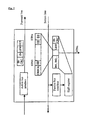
- FIG. 2 shows an exemplary simplified block view of a secure subscriber that is connected to an Interbus and is designed for evaluation of a broadcast safety field in accordance with FIG. 1 ,
- FIGS. 3 a - 3 c show a generalized schematic illustration of an Interbus ring network for illustrating data present at interfaces of individual subscribers during the data transmission of a communication cycle
- FIG. 4 a schematically shows the proportion of overhead data in the case of a telecommunication-oriented data transmission compared with
- FIG. 4 b shows a broadcast transmission
- FIGS. 3 a - 3 b show by way of example data present in each case at interfaces of the forward and return line path of individual subscribers of such a ring system during a complete Interbus communication cycle.
- the figures reveal that different sum frames ( FIG. 3 c ) are always transmitted at the incoming interfaces ( FIG. 3 a )—identified by the letters A, B and C—on the forward line path of the slave subscribers TN 1 , TN 2 and TN 3 , respectively.
- a cycle for the transmission of a data stream begins by means of the master subscriber with the transmission of the loopback word LBW, which is then followed by the current output data O 6 , O 5 , O 4 , O 3 , O 2 and O 1 for the individual slave subscribers TN 6 , TN 5 , TN 4 , TN 3 , TN 2 and TN 1 , beginning with the last subscriber, that is to say in accordance with FIG. 3 b , which illustrates the order of the memories of the individual subscribers, beginning with the subscriber TN 6 . Consequently, all the current output data of a communication cycle are present at the interface A and can thus be kept up there for evaluation by a, for example secure, monitor unit.
- the data at the interface B begins with the input data I 1 ( FIG. 3 c ) of the subscriber identified by TN 1 , since the loopback word LBW is still present at the subscriber TN 1 when the latter forwards its input data to subscriber TN 2 .
- the loopback word LBW is thus followed only by the output data O 6 , O 5 , O 4 , O 3 and O 2 of the remaining subscribers TN 6 , TN 5 , TN 4 , TN 3 and TN 2 , beginning with the data packet of the last subscriber TN 6 in the ring.
- loopback word LBW is followed only by the output data O 6 , O 5 , O 4 and O 3 of the remaining subscribers TN 6 , TN 5 , TN 4 and TN 3 and the loopback word is also additionally preceded by the input information I 2 of the upstream subscriber TN 2 .
- the information transmitted here is identical for all the subscribers in the top level remote bus of an Interbus system, the input data of which are fed directly to the master on the returning transition line. Consequently, although the subscribers TN 2 , TN 4 and TN 5 are informed about the entire returning data stream which, on the return line, contains the input data I 1 , I 2 , I 3 , I 4 , I 5 and I 6 of all the connected subscribers TN 1 , TN 2 , TN 3 , TN 4 , TN 5 and TN 6 before the loopback word LBW ( FIG. 3 c ), the subscribers TN 2 , TN 4 and TN 5 also concomitantly receive only a portion of the OUT data or output data of the master in this case.
- the subscriber TN 2 for example, never knows the OUT data for the subscriber TN 1 because they are not passed through it at all. By contrast, it receives its input I 1 immediately after the beginning of a new Interbus cycle. Only the first subscriber TN 1 and the master are able, in principle, to receive both all the output data O 6 , O 5 , O 4 , O 3 , O 2 and O 1 via the forward line (interface A) and all the input data I 1 , I 2 , I 3 , I 4 , I 5 and I 6 of the connected subscribers TN 1 , TN 2 , TN 3 , TN 4 , TN 5 and TN 6 via the return line (interface F).
- a broadcast message is now concomitantly transmitted during the transmission of output data for each communication cycle, said broadcast message enabling a flexible access for selected data embedded therein.
- the Interbus sum frame is lengthened by a broadcast message.
- the broadcast message consequently preferably comprises a safety field containing all the safety data.
- the data of a broadcast transmission as can be seen from FIG. 4 b , furthermore only has to be safeguarded once for the entire system so that the proportion of overhead data required can be significantly reduced.
- FIG. 4 a shows by way of example overhead data required for a point-to-point transmission in which subscriber-related useful data are transmitted together with respectively assigned protection data check and, in the case of a telecommunication-oriented transmission, additionally with respectively assigned address data for each subscriber individually.
- output data to be transmitted, for all the output subscribers can furthermore be output at an identical point in time throughout the system, additional data no longer having to be provided for safety-orientated subscribers.
- non-secure data including non-secure process data and/or parameter data to continue to be constructed in the known manner e.g. by PCP (peripherals communication protocol) as in the case of standard Interbus devices.
- FIG. 1 shows a ring bus with a master subscriber, a broadcast subscriber directly following the master, and further connected non-secure subscribers TN 1 , TN 2 , TN 3 , TN 5 , TN 6 , TN 7 and secure subscribers STN 4 , STN 8 and STN 9 .
- the broadcast subscriber or broadcaster arranged downstream of the controller or the master generates a protocol which transmits a safety protocol by means of a broadcast message to all of the further connected subscribers TN 1 , TN 2 , TN 3 , STN 4 , TN 5 , TN 6 , TN 7 , STN 8 and STN 9 .
- the central unit, or subscriber unit, generating the protocol may for example also be integrated in the master.
- At least all the safety-orientated useful data for the secure subscribers STNx are embedded in the safety protocol, e.g. on the basis of nibbles or service data objects (SDO), and it acquires a special safeguard CHECK, for example in the form of a so-called cyclic redundancy check (CRC).
- SDO service data objects
- CRC cyclic redundancy check
- the broadcast message is incorporated within the basic point-to-point protocol in such a way that it is situated at unambiguously defined locations at predeterminable points in time or cycle segments and an access by selected subscribers is correspondingly ensured.
- the selected subscribers require the exact assignment of the useful data to the corresponding units or subscribers, which may be done, in the case of the Interbus, by means of a special address list or physical assignment and, in other buses, e.g. by means of contained or assigned addresses.
- the broadcast message is thus expediently arranged between the loopback word LBW and the input data and the (safety-relevant) useful data are inserted as information bits in the form of input bits in the data stream beginning with the information for the first subscriber.
- the information for the subsequent subscribers directly follows.
- the safety field in accordance with FIG. 1 consequently comprises firstly the information B assigned to the broadcast subscriber followed by the information for the rest of the subscribers, that is to say followed by the information for TN 1 , TN 2 , TN 3 , STN 4 , TN 5 , TN 6 , TN 7 , STN 8 and STN 9 .
- the totality of the safety-relevant information is safeguarded once, for which purpose it is possible to employ e.g. the abovementioned CRC, or else a serial number or a combination of a plurality and, if appropriate, also different suitable measures.
- the connected, safety-orientated subscribers STNx ( FIG. 2 ) selected for accessing the safety field are designed to be able to extract the bit sequence applicable to them from the received or concomitantly read data stream, which may be effected by means of the predetermined address list in the case of the Interbus.
- each subscriber for itself simultaneously checks all the bits received by the central unit with the same measures as the central unit and compares its result with the result of the broadcast message.
- this checking may also be effected on the forward line path by means of the active bus interface by the determination of a standard Interbus CRC IB-CRC.
- the abovementioned concomitant reading may be effected in a simple manner preferably by monitoring interception on the return line, while in other bus systems the information may be read by all the subscribers at the same point in time.
- the respective safety field including the safety information (No., CRC, . . . ) carried out by the central unit can be found at a well-defined location by means of a simple shift register function in the bus system or in the sum rate.
- FIG. 2 shows in this respect the way in which the data are present in the case of an Interbus system subscriber and the safety field can be concomitantly read e.g. at an essentially arbitrary safety-orientated top level output subscriber STNx for evaluation by means of the following principle.
- the data are routed on the return line of an Interbus system from the last subscriber to the master without any changes directly through all the subscribers.
- the subscriber STNx concomitantly reads all the data by the connection of a standard protocol module and possibly supplemented by a shift register with an open output. Since, as a rule, more bits are transmitted than the protocol module and the shift register or shift registers together can acquire, the bits fall out of the subscriber unutilized until the Interbus cycle has been identified as valid. Consequently, at this point in time, only the last bits are situated in both units.
- These are firstly the standard Interbus CRC and the loopback word, depending on the size of the register. Directly after these the shift register holds the input data of the first subscriber, that is to say of the broadcast subscriber in accordance with FIG. 1 , or the data which a central unit that generates the broadcast message permits to directly follow the loopback word LBW.
- the secure broadcast information is thus preferably incorporated in the transmission protocol in the manner, otherwise of the information of a first slave subscriber.
- The, in particular secure, information intended for the selected subscriber or subscribers is in this case oriented to a broadcast sequence that is exactly adapted to the subscriber order, so that it suffices to define for the respective subscriber that location within the broadcast area at which a relevant item of information intended for it may be situated.
- each connected subscriber expediently stores the time of the last information received in a memory unit.
- the subscribers may independently initiate a defined safety-orientated reaction, and in particular effect shutdown, after a predetermined worse case time has elapsed.
- the information transmitted in the broadcast field may essentially comprise any type of information, that is to say for example individual information bits, commands, addresses, etc.
- the received information may consequently be used to initiate individually and/or in an application-specific manner safety-oriented functions of individual subscribers or of a group of subscribers, in particular output subscribers.
- the output data burden the standard data stream only at the central location, and moreover only once, it is furthermore possible, in principle, for the output subscribers also to be supplied with standard output data simultaneously.
- the respective safety-oriented units are constructed in multichannel fashion, so that specially safeguarded parameter, programming or configuration data can be transmitted via a standard PCP interface if the data are securely generated on the central unit or a remote broadcast unit and are evaluated in a safety-orientated manner on the subscriber.
- TN 3 downstream of the subscriber TN 6 , leads via TN 5 , TN 4 , TN 2 , TN 1 back to the master contains all the input or In data of the connected subscribers. The same is similarly true for the various system levels that are possible in the Interbus.
- the invention furthermore encompasses embodiments in which the “secure” broadcast field is inserted in addition to a standard or general broadcast protocol.
- a bus system such as a CAN bus, a Profibus or an Ethernet
- a broadcast safety field may be inserted into the standard broadcast information.
- the evaluation is effected analogously to the Interbus in the output modules for the output subscribers with corresponding modules, a broadcaster in this case corresponding to a secure controller which transmits the safety-relevant information to the safety input/output modules.
- the precise position of the “secure” broadcast message may expediently be effected by insertion directly after the general broadcast, in which case the order is not mandatory and may be replaced by a respective address.
- the secure broadcast message may again essentially comprise arbitrary secure information, that is to say in particular fixedly prescribed information bits or commands.
- the order may, in principle, be different in an application-specific manner or even arbitrary, provided that corresponding measures, such as e.g. a corresponding addressing, are taken to ensure that the selected subscribers, i.e. preferably the selected output subscribers or groups, can find the information respectively relevant to them.
- each connected safety-relevant subscriber may transmit a secure broadcast message which selected decentralized (output) subscribers can each evaluate for themselves.
- This property can be utilized particularly when realizing a secure information Internet traffic e.g. between inputs and outputs without a participating central unit.
Landscapes
- Engineering & Computer Science (AREA)
- Computer Networks & Wireless Communication (AREA)
- Signal Processing (AREA)
- Small-Scale Networks (AREA)
Applications Claiming Priority (3)
| Application Number | Priority Date | Filing Date | Title |
|---|---|---|---|
| DE10337699 | 2003-08-16 | ||
| DE10337699A DE10337699B4 (de) | 2003-08-16 | 2003-08-16 | Verfahren und Vorrichtung zur Übertragung von Daten über ein Busnetz unter Verwendung des Broadcast-Prinzip |
| DE10337699.2-31 | 2003-08-16 |
Publications (2)
| Publication Number | Publication Date |
|---|---|
| US20050083954A1 US20050083954A1 (en) | 2005-04-21 |
| US8705548B2 true US8705548B2 (en) | 2014-04-22 |
Family
ID=34042180
Family Applications (1)
| Application Number | Title | Priority Date | Filing Date |
|---|---|---|---|
| US10/918,970 Active 2027-10-05 US8705548B2 (en) | 2003-08-16 | 2004-08-16 | Method and apparatus for the transmission of data via a bus network using the broadcast principle |
Country Status (5)
| Country | Link |
|---|---|
| US (1) | US8705548B2 (de) |
| EP (1) | EP1509005B1 (de) |
| JP (1) | JP4711386B2 (de) |
| DE (1) | DE10337699B4 (de) |
| ES (1) | ES2546385T3 (de) |
Cited By (1)
| Publication number | Priority date | Publication date | Assignee | Title |
|---|---|---|---|---|
| US9960981B2 (en) * | 2015-10-08 | 2018-05-01 | Sony Corporation | Communication device, communication method, program, and communication system |
Families Citing this family (13)
| Publication number | Priority date | Publication date | Assignee | Title |
|---|---|---|---|---|
| AT500350B8 (de) * | 2003-10-03 | 2007-02-15 | Bernecker & Rainer Ind Elektro | Anlage zum übertragen von daten in einem seriellen, bidirektionalen bus |
| DE102005060085B9 (de) | 2005-12-15 | 2010-09-30 | Beckhoff Automation Gmbh | Verfahren, Kommunikationsnetzwerk und Steuereinheit zum zyklischen Übertragen von Daten |
| DE102006006509A1 (de) | 2006-02-10 | 2007-08-16 | Robert Bosch Gmbh | Verfahren zum Betreiben eines Netzwerkes |
| DE102007004044B4 (de) * | 2007-01-22 | 2009-09-10 | Phoenix Contact Gmbh & Co. Kg | Verfahren und Anlage zur optimierten Übertragung von Daten zwischen einer Steuereinrichtung und mehreren Feldgeräten |
| DE102008018633B4 (de) * | 2008-04-11 | 2013-10-10 | Phoenix Contact Gmbh & Co. Kg | Verfahren, Buskomponenten und Steuerungssystem zur Ethernet-basierten Steuerung eines Automatisierungssystems |
| US7881330B2 (en) * | 2008-10-28 | 2011-02-01 | Plx Technology, Inc. | Controlling activation of electronic circuitry of data ports of a communication system |
| US8018934B2 (en) * | 2009-03-20 | 2011-09-13 | Cisco Technology, Inc. | Switched unicast in an internet protocol television environment |
| US9507839B2 (en) * | 2010-09-23 | 2016-11-29 | Sap Se | Method for determining a supported connectivity between applications |
| JP6390113B2 (ja) * | 2014-02-14 | 2018-09-19 | オムロン株式会社 | 制御システム、開発支援装置、制御装置、および制御方法 |
| DE102017208818A1 (de) * | 2017-05-24 | 2018-11-29 | Wago Verwaltungsgesellschaft Mbh | Initialisierung von Datenbusteilnehmern |
| DE102017119578A1 (de) | 2017-08-25 | 2019-02-28 | Phoenix Contact Gmbh & Co. Kg | Verfahren zur Übertragung von Daten zwischen einer zentralen Steuereinrichtung und einer Mehrzahl dezentraler Geräte und entsprechende Vorrichtungen |
| DE102022120561A1 (de) | 2022-08-16 | 2024-02-22 | Turck Holding Gmbh | MODULBUS-Segment und Verfahren zur Automation einer Behandlungsanlage |
| DE102022120563A1 (de) | 2022-08-16 | 2024-02-22 | Turck Holding Gmbh | MODULBUS-System und Verfahren zur Automation einer Behandlungsanlage |
Citations (22)
| Publication number | Priority date | Publication date | Assignee | Title |
|---|---|---|---|---|
| DE4213792A1 (de) * | 1992-04-27 | 1993-10-28 | Siemens Ag | Verfahren zum Betreiben eines Datenübertragungssystems |
| EP1050826A1 (de) * | 1999-05-05 | 2000-11-08 | Motorola, Inc. | Betriebsverfahren eines Kommunikationssystems auf einem seriellen Bus |
| DE19927635A1 (de) | 1999-06-17 | 2001-01-04 | Phoenix Contact Gmbh & Co | Sicherheitsbezogenes Automatisierungsbussystem |
| EP1075110A2 (de) | 1999-07-28 | 2001-02-07 | PHOENIX CONTACT GmbH & Co. | Kombiniertes Master/Slave-Producer/Consumer-Kommunikations-verfahren für ein Netzwerk |
| US6215816B1 (en) * | 1997-03-04 | 2001-04-10 | Texas Instruments Incorporated | Physical layer interface device |
| US6282669B1 (en) * | 1997-01-16 | 2001-08-28 | Yamatake-Honeywell Co., Ltd. | Ethernet communication redundancy method |
| US20010024445A1 (en) | 2000-02-23 | 2001-09-27 | Takuro Noda | Communication system, communication device and communication method |
| US6434117B1 (en) | 1998-03-06 | 2002-08-13 | Nec Corporation | IEEE-1394 serial bus network capable of multicast communication |
| US20020126661A1 (en) * | 2001-03-12 | 2002-09-12 | Ngai Henry P. | Dual-loop bus-based network switch using distance-value or bit-mask |
| US20030002482A1 (en) * | 1995-10-05 | 2003-01-02 | Kubler Joseph J. | Hierarchical data collection network supporting packetized voice communications among wireless terminals and telephones |
| US20030031209A1 (en) * | 2001-07-09 | 2003-02-13 | Zvi Regev | High speed ring/bus |
| DE10237351A1 (de) | 2001-09-26 | 2003-04-24 | Siemens Ag | Verfahren zum Betrieb eines Koppelknotens in einem Datennetz |
| DE10155975A1 (de) | 2001-11-14 | 2003-05-28 | Conti Temic Microelectronic | Verfahren zur Überprüfung der fehlerfreien Funktion von Modulen in einem Bussystem mit einer Zentraleinheit sowie entsprechende Module und Zentraleinheit |
| US20040098514A1 (en) * | 2000-09-29 | 2004-05-20 | Armin Schuster | Method and device for establishing the network topology of a bus system |
| US20040267997A1 (en) * | 1999-09-07 | 2004-12-30 | Grzybowski Peter W | Method and apparatus for a wearable computer |
| US7072346B2 (en) * | 2000-11-27 | 2006-07-04 | Fujitsu Limited | Network and edge router |
| US7072803B2 (en) * | 2002-03-15 | 2006-07-04 | Airbus France | Device and process for acquisition of measurements using a digital communication bus, particularly used during aircraft tests |
| US7095752B2 (en) * | 2001-02-28 | 2006-08-22 | Pmc-Sierra, Inc. | On-chip inter-subsystem communication including concurrent data traffic routing |
| US7136953B1 (en) * | 2003-05-07 | 2006-11-14 | Nvidia Corporation | Apparatus, system, and method for bus link width optimization |
| US7187655B1 (en) * | 1999-08-31 | 2007-03-06 | Sony Corporation | Information communication method and apparatus |
| US7206881B2 (en) * | 2002-09-16 | 2007-04-17 | Telefonaktiebolaget Lm Ericsson (Publ) | Arrangement and method for controlling dataflow on a data bus |
| US7245631B2 (en) * | 2001-04-27 | 2007-07-17 | Mitsubishi Jidosha Kogyo Kabushiki Kaisha | Multiplex communication apparatus for vehicle |
-
2003
- 2003-08-16 DE DE10337699A patent/DE10337699B4/de not_active Expired - Lifetime
-
2004
- 2004-07-17 EP EP04016902.1A patent/EP1509005B1/de not_active Not-in-force
- 2004-07-17 ES ES04016902.1T patent/ES2546385T3/es active Active
- 2004-08-16 JP JP2004236352A patent/JP4711386B2/ja active Active
- 2004-08-16 US US10/918,970 patent/US8705548B2/en active Active
Patent Citations (24)
| Publication number | Priority date | Publication date | Assignee | Title |
|---|---|---|---|---|
| DE4213792A1 (de) * | 1992-04-27 | 1993-10-28 | Siemens Ag | Verfahren zum Betreiben eines Datenübertragungssystems |
| US20030002482A1 (en) * | 1995-10-05 | 2003-01-02 | Kubler Joseph J. | Hierarchical data collection network supporting packetized voice communications among wireless terminals and telephones |
| US6282669B1 (en) * | 1997-01-16 | 2001-08-28 | Yamatake-Honeywell Co., Ltd. | Ethernet communication redundancy method |
| US6215816B1 (en) * | 1997-03-04 | 2001-04-10 | Texas Instruments Incorporated | Physical layer interface device |
| US6434117B1 (en) | 1998-03-06 | 2002-08-13 | Nec Corporation | IEEE-1394 serial bus network capable of multicast communication |
| EP1050826A1 (de) * | 1999-05-05 | 2000-11-08 | Motorola, Inc. | Betriebsverfahren eines Kommunikationssystems auf einem seriellen Bus |
| DE19927635A1 (de) | 1999-06-17 | 2001-01-04 | Phoenix Contact Gmbh & Co | Sicherheitsbezogenes Automatisierungsbussystem |
| US6957115B1 (en) * | 1999-06-17 | 2005-10-18 | Phoenix Contact Gmbh & Co. | Security-related bus automation system |
| EP1075110A2 (de) | 1999-07-28 | 2001-02-07 | PHOENIX CONTACT GmbH & Co. | Kombiniertes Master/Slave-Producer/Consumer-Kommunikations-verfahren für ein Netzwerk |
| DE19935490A1 (de) | 1999-07-28 | 2001-02-08 | Phoenix Contact Gmbh & Co | Kombiniertes Master/Slave-Producer/Consumer-Kommunikationsverfahren für ein Netzwerk |
| US7187655B1 (en) * | 1999-08-31 | 2007-03-06 | Sony Corporation | Information communication method and apparatus |
| US20040267997A1 (en) * | 1999-09-07 | 2004-12-30 | Grzybowski Peter W | Method and apparatus for a wearable computer |
| US20010024445A1 (en) | 2000-02-23 | 2001-09-27 | Takuro Noda | Communication system, communication device and communication method |
| US20040098514A1 (en) * | 2000-09-29 | 2004-05-20 | Armin Schuster | Method and device for establishing the network topology of a bus system |
| US7072346B2 (en) * | 2000-11-27 | 2006-07-04 | Fujitsu Limited | Network and edge router |
| US7095752B2 (en) * | 2001-02-28 | 2006-08-22 | Pmc-Sierra, Inc. | On-chip inter-subsystem communication including concurrent data traffic routing |
| US20020126661A1 (en) * | 2001-03-12 | 2002-09-12 | Ngai Henry P. | Dual-loop bus-based network switch using distance-value or bit-mask |
| US7245631B2 (en) * | 2001-04-27 | 2007-07-17 | Mitsubishi Jidosha Kogyo Kabushiki Kaisha | Multiplex communication apparatus for vehicle |
| US20030031209A1 (en) * | 2001-07-09 | 2003-02-13 | Zvi Regev | High speed ring/bus |
| DE10237351A1 (de) | 2001-09-26 | 2003-04-24 | Siemens Ag | Verfahren zum Betrieb eines Koppelknotens in einem Datennetz |
| DE10155975A1 (de) | 2001-11-14 | 2003-05-28 | Conti Temic Microelectronic | Verfahren zur Überprüfung der fehlerfreien Funktion von Modulen in einem Bussystem mit einer Zentraleinheit sowie entsprechende Module und Zentraleinheit |
| US7072803B2 (en) * | 2002-03-15 | 2006-07-04 | Airbus France | Device and process for acquisition of measurements using a digital communication bus, particularly used during aircraft tests |
| US7206881B2 (en) * | 2002-09-16 | 2007-04-17 | Telefonaktiebolaget Lm Ericsson (Publ) | Arrangement and method for controlling dataflow on a data bus |
| US7136953B1 (en) * | 2003-05-07 | 2006-11-14 | Nvidia Corporation | Apparatus, system, and method for bus link width optimization |
Non-Patent Citations (3)
| Title |
|---|
| European Search Report dated Nov. 15, 2004 for corresponding European Patent Application No. 04016902.1. |
| Office Action corresponding to Japanese Patent Application No. 2004-236352 dated May 13, 2008. |
| Office action dated Jul. 5, 2010 for corresponding Japanese Patent Application No. 2004-236352. |
Cited By (3)
| Publication number | Priority date | Publication date | Assignee | Title |
|---|---|---|---|---|
| US9960981B2 (en) * | 2015-10-08 | 2018-05-01 | Sony Corporation | Communication device, communication method, program, and communication system |
| US10116542B2 (en) | 2015-10-08 | 2018-10-30 | Sony Corporation | Communication device, communication method, program, and communication system |
| TWI730993B (zh) * | 2015-10-08 | 2021-06-21 | 日商新力股份有限公司 | 第1通信裝置、通信方法、及通信系統 |
Also Published As
| Publication number | Publication date |
|---|---|
| EP1509005B1 (de) | 2015-07-01 |
| DE10337699B4 (de) | 2006-01-12 |
| US20050083954A1 (en) | 2005-04-21 |
| ES2546385T3 (es) | 2015-09-23 |
| EP1509005A1 (de) | 2005-02-23 |
| JP2005065296A (ja) | 2005-03-10 |
| JP4711386B2 (ja) | 2011-06-29 |
| DE10337699A1 (de) | 2005-03-17 |
Similar Documents
| Publication | Publication Date | Title |
|---|---|---|
| US8705548B2 (en) | Method and apparatus for the transmission of data via a bus network using the broadcast principle | |
| EP2064841B1 (de) | Intelligenter sternkoppler für ein zeitgesteuertes kommunikationsprotokoll und verfahren zur kommunikation zwischen knoten innerhalb eines netzwerks über ein zeitgesteuertes protokoll | |
| US8015324B2 (en) | Method for data transmission | |
| CN101690020B (zh) | 确定性通信系统 | |
| US5748613A (en) | Communication pacing method | |
| CN1993687B (zh) | 用于控制数据访问的消息管理器和方法以及通信组件 | |
| JP4542733B2 (ja) | フィールドバスに接続されたステーションのコンフィギュレーション実施方法およびステーション | |
| US20060092858A1 (en) | Method for transmitting data in a communication system | |
| US8230146B2 (en) | Communication method and master-slave system for a field bus configured according to the AS-interface standard | |
| US9960997B2 (en) | Method and system for data aggregation in an industrial communication protocol | |
| US10523462B2 (en) | Communication network for transmission of messages | |
| US4769839A (en) | Method and device for the transfer of data in a data loop | |
| JP2008509583A (ja) | 通信モジュールのメッセージメモリのデータへアクセスする方法および装置 | |
| US11483240B2 (en) | Master-slave bus system and method for operating a bus system | |
| JP2006529072A (ja) | 二重チャネルネットワークの同期化に関する時間トリガ型通信システムおよび方法 | |
| US8320262B2 (en) | Bus system and method and device for transmitting communications on a bus system | |
| EP2260599A1 (de) | Hochpräzise synchronisationsnetzwerkvorrichtung, netzwerksystem und rahmenübertragungsverfahren | |
| US20020141411A1 (en) | Apparatus for line-concentrating and distributing PPP frame data | |
| JPWO2007096987A1 (ja) | エラー制御装置 | |
| US11296903B2 (en) | Master of a bus system | |
| US11184194B2 (en) | Distributed processing of process data | |
| FI61260C (fi) | Foerfarande i ett dataoeverfoeringssystem foer mottagning och saendning av datastroemmar i multiplexkanaler | |
| JP2005522942A (ja) | データ部分の補填方法,その装置及びバスシステム | |
| JP2005341492A (ja) | ゲートウェイ装置および方法 | |
| JP2001086129A (ja) | 制御データ伝送装置 |
Legal Events
| Date | Code | Title | Description |
|---|---|---|---|
| AS | Assignment |
Owner name: PHOENIX CONTACT GMBH & CO. KG, GERMANY Free format text: ASSIGNMENT OF ASSIGNORS INTEREST;ASSIGNOR:MEYER-GRAFE, KARSTEN;REEL/FRAME:016078/0326 Effective date: 20041118 |
|
| STCF | Information on status: patent grant |
Free format text: PATENTED CASE |
|
| MAFP | Maintenance fee payment |
Free format text: PAYMENT OF MAINTENANCE FEE, 4TH YEAR, LARGE ENTITY (ORIGINAL EVENT CODE: M1551) Year of fee payment: 4 |
|
| MAFP | Maintenance fee payment |
Free format text: PAYMENT OF MAINTENANCE FEE, 8TH YEAR, LARGE ENTITY (ORIGINAL EVENT CODE: M1552); ENTITY STATUS OF PATENT OWNER: LARGE ENTITY Year of fee payment: 8 |