US8663095B2 - Marker and guide sheath system for endoscopic treatment tool - Google Patents
Marker and guide sheath system for endoscopic treatment tool Download PDFInfo
- Publication number
- US8663095B2 US8663095B2 US12/146,216 US14621608A US8663095B2 US 8663095 B2 US8663095 B2 US 8663095B2 US 14621608 A US14621608 A US 14621608A US 8663095 B2 US8663095 B2 US 8663095B2
- Authority
- US
- United States
- Prior art keywords
- treatment tool
- endoscopic treatment
- guide sheath
- marker
- insertion hole
- Prior art date
- Legal status (The legal status is an assumption and is not a legal conclusion. Google has not performed a legal analysis and makes no representation as to the accuracy of the status listed.)
- Active, expires
Links
Images


Classifications
-
- A—HUMAN NECESSITIES
- A61—MEDICAL OR VETERINARY SCIENCE; HYGIENE
- A61B—DIAGNOSIS; SURGERY; IDENTIFICATION
- A61B10/00—Instruments for taking body samples for diagnostic purposes; Other methods or instruments for diagnosis, e.g. for vaccination diagnosis, sex determination or ovulation-period determination; Throat striking implements
- A61B10/02—Instruments for taking cell samples or for biopsy
- A61B10/04—Endoscopic instruments, e.g. catheter-type instruments
-
- A—HUMAN NECESSITIES
- A61—MEDICAL OR VETERINARY SCIENCE; HYGIENE
- A61B—DIAGNOSIS; SURGERY; IDENTIFICATION
- A61B90/00—Instruments, implements or accessories specially adapted for surgery or diagnosis and not covered by any of the groups A61B1/00 - A61B50/00, e.g. for luxation treatment or for protecting wound edges
- A61B90/39—Markers, e.g. radio-opaque or breast lesions markers
-
- A—HUMAN NECESSITIES
- A61—MEDICAL OR VETERINARY SCIENCE; HYGIENE
- A61B—DIAGNOSIS; SURGERY; IDENTIFICATION
- A61B10/00—Instruments for taking body samples for diagnostic purposes; Other methods or instruments for diagnosis, e.g. for vaccination diagnosis, sex determination or ovulation-period determination; Throat striking implements
- A61B10/02—Instruments for taking cell samples or for biopsy
- A61B10/06—Biopsy forceps, e.g. with cup-shaped jaws
-
- A—HUMAN NECESSITIES
- A61—MEDICAL OR VETERINARY SCIENCE; HYGIENE
- A61B—DIAGNOSIS; SURGERY; IDENTIFICATION
- A61B90/00—Instruments, implements or accessories specially adapted for surgery or diagnosis and not covered by any of the groups A61B1/00 - A61B50/00, e.g. for luxation treatment or for protecting wound edges
- A61B90/03—Automatic limiting or abutting means, e.g. for safety
- A61B2090/033—Abutting means, stops, e.g. abutting on tissue or skin
- A61B2090/034—Abutting means, stops, e.g. abutting on tissue or skin abutting on parts of the device itself
-
- A—HUMAN NECESSITIES
- A61—MEDICAL OR VETERINARY SCIENCE; HYGIENE
- A61B—DIAGNOSIS; SURGERY; IDENTIFICATION
- A61B90/00—Instruments, implements or accessories specially adapted for surgery or diagnosis and not covered by any of the groups A61B1/00 - A61B50/00, e.g. for luxation treatment or for protecting wound edges
- A61B90/06—Measuring instruments not otherwise provided for
- A61B2090/061—Measuring instruments not otherwise provided for for measuring dimensions, e.g. length
-
- A—HUMAN NECESSITIES
- A61—MEDICAL OR VETERINARY SCIENCE; HYGIENE
- A61B—DIAGNOSIS; SURGERY; IDENTIFICATION
- A61B90/00—Instruments, implements or accessories specially adapted for surgery or diagnosis and not covered by any of the groups A61B1/00 - A61B50/00, e.g. for luxation treatment or for protecting wound edges
- A61B90/08—Accessories or related features not otherwise provided for
- A61B2090/0807—Indication means
- A61B2090/0811—Indication means for the position of a particular part of an instrument with respect to the rest of the instrument, e.g. position of the anvil of a stapling instrument
Definitions
- the present invention relates to a marker and a guide sheath system to be attached to an endoscopic treatment tool.
- bronchiole diameter is so small that a usual endoscope tip cannot reach the target site.
- the bronchiole may be branched several times from the tip of the endoscope to the target site, and thus it is difficult to repeatedly make the treatment tool reach the target site after taking biopsy tissue samples at that site.
- Japanese Unexamined Patent Application, First Publication No. 2004-154485 discloses a method for biopsy in which a guide sheath having a diameter smaller than that of the endoscope is inserted in a channel of the endoscope, projected from an endoscope tip to be held near a target site, and a treatment tool is inserted in the guide sheath for performing biopsy.
- a targeted lesion is often very small. Even if a lesion is detected by using a ultrasonic probe or other instruments, it is difficult for an operator to determine how far the treatment tool such as forceps is to be advanced for performing biopsy after the removal of the ultrasonic probe. Merely several millimeters of misalignment may cause the treatment tool to miss the target site. A problem has currently arisen that it is only after the inspection is completed that the operator finds out whether or not proper tissue samples were taken. In addition, usually the tissue samples are taken five or six times at a site, the above-mentioned problem may occur more often. In fact, accuracy in such a biopsy is currently insufficient.
- the tip position of the treatment tool is observed at all times by X-ray radioscopy, the above problems may be avoided.
- the X-ray radioscopy may expose the patient to radiation in a large amount. Thus, it is a seriously invasive procedure for just an inspection.
- an object of the invention is to provide a marker and a guide sheath system to be attached to an endoscopic treatment tool for precisely directing a tip of the treatment tool to a target site with no additional physical burden to the patient.
- the invention is a marker used in an endoscopic treatment tool to be inserted in a guide sheath.
- the marker includes: a body; and a fixing portion for removably fixing the body to a middle section of the endoscopic treatment tool, wherein the distance between the body and a tip of the endoscopic treatment tool can be determined freely.
- an operator can control the endoscopic treatment tool such that a desired length of the marker inserted in the guide sheath is projected from the guide sheath tip by fixing the marker on the fixing portion at a desired position of the middle section of the endoscopic treatment tool.
- the body is formed of an elastic material and includes an insertion hole in which the endoscopic treatment tool is inserted; and the fixing portion is defined by an inner wall of the insertion hole and fixes the body to be slidable in an axial direction of the endoscopic treatment tool due to frictional force generated between the endoscopic treatment tool and the inner wall of the insertion hole.
- the marker used in the endoscopic treatment tool of the invention further includes an abutting portion which abuts a base end of the guide sheath, wherein the abutting portion may be made to abut the base end of the guide sheath to allow the tip of the endoscopic treatment tool to project from the tip of the guide sheath by a predetermined amount.
- the marker used in the endoscopic treatment tool of the invention further includes an engaging portion to be engaged with the base end of the guide sheath, wherein the engaging portion may be made to be engaged with the base end of the guide sheath to allow the tip of the endoscopic treatment tool to project from the tip of the guide sheath by a predetermined amount.
- a guide sheath system for an endoscopic treatment tool includes: a marker used in an endoscopic treatment tool according to the invention; and a guide sheath which includes at a base end thereof an engaging member which is engaged with the engaging portion.
- the tip of the endoscopic treatment tool can be projected precisely with the marker used in the endoscopic treatment tool engaged into the engaging member provided at the base end of the guide sheath.
- the engaging portion of the marker of the endoscopic treatment tool may include a circumferential engaging groove formed in a radial direction outside of the insertion hole, and when the engaging member advances in the engaging groove, the guide sheath and the marker used in the endoscopic treatment tool may engage each other.
- the marker used in the endoscopic treatment tool can be securely fixed to the guide sheath.
- a wall surface of the engaging groove at the side of the insertion hole may be formed such that the engaging groove has a radial direction width which becomes gradually smaller along an axial direction of the insertion hole from an end at which the engaging member enters; an inner surface of the engaging member may be formed such that a wall thickness of the engaging member becomes thicker in an axial direction of the engaging member from an end at which the engaging member enters the engaging groove; a taper angle of the inner surface of the engaging member may be larger than that of the wall surface at the side of the insertion hole of the engaging groove; when the engaging member advances in the engaging groove, the wall surface at the side of the insertion hole of the engaging groove may be pressed against the insertion hole and the body may be fixed to the endoscopic treatment tool.
- the guide sheath system can be obtained that firmly fixes the endoscopic treatment tool while sliding resistance during adjustment of the fixing position is small.
- the tip of the endoscopic treatment tool can be precisely positioned at the target site with no additional physical burden to the patient.
- FIG. 1 is a perspective view of a marker used in an endoscopic treatment tool according to an embodiment of the invention.
- FIG. 2 is a right side view, partially shown in cross-section, of the marker used in the endoscopic treatment tool.
- FIG. 3 is a front view of the marker used in the endoscopic treatment tool.
- FIG. 4 is a partial cross-sectional view of a guide sheath used with the endoscopic treatment tool.
- FIG. 5 is a flow chart illustrating the procedure of lung biopsy using the marker used in the endoscopic treatment tool.
- FIG. 6 is a view illustrating a state in which the endoscope is moved near the target site.
- FIG. 7 is a view illustrating a state in which an ultrasonic probe is projected from the endoscope.
- FIG. 8 is a view illustrating a state in which an image of the target site is obtained with the ultrasonic probe.
- FIG. 9 is a view illustrating a state in which the guide sheath is held at the target site.
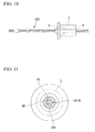
- FIG. 10 is a view illustrating a state in which the marker used in the endoscopic treatment tool is attached to a biopsy cup.
- FIG. 11 is a front view of the marker used in the endoscopic treatment tool with the biopsy cup attached thereto.
- FIG. 12 is a view illustrating a state in which the marker used in the endoscopic treatment tool with the biopsy cup attached thereto is inserted in the guide sheath.
- FIG. 13 is a front view illustrating a state in which the marker used in the endoscopic treatment tool with the biopsy cup attached thereto is inserted in the guide sheath.
- FIG. 14 is a view illustrating a state in which tissue of the target site is taken using the biopsy cup.
- marker used in the endoscopic treatment tool (hereinafter, referred to as “marker”) according to an embodiment of the invention will be described.
- FIG. 1 is a perspective view of a marker 1 .
- the marker 1 is formed of an elastic material such as silicone rubber.
- the marker 1 includes a substantially cylindrical body 2 and a engaging portion 3 provided at a front end of the body 2 .
- FIG. 2 is a right side view, partially shown in cross-section, of the marker 1 .
- the marker 1 includes an insertion hole 4 along its central axis in which an endoscopic treatment tool is inserted.
- the insertion hole 4 includes a tip section 4 A at the side of engaging portion 3 , an inserting section 4 C at the side of an opposite rear end, and a middle section 4 B between the tip section 4 A and the inserting section 4 C.
- the tip section 4 A is square-sectioned and functions as a fixing portion for fixing the body 2 to an intended position of the middle section of the endoscopic treatment tool due to frictional force generated at the contact face of the tip section 4 A and the external surface of the endoscopic treatment tool as described later.
- the middle section 4 B is circular-sectioned and has a diameter larger than the maximum inner diameter (i.e., the diagonal diameter in the cross-section) of the tip section 4 A. Thus, the middle section 4 B does not come in direct contact with an external surface of the endoscope treatment tool.
- the inserting section 4 C is also circular-sectioned and has a diameter that is substantially the same as that of the middle section 4 B at the side of the middle section 4 B and gradually expands toward the rear end. Namely, the inserting section 4 C is formed in a tapered shape such that the endoscopic treatment tool may be easily inserted from the expanded rear end of the insertion hole 4 .
- the marker 1 is removably attached to the endoscopic treatment tool. In particular, after the endoscopic treatment tool is inserted from the inserting section 4 C and the marker 1 is attached, the endoscopic treatment tool can be removed.
- the engaging portion 3 includes an annular engaging groove 5 provided in a circumferential direction thereof on a radial direction outside of the insertion hole 4 , and a flange 6 circumferentially projecting from the radial direction outside of the engaging groove 5 .
- the engaging groove 5 is provided between the external surface of the tip section 4 A of the insertion hole 4 and the body 2 concentrically with the insertion hole 4 .
- a guide sheath is engaged in the engaging groove 5 as described later.
- the engaging groove 5 includes a first surface 5 A at the side of the flange 6 formed substantially parallel with the axial direction of the marker 1 , and a second surface (wall surface) 5 B at the side of the insertion hole 4 formed such that a radial direction width W 1 of the engaging groove 5 at the front end is slightly larger than a radial direction width W 2 at the rear end. That is, the engaging groove 5 is tapered such that the radial direction width thereof becomes smaller toward the axial direction of the insertion hole 4 .
- FIG. 4 is a partial cross-sectional view of a guide sheath 7 used with the marker 1 .
- the guide sheath 7 includes a tubular, flexible sheath body 8 made of, for example, resin, and a stick (engaging member) 9 attached to a base end of the sheath body 8 .
- a tubular indexing member 10 made of stainless steel or the like is thermoformed at an inner surface of the sheath body 8 near the tip thereof. With the X-ray radioscopy, the indexing member 10 is an indication of the tip position of the sheath body 8 .
- a base end of the sheath body 8 is press-fit at the tip of the stick 9 and is fixed by a coil 11 from the outside.
- the stick 9 is a tubular member made of resin or the like, and includes a through hole 12 inside thereof.
- An endoscopic treatment tool is inserted in the through hole 12 .
- the through hole 12 is circular-sectioned and includes a first section 12 A with a constant diameter and a second section 12 B with a diameter gradually expanding toward the rear end.
- the inner surface of the second section 12 B is formed such that the wall surface of the stick 9 becomes thicker in the axial direction of the stick 9 from the rear end where the stick 9 enters the engaging groove 5 of the marker 1 .
- the taper angle of the inner surface of the second section 12 B is larger than that of the second surface 5 B of the engaging groove 5 of the marker 1 .
- FIG. 5 is a flow chart illustrating a procedure of lung biopsy using an endoscopic treatment tool performing with the marker 1 and the guide sheath 7 .
- step S 1 shown in FIG. 5 the guide sheath 7 is moved to the target site where tissue samples are to be taken.
- the endoscope is advanced within a bronchus while the position of the target site is observed through X-ray radioscopy images.
- FIG. 6 illustrates a state in which an endoscope 100 is advanced to the vicinity of a target site R. Since the diameter of a bronchiole 101 in which the target site R exists is smaller than that of the endoscope 100 , the endoscope 100 cannot be advanced further toward the target site R.
- an ultrasonic probe 102 placed in the guide sheath 7 is inserted together with the guide sheath 7 from an opening for forceps (not shown) of the endoscope 100 and is projected from the tip of the endoscope 100 as shown in FIG. 7 . Since the diameters of the sheath body 8 and the ultrasonic probe 102 of the guide sheath 7 are smaller than that of the endoscope 100 , the guide sheath 7 can reach the target site R through the bronchiole 101 .
- the sheath body 8 itself is stopped at a position considered near but not touching the target site R, and the ultrasonic probe 102 is moved ahead to a position beyond the target site R. Then, the ultrasonic probe 102 is slowly pulled back in the direction of an arrow in FIG. 8 .
- Images of the tissue around the ultrasonic probe 102 are displayed on unillustrated test equipment through the ultrasonic wave emitted from the ultrasonic probe 102 .
- the operator can confirm whether the ultrasonic probe 102 has reached the target site R.
- step S 2 the sheath body 8 is advanced to the vicinity of the target site R along the ultrasonic probe 102 as shown in FIG. 9 .
- the position of the tip of the sheath body 8 is confirmed by the indexing member 10 (not shown).
- the position of the ultrasonic probe 102 projected from the rear end of the stick 9 of the guide sheath 7 is marked. Then, only the ultrasonic probe 102 is removed from the guide sheath 7 and the guide sheath 7 is held there.
- a known biopsy cup (endoscopic treatment tool) 103 is inserted in the insertion hole 4 from the rear end of the marker 1 , and the marker 1 is fixed to the biopsy cup 103 as shown in FIG. 10 .
- the marker 1 is then slid to a position where the distance between the rear end of the engaging groove 5 and the tip of the biopsy cup equals the distance between the tip of the ultrasonic probe 102 and the marking taken in step S 2 .
- biopsy cup 103 instead of the biopsy cup 103 , other treatment tools such as a biopsy brush may alternatively be used.
- other treatment tools such as a biopsy brush may alternatively be used.
- the tip section 4 A of the insertion hole 4 which functions as the fixing portion is square-sectioned, the tip section 4 A is made to contact the biopsy cup 103 at four sides 4 D as shown in FIG. 11 .
- the frictional force generated between the tip section 4 A and the biopsy cups 103 is small, whereby the marker 1 can be slid smoothly for positional alignment.
- the marker 1 is formed of a transparent material, the rear end of the engaging groove 5 is more clearly visible, and positioning of the marker 1 can be made more precisely.
- step S 4 the biopsy cup 103 to which the marker 1 is attached is inserted in the guide sheath 7 from the base end of the stick 9 . Then, as shown in the dotted line in FIG. 12 , the rear end of the stick 9 is made to advance into the engaging groove 5 of the marker 1 , and the marker 1 is engaged in the guide sheath 7 .
- the taper angle of the inner surface of the second section 12 B of the through hole 12 formed in the stick 9 is larger than that of the second surface 5 B of the engaging groove 5 of the marker 1 , the second surface 5 B of the engaging groove 5 is pressed against the insertion hole 4 as the stick 9 advances in the engaging groove 5 .
- the tip section 4 A of the insertion hole 4 nips the biopsy cup 103 with far stronger force than before engagement, while keeping point contact with the biopsy cup 103 .
- the marker 1 is securely fixed to the biopsy cup 103 , and forward and backward movement of the biopsy cup 103 within the guide sheath 7 is prevented.
- the biopsy cup 103 is projected only the same distance as that of the ultrasonic probe 102 in step S 2 from the tip of the sheath body 8 , and the tip of the biopsy cup 103 reliably reaches the target site R as shown in FIG. 14 .
- step S 5 the biopsy cup 103 is operated to take tissue samples at the target site R. After taking the tissue samples, the biopsy cup 103 is removed and the tissue samples are collected. Taking tissue samples in step S 5 may be repeated several times when needed. It is also possible to estimate the size (i.e., the length along the direction in which the bronchiole 101 extends) of the target site R by repeating taking tissue samples several times with the position of the marker 1 fine-controlled and moving the tip of the biopsy cut 103 forward and backward in order to specify the position at which no more tissue sample can be taken.
- the size i.e., the length along the direction in which the bronchiole 101 extends
- a projecting length of the biopsy cup 103 from the guide sheath 7 may be determined in advance, the marker 1 may be attached at a predetermined position on the biopsy cup 103 so that the biopsy cup 103 projects at the predetermined length, and then the guide sheath 7 may be disposed such that the distance between the tip of the ultrasonic probe 102 and the tip of the guide sheath 7 equals the above predetermined length while observing via X-ray radioscopy.
- step S 1 instead of providing the ultrasonic probe 102 , the biopsy cup 103 inserted in the guide sheath may be advanced to the target site R.
- the guide sheath 7 alone may be advanced to the target site.
- X-ray radioscopy, a ultrasonic image or an endoscope image may be suitably selected for guiding instruments to the target site R.
- the marker 1 is attached to the biopsy cup 103 before the biopsy cup 103 is inserted in the guide sheath 7 , but the marker 1 is not necessarily engaged and fixed to the stick 9 immediately after the ultrasonic probe 102 is removed.
- the marker 1 may be engaged with the stick 9 when the tip of the biopsy cup 103 is positioned under X-ray radioscopy, thereby positioning and engagement may occur at the same time.
- the positional relationship between the biopsy cup 103 and the guide sheath 7 is fixed when the engaging groove 5 of the engaging portion 3 engages the guide sheath 7 .
- the tip of the biopsy cup 103 can be projected precisely by the predetermined amount.
- the tip of the biopsy cup 103 can reliably reach the target site R, thereby performing a precise biopsy.
- the marker 1 is slidably fixed to the biopsy cup 103 in the axial direction thereof due to frictional force between the inner surface of the tip section 4 A of the insertion hole 4 and the outer surface of the biopsy cup 103 .
- the projecting length of the biopsy cup 103 from the guide sheath 7 can be controlled as intended by changing the position at which the marker 1 is fixed to the biopsy cup 103 .
- the marker 1 and the biopsy cup 103 are in contact with each other not in the entire inner surface of the insertion hole 4 , but only in the inner surface of the tip section 4 A. Further, since the tip section 4 A is square-sectioned as described above, the tip section 4 A is made to point contact with the biopsy cup 103 only at four sides 4 D. Thus, since the marker 1 is structured to have a smaller contact area with the biopsy cup 103 to be attached to, the frictional force generated between the marker 1 and the biopsy cups 103 in the axial direction is small, whereby the marker 1 can be slid smoothly for positional alignment.
- the marker 1 is engaged with the stick 9 of the guide sheath 7 such that, as the stick 9 advances in the engaging groove 5 , the second surface 5 B of the engaging groove 5 is pressed against the insertion hole 4 due to a difference in taper angles as described above.
- the marker 1 is firmly fixed to the biopsy cup 103 , and the positional relationship with the guide sheath 7 in operation including taking tissue samples is reliably maintained. In this manner, a marker which slides smoothly for positional alignment and is firmly fixed for engagement can be obtained.
- the flange 6 is provided in the engaging portion 3 , even if the external surface of the body 2 is drawn toward the rear end side due to deformation at the time of engagement with the stick 9 , the flange 6 moves toward the radial direction inner side, the movement of the entire external surface of the body 2 can be prevented. Therefore, a marker with holding performance which is not easily decline during engagement can be obtained.
- the marker 1 includes the engaging portion 3 and is engaged with the base end of the guide sheath 7
- an abutting portion may be provided instead of the engaging portion 3 for abutting the base end of the guide sheath 7 .
- a front end surface of the body 2 abuts the base end of the guide sheath 7 and functions as the abutting portion. In this manner, when the endoscopic treatment tool with the marker attached thereon is inserted in the guide sheath and the abutting portion is made to abut the base end of the guide sheath, a predetermined length of the tip of the endoscopic treatment tool can always be projected from the tip of the guide sheath.
- the marker 1 is fixed slidably in the axial direction of the endoscopic treatment tool by the inner surface of the insertion hole 4 , the invention is not limited thereto.
- the marker 1 may be removably fixed at an intended position by nipping the endoscopic treatment tool like a clip.
- neither the engaging portion nor the abutting portion is indispensable. So long as the marker is fixed to a predetermined position of the endoscopic treatment tool, when the guide sheath is inserted to the position of the marker, a predetermined length of the tip of the endoscopic treatment tool can always be projected from the tip of the guide sheath.
- the marker is attached to the endoscopic treatment tool such as the biopsy cup for taking tissue samples, the invention is not limited thereto.
- the marker may be attached to any treatment tools that are difficult to locate in a body.
- the marker of the invention may be attached to an ultrasonic probe for reliable ultrasonic image diagnosis in a position repeatedly.
Landscapes
- Health & Medical Sciences (AREA)
- Surgery (AREA)
- Life Sciences & Earth Sciences (AREA)
- Heart & Thoracic Surgery (AREA)
- Molecular Biology (AREA)
- Veterinary Medicine (AREA)
- Engineering & Computer Science (AREA)
- Biomedical Technology (AREA)
- Nuclear Medicine, Radiotherapy & Molecular Imaging (AREA)
- Medical Informatics (AREA)
- Pathology (AREA)
- Animal Behavior & Ethology (AREA)
- General Health & Medical Sciences (AREA)
- Public Health (AREA)
- Radiology & Medical Imaging (AREA)
- Oral & Maxillofacial Surgery (AREA)
- Endoscopes (AREA)
- Surgical Instruments (AREA)
Applications Claiming Priority (3)
| Application Number | Priority Date | Filing Date | Title |
|---|---|---|---|
| JP2007171851A JP5019975B2 (ja) | 2007-06-29 | 2007-06-29 | 内視鏡用処置具用ガイドシースシステム |
| JPP2007-171851 | 2007-06-29 | ||
| JP2007-171851 | 2007-06-29 |
Publications (2)
| Publication Number | Publication Date |
|---|---|
| US20090005644A1 US20090005644A1 (en) | 2009-01-01 |
| US8663095B2 true US8663095B2 (en) | 2014-03-04 |
Family
ID=39866613
Family Applications (1)
| Application Number | Title | Priority Date | Filing Date |
|---|---|---|---|
| US12/146,216 Active 2031-09-11 US8663095B2 (en) | 2007-06-29 | 2008-06-25 | Marker and guide sheath system for endoscopic treatment tool |
Country Status (3)
| Country | Link |
|---|---|
| US (1) | US8663095B2 (de) |
| EP (1) | EP2008592B1 (de) |
| JP (1) | JP5019975B2 (de) |
Families Citing this family (2)
| Publication number | Priority date | Publication date | Assignee | Title |
|---|---|---|---|---|
| USD879288S1 (en) | 2018-03-12 | 2020-03-24 | Olympus Corporation | Stopper for a medical guide sheath |
| DE102023114208A1 (de) | 2023-05-31 | 2024-12-05 | Fujifilm Corporation | Einrichtung zur axialen Lagefixierung eines Instruments in einem Führungselement bei einer endoskopischen Behandlungsvorrichtung |
Citations (12)
| Publication number | Priority date | Publication date | Assignee | Title |
|---|---|---|---|---|
| US3977708A (en) * | 1975-09-11 | 1976-08-31 | Fluoroware, Inc. | Plastic tube fitting and joint |
| US4576162A (en) * | 1983-03-30 | 1986-03-18 | Mccorkle Charles E | Apparatus and method for separation of scar tissue in venous pathway |
| JPH0454970A (ja) | 1990-06-25 | 1992-02-21 | Olympus Optical Co Ltd | 医療用処置具 |
| EP0834278A1 (de) | 1996-09-05 | 1998-04-08 | Asahi Kogaku Kogyo Kabushiki Kaisha | In einen Endoskop-Kanal einsetzbares chirurgisches Instrument |
| JPH11258522A (ja) | 1998-03-13 | 1999-09-24 | Olympus Optical Co Ltd | 内視鏡装置 |
| DE19924639A1 (de) | 1998-05-28 | 1999-12-02 | Asahi Optical Co Ltd | Bedienteil für ein endoskopisches Behandlungsinstrument |
| JP2002000545A (ja) | 2000-04-17 | 2002-01-08 | Olympus Optical Co Ltd | 内視鏡用補助具 |
| US6544231B1 (en) | 2000-05-22 | 2003-04-08 | Medcanica, Inc. | Catch, stop and marker assembly for a medical instrument and medical instrument incorporating the same |
| JP2004154485A (ja) | 2002-11-08 | 2004-06-03 | Olympus Corp | 経内視鏡的医療具 |
| JP2006198299A (ja) | 2005-01-24 | 2006-08-03 | Pentax Corp | 気管内視鏡システム |
| WO2007055032A1 (ja) | 2005-11-14 | 2007-05-18 | Olympus Medical Systems Corp. | 経内視鏡的に診断又は処置する方法及び医療デバイス |
| US20070282205A1 (en) * | 2001-03-05 | 2007-12-06 | Roberto Furia | Needle-guide device, particularly for ultrasound probes |
Family Cites Families (1)
| Publication number | Priority date | Publication date | Assignee | Title |
|---|---|---|---|---|
| US6210397B1 (en) * | 1999-01-13 | 2001-04-03 | A-Med Systems, Inc. | Sealing cannula device |
-
2007
- 2007-06-29 JP JP2007171851A patent/JP5019975B2/ja active Active
-
2008
- 2008-06-25 EP EP08011542A patent/EP2008592B1/de active Active
- 2008-06-25 US US12/146,216 patent/US8663095B2/en active Active
Patent Citations (14)
| Publication number | Priority date | Publication date | Assignee | Title |
|---|---|---|---|---|
| US3977708A (en) * | 1975-09-11 | 1976-08-31 | Fluoroware, Inc. | Plastic tube fitting and joint |
| US4576162A (en) * | 1983-03-30 | 1986-03-18 | Mccorkle Charles E | Apparatus and method for separation of scar tissue in venous pathway |
| JPH0454970A (ja) | 1990-06-25 | 1992-02-21 | Olympus Optical Co Ltd | 医療用処置具 |
| EP0834278A1 (de) | 1996-09-05 | 1998-04-08 | Asahi Kogaku Kogyo Kabushiki Kaisha | In einen Endoskop-Kanal einsetzbares chirurgisches Instrument |
| JPH11258522A (ja) | 1998-03-13 | 1999-09-24 | Olympus Optical Co Ltd | 内視鏡装置 |
| US6210398B1 (en) | 1998-05-28 | 2001-04-03 | Asahi Kogaku Kogyo Kabushiki Kaisha | Manipulating part of endoscopic treatment tool |
| DE19924639A1 (de) | 1998-05-28 | 1999-12-02 | Asahi Optical Co Ltd | Bedienteil für ein endoskopisches Behandlungsinstrument |
| JP2002000545A (ja) | 2000-04-17 | 2002-01-08 | Olympus Optical Co Ltd | 内視鏡用補助具 |
| US6544231B1 (en) | 2000-05-22 | 2003-04-08 | Medcanica, Inc. | Catch, stop and marker assembly for a medical instrument and medical instrument incorporating the same |
| US20070282205A1 (en) * | 2001-03-05 | 2007-12-06 | Roberto Furia | Needle-guide device, particularly for ultrasound probes |
| JP2004154485A (ja) | 2002-11-08 | 2004-06-03 | Olympus Corp | 経内視鏡的医療具 |
| JP2006198299A (ja) | 2005-01-24 | 2006-08-03 | Pentax Corp | 気管内視鏡システム |
| WO2007055032A1 (ja) | 2005-11-14 | 2007-05-18 | Olympus Medical Systems Corp. | 経内視鏡的に診断又は処置する方法及び医療デバイス |
| US20090099414A1 (en) * | 2005-11-14 | 2009-04-16 | Olympus Medical Systems Corp. | Method of performing diagnosis or treatment erendoscopically and medical treatment device |
Non-Patent Citations (2)
| Title |
|---|
| Japanese Office Action dated Feb. 28, 2012 from corresponding Japanese Patent Application No. 2007-171851, together with an English language translation. |
| Japanese Office Action dated Oct. 4, 2011 from corresponding Japanese Patent Application Publication No. 2007-171851 together with partial English language translation. |
Also Published As
| Publication number | Publication date |
|---|---|
| EP2008592A1 (de) | 2008-12-31 |
| JP2009006034A (ja) | 2009-01-15 |
| US20090005644A1 (en) | 2009-01-01 |
| JP5019975B2 (ja) | 2012-09-05 |
| EP2008592B1 (de) | 2012-04-18 |
Similar Documents
| Publication | Publication Date | Title |
|---|---|---|
| JP5629043B1 (ja) | 生検システム | |
| CN106659486B (zh) | 内窥镜用穿刺针及活检系统 | |
| JP5953441B2 (ja) | 生検システム | |
| WO2012133276A1 (ja) | 生検用処置具および組織採取方法 | |
| WO2016136080A1 (ja) | 内視鏡用穿刺針 | |
| EP3824936B1 (de) | Punktionsnadel | |
| US9974526B2 (en) | Ultrasonic endoscope biopsy system with treatment tool having various rigidity sections | |
| JPWO2016047202A1 (ja) | 内視鏡用穿刺針 | |
| US11696672B2 (en) | Endoscopic puncture needle | |
| US8663095B2 (en) | Marker and guide sheath system for endoscopic treatment tool | |
| JP6562330B2 (ja) | 内視鏡用処置具 | |
| WO2016042849A1 (ja) | 生検システム | |
| WO2014045677A1 (ja) | 生検針および生検システム | |
| JP5893814B1 (ja) | 組織採取システム | |
| JP2001120558A (ja) | 内視鏡用マーキング装置 | |
| JP6535132B2 (ja) | 内視鏡用処置具 | |
| JP5985128B1 (ja) | 生検システムおよび処置具 | |
| JP2005329078A (ja) | 内視鏡用穿刺針装置 | |
| JP2009268499A (ja) | 内視鏡用フード |
Legal Events
| Date | Code | Title | Description |
|---|---|---|---|
| AS | Assignment |
Owner name: OLYMPUS MEDICAL SYSTEMS CORP., JAPAN Free format text: ASSIGNMENT OF ASSIGNORS INTEREST;ASSIGNOR:TABUCHI, YASUHIRO;REEL/FRAME:021403/0539 Effective date: 20080701 |
|
| STCF | Information on status: patent grant |
Free format text: PATENTED CASE |
|
| FEPP | Fee payment procedure |
Free format text: PAYOR NUMBER ASSIGNED (ORIGINAL EVENT CODE: ASPN); ENTITY STATUS OF PATENT OWNER: LARGE ENTITY |
|
| AS | Assignment |
Owner name: OLYMPUS CORPORATION, JAPAN Free format text: ASSIGNMENT OF ASSIGNORS INTEREST;ASSIGNOR:OLYMPUS MEDICAL SYSTEMS CORP.;REEL/FRAME:036276/0543 Effective date: 20150401 |
|
| AS | Assignment |
Owner name: OLYMPUS CORPORATION, JAPAN Free format text: CHANGE OF ADDRESS;ASSIGNOR:OLYMPUS CORPORATION;REEL/FRAME:039344/0502 Effective date: 20160401 |
|
| MAFP | Maintenance fee payment |
Free format text: PAYMENT OF MAINTENANCE FEE, 4TH YEAR, LARGE ENTITY (ORIGINAL EVENT CODE: M1551) Year of fee payment: 4 |
|
| MAFP | Maintenance fee payment |
Free format text: PAYMENT OF MAINTENANCE FEE, 8TH YEAR, LARGE ENTITY (ORIGINAL EVENT CODE: M1552); ENTITY STATUS OF PATENT OWNER: LARGE ENTITY Year of fee payment: 8 |
|
| MAFP | Maintenance fee payment |
Free format text: PAYMENT OF MAINTENANCE FEE, 12TH YEAR, LARGE ENTITY (ORIGINAL EVENT CODE: M1553); ENTITY STATUS OF PATENT OWNER: LARGE ENTITY Year of fee payment: 12 |