US8660309B2 - Image processing apparatus, image processing method, image processing program and recording medium - Google Patents
Image processing apparatus, image processing method, image processing program and recording medium Download PDFInfo
- Publication number
- US8660309B2 US8660309B2 US13/502,972 US201013502972A US8660309B2 US 8660309 B2 US8660309 B2 US 8660309B2 US 201013502972 A US201013502972 A US 201013502972A US 8660309 B2 US8660309 B2 US 8660309B2
- Authority
- US
- United States
- Prior art keywords
- image
- ellipse
- polygon
- center candidate
- image processing
- Prior art date
- Legal status (The legal status is an assumption and is not a legal conclusion. Google has not performed a legal analysis and makes no representation as to the accuracy of the status listed.)
- Active, expires
Links
Images


Classifications
-
- H—ELECTRICITY
- H04—ELECTRIC COMMUNICATION TECHNIQUE
- H04N—PICTORIAL COMMUNICATION, e.g. TELEVISION
- H04N1/00—Scanning, transmission or reproduction of documents or the like, e.g. facsimile transmission; Details thereof
- H04N1/387—Composing, repositioning or otherwise geometrically modifying originals
- H04N1/3877—Image rotation
- H04N1/3878—Skew detection or correction
-
- G—PHYSICS
- G06—COMPUTING OR CALCULATING; COUNTING
- G06T—IMAGE DATA PROCESSING OR GENERATION, IN GENERAL
- G06T3/00—Geometric image transformations in the plane of the image
Definitions
- the present invention relates to an image processing apparatus, an image processing method, an image processing program and recording medium for transforming image data.
- a digital camera has been reduced in size and a portable terminal is provided with a digital camera.
- a user can easily take photos of landscapes, documents or characters/drawings displayed on a whiteboard by a portable terminal with camera even when the user is away from home.
- a shooting location may be limited due to a condition of the user's standing position
- a blackboard may be difficult to photograph from its front due to a position of the user's seat
- a shooting angle may be limited due to a relationship between a target to be photographed and an angle of light when, for example, the user goes hiking in the mountains or finds a desired target.
- Patent Document 1 discloses therein an image processing apparatus for obtaining a contour by use of a Roberts filter from a photographed image of a target whiteboard, detecting candidate straight lines forming the image of the whiteboard from the obtained contour, obtaining a quadrangular shape of the whiteboard, and finding projective parameters indicating the relationship between the image of the whiteboard and the actual whiteboard based on the vertexes of the quadrangle to projectively transform the image of the whiteboard.
- the present invention has been made in light of the problems, and an exemplary object is to provide an image processing apparatus, an image processing method, an image processing program and recording medium which enables even a target image having no contour of straight lines to be transformed into an image displayed in a desired orientation.
- the invention described in claim 1 is an image processing apparatus for performing an image processing for a target image including an ellipse calculating means that calculates an ellipse by which the target image is approximated, a center candidate deciding means that decides a center candidate of the target image, a polygon calculating means that calculates a first polygon associated with the ellipse and the center candidate, a projective transformation matrix calculating means that calculates a projective transformation matrix which projectively transforms the first polygon into a second polygon associated with an ellipse whose center is a point where the center candidate is projectively transformed, and a transformation image obtaining means that projectively transforms the target image based on the projective transformation matrix and obtains a transformation image.
- the invention described in claim 2 is the image processing apparatus according to the claim 1 in which the projective transformation matrix calculating means calculates a projective transformation matrix which projectively transforms the first polygon into a second polygon which is inscribed or circumscribed with an ellipse whose center is a point where the center candidate is projectively transformed.
- the invention described in claim 3 is an image processing apparatus in which an ellipse whose center is a point where the center candidate is projectively transformed in the projective transformation matrix calculating means is a circle.
- the invention described in claim 4 is the image processing apparatus according to any of claims 1 to 3 in which the polygon calculating means calculates the first polygon whose tangent points are intersection points between a straight line passing through the center candidate and the ellipse.
- the invention described in claim 5 is the image processing apparatus according to claim 4 in which the polygon calculating means assumes a straight line parallel to the major axis of the ellipse as a straight line passing through the center candidate.
- the invention described in claim 6 is the image processing apparatus according to claim 4 in which the polygon calculating means uses, as the tangent points, points where a straight line parallel to any side of an image frame surrounding the target image is tangent to the ellipse.
- the invention described in claim 7 is the image processing apparatus according to any of claims 1 to 6 in which the polygon calculating means calculates a quadrangle associated with the ellipse and the center candidate, and the projective transformation matrix calculating means calculates a projective transformation matrix which projectively transforms the quadrangle into a square associated with an ellipse whose center is a point where the center candidate is projectively transformed.
- the invention described in claim 8 is the image processing apparatus according to any of claims 1 to 7 in which the center candidate deciding means extracts a center candidate image including the center candidate from the target image and decides the center candidate from an intersection point between the major axis and the minor axis of an ellipse by which the extracted center candidate image is approximated.
- the invention described in claim 9 t is the image processing apparatus according to any of claims 1 to 8 in which the target image is a flower image, the ellipse calculating means calculates the ellipse by which the flower image is approximated, and the center candidate deciding means decides the center candidate of the flower image inside of the center of the flower in the flower image.
- the invention described in claim 10 is the image processing apparatus according to any of claims 1 to 9 further including an image obtaining means that obtains an image including the target image.
- the invention described in claim 11 is the image processing apparatus according to claim 10 further including a target image extracting means that extracts the target image from the obtained image.
- the invention described in claim 12 is the image processing apparatus according to any of claims 1 to 11 further including a searching means that searches information for specifying the target image based on the transformation image.
- the invention described in claim 13 is the image processing apparatus according to claim 12 in which the searching means extracts a feature quantity of the image from the transformation image and searches information for specifying the target image based on the feature quantity.
- the invention described in claim 14 is the image processing apparatus according to any of claims 1 to 13 in which the second polygon is a regular polygon.
- the invention described in claim 15 is the image processing apparatus according to any of claims 1 to 14 further including a storing means that stores the target image.
- the invention described in claim 16 is an image processing method for performing an image processing for a target image, including an ellipse calculating step of calculating an ellipse by which the target image is approximated, a center candidate deciding step of deciding a center candidate of the target image after the image processing, a polygon calculating step of calculating a first polygon associated with the ellipse and the center candidate, a projective transformation matrix calculating step of calculating a projective transformation matrix which projectively transforms the first polygon into a second polygon associated with an ellipse whose center is a point where the center candidate is projectively transformed, and a transformation image obtaining step of projectively transforming the target image based on the projective transformation matrix and obtaining a transformation image.
- the invention described in claim 17 is an image processing program for causing a computer to function as an ellipse calculating means that calculates an ellipse by which the target image e is approximated to be subjected to an image processing, a center candidate deciding means that decides a center candidate of the target image after the image processing, a polygon calculating means that calculates a first polygon associated with the ellipse and the center candidate, a projective transformation matrix calculating means that calculates a projective transformation matrix which projectively transforms the first polygon into a second polygon associated with an ellipse whose center is a point where the center candidate is projectively transformed, and a transformation image obtaining means that projectively transforms the target image based on the projective transformation matrix and obtains a transformation image.
- the invention described in claim 18 is a computer-readable recording medium which records an image processing program for causing a computer to function as an ellipse calculating means that calculates an ellipse by which a target image is approximated to be subjected to an image processing, a center candidate deciding means that decides a center candidate of the target image after the image processing, a polygon calculating means that calculates a first polygon associated with the ellipse and the center candidate, a projective transformation matrix calculating means that calculates a projective transformation matrix which projectively transforms the first polygon into a second polygon associated with an ellipse whose center is a point where the center candidate is projectively transformed, and a transformation image obtaining means that projectively transforms the target image based on the projective transformation matrix and obtains a transformation image.
- a target image to be subjected to an image processing is stored, an ellipse by which the target image is approximated is calculated, a center candidate of the target image is decided, a first polygon associated with the ellipse and the center candidate is calculated, a projective transformation matrix for projectively transforming the first polygon into a second polygon associated with an ellipse whose center is a point where the center candidate is projectively transformed is calculated, and the stored target image is projectively transformed based on the projective transformation matrix to obtain a transformation image of the target image, thereby it enables even a target image with no contour of straight line portions to be transformed into an image in a desired orientation.
- FIG. 1 is a schematic diagram showing an exemplary outline structure of an image searching system according to an embodiment of the present invention
- FIG. 2 is a block diagram showing an exemplary outline structure of a portable terminal of FIG. 1 ;
- FIG. 3 is a conceptual diagram showing how a subject is projected on a photograph when the subject is photographed from an observation point
- FIG. 4 is a flowchart showing an exemplary image processing by the portable terminal of FIG. 1 ;
- FIG. 5(A) is a schematic diagram showing an exemplary image including a target image
- FIG. 5(B) is a schematic diagram showing how the target image extracted from the image is
- FIG. 5(C) is a schematic diagram showing how a center candidate image including a center candidate is extracted from the target image
- FIG. 6 is a schematic diagram showing an exemplary projectively-transformed target image
- FIG. 7 is a flowchart showing an exemplary search processing in a searching server of FIG. 1 ;
- FIG. 8 is a flowchart showing an exemplary subroutine of transformation into a standard image in the flowchart of FIG. 4 ;
- FIG. 9(A) is a schematic diagram showing an exemplary contour of the target image of FIG. 5 and an exemplary ellipse by which the target image is approximated;
- FIG. 9(B) is a schematic diagram showing an exemplary center candidate image including a center candidate extracted from the target image and an exemplary ellipse by which the center candidate image is approximated;
- FIG. 10 is a schematic diagram showing a relationship between the ellipse of FIG. 9(A) and the ellipse of FIG. 9(B) ;
- FIG. 11 is a schematic diagram showing a relationship between the target image of FIG. 5 and a quadrangle contacting with an ellipse;
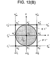
- FIG. 12 is schematic diagrams showing how an ellipse is projectively transformed into a circle, where FIG. 12(A) is a schematic diagram showing a quadrangle contacting with an ellipse and FIG. 12(B) is a schematic diagram showing the projectively-transformed quadrangle;
- FIG. 13(A) is a schematic diagram showing a plane for explaining a projective transformation matrix
- FIG. 13(B) is a schematic diagram showing a plane for explaining projective transformation in quadric curve
- FIG. 14 is a flowchart showing an exemplary subroutine for calculating a quadrangle in the flowchart of FIG. 8 ;
- FIG. 15 is a flowchart showing an exemplary subroutine for calculating a quadrangle in first and second variants for calculating a quadrangle contacting with an ellipse;
- FIG. 16 is a schematic diagram showing the first variant for calculating a quadrangle contacting with an ellipse
- FIG. 17 is a schematic diagram showing the second variant for calculating a quadrangle contacting with an ellipse
- FIG. 18 shows a third variant for calculating a quadrangle contacting with an ellipse, where FIG. 18(A) is a schematic diagram showing an exemplary quadrangle inscribed with an ellipse and FIG. 18(B) is a schematic diagram showing the projectively-transformed quadrangle; and
- FIG. 19 shows a fourth variant for calculating a quadrangle contacting with an ellipse
- FIG. 19(A) is a schematic diagram showing an exemplary quadrangle contacting with an ellipse
- FIG. 19(B) is a schematic diagram showing the projectively-transformed quadrangle.
- FIG. 1 is a schematic diagram showing an exemplary outline structure of the image searching system according to the embodiment of the present invention.
- FIG. 2 is a block diagram showing an exemplary outline structure of a portable terminal of FIG. 1 .
- the image searching system 1 as an exemplary image processing apparatus includes a portable terminal 10 for photographing a shooting target such as portable wireless phone, and an image searching server 20 for making a search based on image data from the portable terminal 10 .
- the portable terminal 10 functioning as an exemplary image processing apparatus has a photographing unit 11 for photographing a shooting target, a display unit 12 for displaying a photographed image or the like, a wireless communication unit 13 for communicating with a wireless base station, an operation unit 14 for inputting numerals or characters, a storage unit 15 for storing photographed images therein, and a control unit 16 for performing various controls on the portable terminal 10 , and the units are interconnected via a bus 17 .
- the photographing unit 11 has a digital camera formed of a CMOS (Complementary Metal Oxide Semiconductor) image sensor or a CCD (charge-coupled device) image sensor.
- CMOS Complementary Metal Oxide Semiconductor
- CCD charge-coupled device
- the display unit 12 is configured of a liquid crystal display device or EL (Electro Luminescence) device.
- the wireless communication unit 13 makes communication with the image searching server 20 via a mobile communication network 2 or a network 3 such as Internet.
- the operation unit 14 is configured of various keys. A user moves a pointer displayed on the display unit 12 , or selects and confirms an image portion by the operation unit 14 .
- the storage unit 15 has a nonvolatile memory such as RAM (Random Access Memory), ROM (Read Only Memory) or flash memory and forms therein a memory space into which an image processing program is loaded and which holds image data therein.
- RAM Random Access Memory
- ROM Read Only Memory
- flash memory forms therein a memory space into which an image processing program is loaded and which holds image data therein.
- the control unit 16 has a CPU (Central Processing Unit) and executes an image processing program as a computer.
- CPU Central Processing Unit
- the image searching server 20 functioning as a computer has a control unit 21 for controlling the entire image searching server 20 and making a calculation for the image processing, and a database 22 in which a database for image search is constructed.
- control unit 21 has a CPU 21 a for executing computer programs, and a memory 21 b such as nonvolatile memory including RAM, ROM or flash memory for storing programs to be executed therein.
- memory 21 b such as nonvolatile memory including RAM, ROM or flash memory for storing programs to be executed therein.
- the CPU 21 a in the control unit 21 searches information from the database 22 in response to a search request transmitted from the portable terminal 10 , performs an image processing of searching information from received image data, and manages the database 22 .
- a program for making an image search is developed, the received image data is stored, and a calculation result is temporarily stored.
- the database 22 has a hard disk drive or silicon disk, and stores information associated with the feature quantity of an image therein.
- the database 22 stores therein information on flowers' names and scientific names and flowers' image such as image on flowers, leaves and nuts in association with information on flowers' colors, numbers of flower petals and entire shapes of flowers and information on discontinuities of flower petals as the feature quantity required for identifying a flower.
- the portable terminal 10 is connected to the mobile communication network 2 , the image searching server 20 is connected to the network 3 such as Internet, and the mobile communication network 2 and the network 3 are interconnected via a gateway for converting a protocol or contents-describing language.
- FIG. 3 is a conceptual diagram showing a concept of how a subject is projected on a photograph when the subject is photographed from an observation point V 1 .
- image modification is made as if a flower image obliquely photographed from the observation point V 1 were seen from the front in a pseudo manner. It is assumed that the subject flower is approximated by an ellipse E 1 and is on the plane of a quadrangle P 1 ′.
- the entire flower and the center of the flower are extracted from the photographed image, and the respective contour curves are approximated to ellipses for a simplified method.
- the ellipse to which the entire flower is approximated corresponds to the ellipse E 1 and its center is a point O B .
- the center of the ellipse to which the center of the flower is approximated corresponds to a point O A .
- projective transformation is performed in order to obtain an apparent standard image (transformation image) from the front of the flower.
- the projective transformation corresponds to photographing an object in a 3D space into a 2D-plane film. Projection in the reverse direction, that is, from 2D to 3D is typically impossible, but is enabled under some limited conditions.
- the projective transformation is performed from the 2D plane to the 2D plane. Further, for simplifying the method, it is assumed that the shape of an actual flower can be approximated to a circle E 1 ′.
- the flower clipped from the input image is approximated to the ellipse E 1 , and the quadrangle P 1 circumscribed with the ellipse E 1 is obtained to be an target area to be modified.
- the target area to be modified is projectively transformed into the quadrangle P 1 ′ as square, the ellipse E 1 is projected to the previously-assumed circle E 1 ′.
- the projective transformation the standard image of the photograph of the flower taken from its front can be obtained in a pseudo manner from the photograph of the flower taken at a tilted angle. The method will be described in detail with the flowcharts.
- the standard image is an image transformed to be displayed in a desired orientation.
- the standard image is an image in which a flower is displayed at such an angle that the center of the flower is near the center of the entire flower, and may be an image viewed at an angle at which a target image such as flower can be easily specified.
- FIG. 4 is a flowchart showing an exemplary image processing by the portable terminal of FIG. 1 .
- FIG. 5(A) is a schematic diagram showing an exemplary image including a target image
- FIG. 5(B) is a schematic diagram showing how the target image extracted from the image is
- FIG. 5(C) is a schematic diagram showing how a center candidate image including a center candidate is extracted from the target image.
- FIG. 6 is a schematic diagram showing an exemplary projectively-transformed target image.
- the portable terminal 10 obtains an image of a shooting target by the photographing unit 11 (step S 1 ).
- the control unit 16 in the portable terminal 10 obtains an image including a target image (flower image) as shown in FIG. 5(A) from the photographing unit 11 , and stores image data of the image in the storage unit 15 .
- the portable terminal 10 functions as an exemplary image obtaining means that obtains the image including the target image, and functions as an exemplary storing means that stores therein the target image to be subjected to the image processing.
- the subject flower is not photographed from its front.
- the portable terminal 10 extracts the target image from the obtained image (step S 2 ).
- the control unit 16 finds the contour of the entire flower and extracts the flower image as shown in FIG. 5(B) .
- the entire flower characterized by its petals is drawn by the contour curve and its background is made dark.
- the user may designate the flower part and the background part by a pointer displayed on the display unit 12 by the operation unit 14 , and the control unit 16 may extract the target image based on the information on colors.
- the portable terminal 10 functions as an exemplary target image extracting means that extracts the target image from the obtained image.
- the target image extracting means includes a receiving means that receives, from the user, designations of at least one foreground pixel on a flower portion (foreground area) included in the obtained image and at least one background pixel on the background portion (background area) included in the obtained image, a divided color space specifying means that performs a divided color space specification processing of, with the designated foreground pixel and the designated background pixel as reference pixels, respectively, specifying a divided color space to which each reference pixel belongs as a reference divided color space from among multiple divided color spaces into which a 3D color space is divided, a color distance calculating means that performs a color distance calculation processing of calculating a color distance in a color space between each reference pixel and a neighboring pixel adjacent thereto, belonging a deciding means that performs a belonging decision processing of deciding whether each neighboring pixel belongs to each reference divided color space, a cost calculating means that performs a cost calculation processing of calculating cost of each neighboring pixel, based on
- the portable terminal 10 extracts a center candidate image from the target image (step S 3 ).
- the control unit 16 extracts the contour of the center of the flower as exemplary center candidate image, which is present on the contour of the entire flower.
- the user may designate the flower petals and the center of the flower by a pointer displayed on the display unit 12 by the operation unit 14 , and the control unit 16 may extract the target image based on the information on colors.
- the portable terminal 10 functions as an exemplary center candidate deciding means that extracts, from the target image, the center candidate image which is an image in a predetermined area including the center candidate.
- the center candidate image is, for example, an image of an area in a target image which includes the center candidate and in which depth or color information is discontinuously different from surroundings.
- the portable terminal 10 transforms the target image into the standard image (step S 4 ).
- the control unit 16 transforms the target image stored in the storage unit 15 into the standard image which seems to be the flower photographed from its front as shown in FIG. 6 .
- the portable terminal 10 functions as exemplary standard image obtaining means (transformation image obtaining means) for projectively transforming the target image stored in the storing means based on a projective transformation matrix and obtaining the standard image.
- the image data of the vicinity including the target image is transformed into the standard image.
- the portable terminal 10 transmits the standard image to the image searching server 20 for search (step S 5 ).
- the control unit 16 transmits the standard image as shown in FIG. 6 to the image searching server 20 from the wireless communication unit 13 via the mobile communication network 2 and the network 3 .
- the portable terminal 10 receives and displays the search result from the image searching server 20 (step S 6 ).
- the control unit 16 receives the name of the searched flower and the information on its flower from the image searching server 20 via the wireless communication unit 13 , and displays the same on the display unit 12 .
- a search processing by the image searching server 20 will be described below.
- FIG. 7 is a flowchart showing an exemplary search processing by the image searching server 20 .
- the image searching server 20 receives the standard image from the portable terminal 10 (step S 7 ). Specifically, the control unit 21 in the image searching server 20 receives the standard image from the portable terminal 10 via the mobile communication network 2 and the network 3 .
- the image searching server 20 extracts a feature quantity from the received standard image (step S 8 ). Specifically, when the target image is a flower image, the control unit 21 extracts the information on the number of flower petals, the flower color and the entire flower shape and the information on the flower petal such as discontinuities of the flower petal, as the feature quantity of the standard image.
- the image searching server 20 searches the information for specifying the standard image from the database 22 based on the feature quantity of the extracted standard image (step S 9 ). Specifically, the control unit 21 searches a similar flower from the database 22 based on the feature quantity of the standard image of the flower, and finds the information on flowers having a higher similarity and images of the flowers. In this way, the image searching server 20 functions as an exemplary searching means that searches the information for specifying the target image based on the standard image.
- the image searching server 20 functions as an exemplary searching means that extracts a feature quantity of the image from the standard image and searching the information for specifying the target image based on the feature quantity.
- the image searching server 20 transmits the results with a high search ranking to the portable terminal 10 (step S 10 ). Specifically, the control unit 21 transmits the information on flowers or the images of the flowers.
- the image searching server 20 functions as an exemplary searching means that searches the information for specifying the target image based on the standard image.
- the image searching server 20 functions as an exemplary searching means that extracts a feature quantity of the image from the standard image and searching the information for specifying the target image based on the feature quantity.
- the portable terminal 10 may include a database like the database 22 of the image searching server 20 , and may search the information on the image from the standard image.
- step S 4 for transforming the target image into the standard image will be described below in detail with reference to the drawings.
- FIG. 8 is a flowchart showing an exemplary subroutine for transformation into the standard image in the flowchart of FIG. 4 .
- FIG. 9(A) is a schematic diagram showing the contour of the target image of FIG. 5 and an exemplary ellipse by which the target image is approximated
- FIG. 5(B) is a schematic diagram showing a center candidate image including a center candidate extracted from the target image and an exemplary ellipse by which the center candidate image is approximated.
- FIG. 10 is a schematic diagram showing a relationship between the ellipse of FIG. 9(A) and the ellipse of FIG. 9(B) .
- FIG. 11 is a schematic diagram showing a relationship between the target image of FIG.
- FIG. 12 is schematic diagrams showing projective transformation from an ellipse into a circle, where FIG. 12(A) is a schematic diagram showing a quadrangle contacting with an ellipse and FIG. 12(B) is a schematic diagram showing the projectively-transformed quadrangle.
- the portable terminal 10 performs ellipse approximation on the target image and the center candidate image (step S 20 ). Specifically, the control unit 16 approximates the contour F 1 of the entire flower extracted in step S 2 to the ellipse E 1 by least square as shown in FIG. 9(A) , and approximates the contour F 2 of the center of the flower extracted in step S 3 to an ellipse E 2 by least square as shown in FIG. 9(B) . In this way, the portable terminal 10 functions as an exemplary ellipse calculating means that calculates the ellipse by which the target image is approximated. The ellipse approximation will be described later.
- the portable terminal 10 decides the center candidate (step S 21 ). Specifically, the control unit 16 decides the center candidate O A from the intersection point between the major axis E 2 A and the minor axis E 2 B of the ellipse E 2 by which the center of the flower is approximated as shown in FIG. 9(B) .
- the center candidate O A is information on depth.
- the relationship between the ellipse E 1 of the entire flower and the ellipse E 2 of the center of the flower is as shown in FIG. 10 .
- the portable terminal 10 functions as an exemplary center candidate deciding means that decides the center candidate of the target image.
- the portable terminal 10 functions as an exemplary center candidate deciding means that decides the center candidate from the intersection point between the major axis and the minor axis of the ellipse by which the extracted center candidate image is approximated.
- the portable terminal 10 functions as an exemplary ellipse calculating means that calculates the ellipse whose target image is a flower image and by which the flower image is approximated.
- the portable terminal 10 functions as an exemplary center candidate deciding means that decides the center candidate of the flower image inside of the center of the flower whose target image is the flower image.
- the portable terminal 10 calculates a quadrangle associated with the ellipse and the center candidate (step S 22 ). Specifically, as shown in FIG. 11 , the control unit 16 calculates the quadrangle P 1 as an exemplary first polygon contacting with the ellipse E 1 from the ellipse E 1 of the entire flower and the center candidate O A of the ellipse E 2 of the center of the flower. In this way, the portable terminal 10 functions as an exemplary polygon calculating means that calculates the first polygon associated with the ellipse and the center candidate. The portable terminal 10 functions as an exemplary polygon calculating means that calculates the quadrangle associated with the ellipse and the center candidate.
- the portable terminal 10 calculates a projective transformation matrix based on the quadrangle as an exemplary first polygon and a square as an exemplary second polygon (step S 23 ).
- the control unit 16 calculates the projective transformation matrix based on the vertexes x 2 , x 2 , x 3 , x 4 of the quadrangle P 1 as the first polygon and the vertexes x 2 ′, x 2 ′, x 3 ′, x 4 ′ of the square P 1 ′ as an exemplary second polygon.
- the portable terminal 10 functions as an exemplary projective transformation matrix calculating means that calculates the projective transformation matrix which projectively transforms the first polygon into the second polygon associated with the ellipse whose center is a point where the center candidate is projectively transformed.
- the portable terminal 10 functions as the projective transformation matrix calculating means that calculates the projective transformation matrix which projectively transforms the quadrangle into the square associated with the ellipse whose center is a point where the center candidate is projectively transformed.
- the second polygon is a regular polygon, for example.
- the center of the second polygon is the center of gravity, the incenter or the circumcenter of the second polygon as regular polygon, for example. In the embodiment, a square is employed as the second polygon.
- the square P 1 ′ as the second polygon is circumscribed with the ellipse (the circle in the embodiment) E 1 ′ whose center is a point where the center candidate is projectively transformed.
- the center of the ellipse is the intersection point between the major axis and the minor axis of the ellipse.
- the ellipse includes a circle in which the length of the major axis is the same as the length of the minor axis. The projective transformation matrix will be described later.
- the portable terminal 10 transforms the target image into the standard image based on the projective transformation matrix (step S 24 ).
- the control unit 16 transforms each pixel of the image data of the target image stored in the storage unit based on the projective transformation matrix for transforming the quadrangle P 1 (x 1 , x 2 , x 3 , x 4 ) into the square P 1 ′ (x 1 ′, x 2 ′, x 3 ′, x 4 ′).
- the portable terminal 10 decides whether the standard image needs to be corrected (step S 25 ). Specifically, the control unit 16 decides whether the standard image needs to be corrected based on an error between the ellipse approximation and the contour of the entire flower, a distortion of the standard image or a distortion of the center of the flower in the standard image.
- the control unit 16 receives an input from the operation unit 14 and decides whether the standard image needs to be corrected.
- the control unit 16 returns to step S 20 to adjust the shape of the ellipse and the position of the center candidate.
- step S 25 NO
- the control unit 16 terminates the subroutine.
- the quadric curve can be indicated by the following equation using the coefficients A to F.
- Ax 2 +2 Bxy+Cy 2 +2 Dx+ 2 Ey+F 0 (1)
- V+ is called pseudo inverse matrix.
- FIG. 13(A) is a schematic diagram showing a plane for explaining the projective transformation matrix
- FIG. 13(B) is a schematic diagram showing a plane for explaining the quadric curve projective transformation.
- the respective equations in the formula can be reduced with an arbitrary constant and are each made of an independent 8-coefficient.
- the eight points' coordinates are substituted into the equation (8) to solve the equation (8), thereby defining the projective transformation matrix P from the coefficients in the following.
- the matrix Q is defined by the coefficients A to F as follows.
- the quadric curve can keep its nature even when the projective transformation is applied thereto.
- FIG. 14 is a flowchart showing an exemplary subroutine for calculating a quadrangle in the flowchart of FIG. 8 .
- the target of the projective transformation is limited to an ellipse in the quadric curve and the virtual quadrangle (target area to be modified) P 1 obtained from the ellipse E 1 is projectively transformed into the square P 1 ′ with which the circle E 1 ′ is inscribed.
- the projective transformation from the ellipse E 1 into the circle E 1 ′ is assumed.
- the subroutine calculates the quadrangle P 1 in the target area to be modified by the following method.
- the portable terminal 10 first decides a first reference straight line passing through the center candidate (step S 30 ). Specifically, the control unit 16 in the portable terminal 10 decides an arbitrary straight line passing through the center candidate O A , for example, the first reference straight line l 0 parallel to the major axis E 1 A of the ellipse E 1 relative to the ellipse E 1 and its inner point (center candidate) O A as shown in FIG. 12(A) . In this way, the portable terminal 10 functions as an exemplary polygon calculating means that assumes a straight line parallel to the major axis of the ellipse as the straight line (the first reference straight line l 0 ) passing through the center candidate.
- the portable terminal 10 calculates a first tangent point and a second tangent point from the intersection points between the first reference straight line and the ellipse (step S 31 ). Specifically, the control unit 16 calculates the first tangent point q 1 and the second tangent point q 2 from the intersection points between the first reference straight line l 0 and the ellipse E 1 .
- the portable terminal 10 calculates a first tangential line at the first tangent point and a second tangential line at the second tangent point (step S 32 ). Specifically, the control unit 16 calculates the first tangential line m 1 of the ellipse E 1 at the first tangent point q 1 and the second tangential line m 2 of the ellipse E 1 at the second tangent point q 2 .
- the portable terminal 10 calculates a first vanishing point from the intersection point between the first tangential line and the second tangential line (step S 33 ).
- the control unit 16 calculates the first vanishing point q ⁇ from the intersection point between the first tangential line m 1 and the second tangential line m 2 .
- the first vanishing point q ⁇ is called pole and the reference straight line l 0 is called polar line, which are in a dual relationship in which one of them is defined and thereby the other is defined.
- the portable terminal 10 calculates a second reference straight line passing through the first vanishing point and the center candidate (step S 34 ). Specifically, the control unit 16 calculates the second reference straight line m 0 as the polar line passing through both the first vanishing point q ⁇ and the center candidate O A .
- the portable terminal 10 calculates third and fourth tangent points from the intersection points between the second reference straight line and the ellipse (step S 35 ). Specifically, the control unit 16 calculates the third tangent point p 1 and the fourth tangent point p 2 from the intersection points between the second reference straight line m 0 and the ellipse E 1 .
- the portable terminal 10 calculates a third tangential line at the third tangent point and a fourth tangential line at the fourth tangent point (step S 36 ). Specifically, the control unit 16 calculates the third tangential line l 1 of the ellipse E 1 at the third tangent point p 1 and the fourth tangential line l 2 of the ellipse E 1 at the fourth tangent point p 2 .
- the portable terminal 10 calculates a second vanishing point from the intersection point between the third tangential line and the fourth tangential line (step S 37 ). Specifically, the control unit 16 calculates the second vanishing point p ⁇ of the pole from the intersection point between the third tangential line l 1 and the fourth tangential line l 2 .
- the portable terminal 10 calculates the vertexes of the quadrangle from the intersection points between the first to fourth tangential lines (step S 38 ). Specifically, the control unit 16 calculates the intersection point x 1 between the first tangential line m 1 and the fourth tangential line l 2 , the intersection point x 2 between the fourth tangential line l 2 and the second tangential line m 2 , the intersection point x 3 between the second tangential line m 2 and the third tangential line l 1 , and the intersection point x 4 between the third tangential line l 1 and the second tangential line m 1 , and assumes the intersection points as the vertexes of the quadrangle P 1 .
- the quadrangle P 1 surrounded by the first to fourth tangential lines is the target area to be modified, and is an exemplary first polygon with the intersection points between the straight lines passing through the center candidate and the ellipse as tangent points.
- the portable terminal 10 functions as an exemplary polygon calculating means that calculates the quadrangle as an exemplary first polygon with the intersection points between the straight lines passing through the center candidate and the ellipse as tangent points.
- the control unit 16 calculates the projective transformation matrix P from the coordinates of the vertexes x 1 to x 4 of the quadrangle P 1 shown in FIG. 12(A) and the coordinates of the vertexes x 1 ′ to x 4 ′ of the square P 1 ′ shown in FIG. 12(B) in step S 23 after the subroutine.
- the projective transformation matrix P With the projective transformation matrix P, the ellipse E 1 is projectively transformed into the circle E 1 ′ as an exemplary standard image and at the same time the center candidate O A is projected onto the center O A ′ of the circle.
- the center candidate O A By use of the coordinate of the center of the flower positioned at the center of the flower, the center candidate O A can be appropriately taken.
- the quadrangle P 1 in the target area to be modified is obtained from the ellipse E 1 approximated from the entire flower and the center coordinate (the coordinate of the center candidate O A ) of the ellipse approximated from the center of the flower, and is projectively transformed into the square P 1 ′ so that the front view is obtained.
- the portable terminal 10 stores the target image to be subjected to the image processing in the storage unit 15 , calculates the ellipse E 1 by which the target image (such as the contour F 1 of the entire flower) is approximated, decides the center candidate O A of the target image, calculates the first polygon (such as the quadrangle P 1 ) associated with the ellipse and the center candidate, calculates the projective transformation matrix P for projectively transforming the first polygon into the second polygon (such as the square P 1 ′) associated with the ellipse whose center is a point where the center candidate is projectively transformed, and projectively transforms the target image stored in the storage unit 15 based on the projective transformation matrix thereby obtaining the transformation image of the target image so that even a target image having no contour of straight line portions such as flower can be transformed into an image displayed in a desired orientation.
- the first polygon such as the quadrangle P 1
- the second polygon such as the square P 1 ′
- the portable terminal 10 can transform the subject into the standard image which seems to be photographed from its front, that is, an image displayed in a desired orientation, and thus the user does not need to take into consideration the shooting angle, thereby alleviating a user's load.
- the subject is a flower
- the user put the flower on the black background or photographed the flower from its front over the entire screen.
- the user's load such as adjustment of angle during shooting was heavy. Since there are many flowers that are not easily photographed in mountain, in the related art, a previously-taken photograph was not be able to be corrected into an image displayed in a desired orientation.
- even a subject with no straight line portion can be transformed into an image which seems to be photographed from its front.
- the portable terminal 10 can change the orientation displayed in the photographed image after shooting, the user can photograph the subject without the need of taking into consideration the reflection of illumination, thereby enhancing user's convenience.
- the target image is transformed into an image which seems to be photographed from its front and the searching is made based on the transformation image, thereby facilitating the searching by the standardized feature quantity and enhancing the search speed and the search accuracy.
- the portable terminal 10 may include the database for search.
- the portable terminal 10 can easily and uniquely calculate the first polygon associated with the ellipse and the center candidate, thereby deciding the projective transformation matrix from the coordinates of the vertexes of the first polygon.
- the portable terminal 10 can function as the polygon calculating means which assumes a straight line parallel to the major axis E 1 A of the ellipse as the straight line l 0 passing through the center candidate O A , the portable terminal 10 can compute the standard image with less distortion and the transformed image can be easily viewed. Because of the standard image with less distortion, the search accuracy is also enhanced.
- the portable terminal 10 can easily calculate the four coordinates for computing the projective transformation matrix from the vertexes of the quadrangle P 1 .
- the portable terminal 10 can objectively obtain the information on depth from the center candidate and can obtain the standard image closer to the image photographed from its front.
- the portable terminal 10 can obtain the standard image of the flower such as the front image in which the flower is viewed from its pistil even when the image is limited in shooting place or angle.
- the portable terminal 10 can specify the kind of the flower or the like from the standard image of the flower.
- the portable terminal 10 can photograph the target image such as flower away from home such as in mountain, and can obtain the standard image in which the front image of the flower is displayed in a desired orientation on site, thereby easily specifying the target image, for example, specifying the kind of the flower.
- the portable terminal 10 can separate the background image and the target image and remove an influence of the background image, thereby obtaining the standard image with good accuracy and enhancing the search accuracy based on the standard image.
- the user can photograph the target image without the need of taking into consideration the contrast and the portable terminal 10 can alleviate the user's load during the photographing.
- the image searching server 20 can search the information on the images also in mountain in response to the reception of the search result by the portable terminal 10 , and can construct the system capable of easily searching the information on the flower from the photographs of the flowers taken in mountain, for example. Since the target image is specified based on the standard image which seems to be photographed from its front, for example, the searching can be made by the standardized feature quantity, thereby enhancing the search speed and the search accuracy or simplifying the database.
- the image searching server 20 can enhance the search accuracy.
- FIG. 15 is a flowchart showing an exemplary subroutine for calculating a quadrangle according to first and second variants for calculating a quadrangle contacting with an ellipse.
- FIG. 16 is a schematic diagram showing the first variant for calculating a quadrangle contacting with an ellipse.
- FIG. 17 is a schematic diagram showing the second variant for calculating a quadrangle contacting with an ellipse.
- the portable terminal 10 decides the first tangent point and the first tangential line which is horizontal to the image frame and contact with the ellipse (step S 40 ). Specifically, the control unit 16 in the portable terminal 10 decides the first tangent point q 2 and the first tangential line m 2 which are horizontal to the upper side 30 a or lower side of the image frame 30 and contact with the ellipse E 1 as shown in FIG. 16 .
- the image frame 30 is a rectangular frame surrounding the photographed 2D entire image, for example.
- the portable terminal 10 calculates the first reference straight line passing through the first tangent point and the center candidate (step S 41 ). Specifically, the control unit 16 calculates the first reference straight line l 0 passing through the first tangent point q 2 and the center candidate O A .
- the portable terminal 10 calculates the second tangent point and the second tangential line from the first reference straight line and the ellipse (step S 42 ). Specifically, the control unit 16 calculates the second tangent point q 1 from the intersection point between the first reference straight line l 0 and the ellipse E 1 , and calculates the second tangential line m 1 contacting with the ellipse E 1 at the second tangent point q 1 .
- the portable terminal 10 calculates the first vanishing point from the intersection point between the first tangential line and the second tangential line (step S 43 ). Specifically, the control unit 16 calculates the first vanishing point q ⁇ from the intersection point between the first tangential line m 2 and the second tangential line m 1 .
- Step S 44 to step S 48 are the same as step S 34 to step S 38 , and finally the quadrangle P 2 as shown in FIG. 16 can be obtained.
- the portable terminal 10 functions as an exemplary polygon calculating means that calculates the quadrangle as an exemplary first polygon whose tangent point q 2 is the intersection point between the straight line passing through the center candidate O A and the ellipse E 1 .
- the portable terminal 10 functions as an exemplary polygon calculating means that uses, as the tangent point q 2 , the point where the straight line m 2 parallel to any side 30 a of the image frame 30 surrounding the target image contacts with the ellipse E 1 .
- the standard image with less image rotation in the circumferential direction can be obtained for the target image.
- the user can easily compare the target image with the obtained standard image, thereby easily editing the image.
- the portable terminal 10 functions as an exemplary polygon calculating means that calculates the quadrangle as an exemplary first polygon whose tangent point q 1 is the intersection point between the straight line passing through the center candidate O A and the ellipse E 1 .
- the portable terminal 10 functions as an exemplary polygon calculating means that uses, as the tangent point q 1 , the point where the straight line m 1 parallel to any side 30 a of the image frame 30 surrounding the target image contacts with the ellipse E 1 .
- the reference straight lines l 0 , m 0 may be arbitrary straight lines passing through the center candidate O A and may intersect with each other at the center candidate O A , and thus various lines can be taken.
- FIG. 18 shows the third variant for calculating a quadrangle contacting with an ellipse
- FIG. 18(A) is a schematic diagram showing an exemplary quadrangle inscribed with an ellipse
- FIG. 18(B) is a schematic diagram showing the projectively-transformed quadrangle.
- the quadrangle for calculating the projective transformation matrix P is a quadrangle P 4 having the tangent points p 1 , q 1 , p 2 and q 2 as the vertexes.
- the quadrangle P 4 is inscribed with the ellipse E 1 .
- the second polygon for calculating the projective transformation matrix P is a square P 4 ′ which has the tangent points p 1 ′, q 1 ′, p 2 ′ and q 2 ′ as the vertexes and is inscribed with the circle E 1 ′ as shown in FIG. 18(B) .
- the projective transformation matrix calculating means calculates the projective transformation matrix for projectively transforming the quadrangle P 4 into the square P 4 ′ inscribed with the ellipse (the circle E 1 ′ in the present variant) whose center is the point O A ′ where the center candidate O A is projectively transformed.
- step S 35 or step S 45 if the first tangent point, the second tangent point, the third tangent point and the fourth tangent point are found, the vertexes of the quadrangle P 4 are calculated.
- the portable terminal 10 functions as an exemplary polygon calculating means that calculates the first polygon associated with the ellipse and the center candidate.
- the portable terminal 10 functions as an exemplary polygon calculating means that calculates the quadrangle as an exemplary first polygon whose tangent points are the intersection points between the straight lines passing through the center candidate and the ellipse.
- the vertexes of the quadrangle P 4 for calculating the projective transformation matrix P are easily obtained as the first tangent point, the second tangent point, the third tangent point and the fourth tangent point.
- FIG. 19 shows the fourth variant for calculating a quadrangle contacting with an ellipse
- FIG. 19(A) is a schematic diagram showing an exemplary quadrangle contacting with an ellipse
- FIG. 19(B) is a schematic diagram showing the projectively-transformed quadrangle.
- the present variant is a case in which the center candidate O A is near the edge of the ellipse E 1 as shown in FIG. 19(A) .
- the quadrangle circumscribed with the ellipse E 1 is a quadrangle P 5 and the quadrangle inscribed with the ellipse E 1 is a quadrangle P 6 .
- the first reference straight line l 0 and the second reference straight line m 0 are found as arbitrary straight lines passing through the center candidate O A and as the lines intersecting with each other at the center candidate O A .
- the quadrangle P 5 circumscribed with the ellipse E 1 at the tangent points p 1 , q 1 , p 2 and q 2 does not surround the ellipse E 1 .
- the second polygon for calculating the projective transformation matrix P has the coordinate ( ⁇ , ⁇ ) of x 3 ′ corresponding to the vertex x 3 , and is conceptually a second polygon P 5 ′ as indicated with a dotted line in FIG. 19(B) . In this way, even when the quadrangle P 5 does not surround the ellipse E 1 , the projective transformation matrix P can be calculated.
- the projective transformation matrix calculating means calculates the projective transformation matrix for projectively transforming the quadrangle P 5 into the polygon P 5 ′ associated with the ellipse (the circle E 1 ′ in the present variant) whose center is the point O A ′ where the center candidate O A is projectively transformed.
- the second polygon for calculating the projective transformation matrix P is the square P 6 ′ which has the tangent points p 1 ′, q 1 ′, p 2 ′ and q 2 ′ as the vertexes and is inscribed with the circle E 1 ′ as shown in FIG. 19(B) .
- the inscribed quadrangle P 6 even when the center candidate is near the edge of the ellipse, the second polygon can be intuitively recognized.
- the projective transformation matrix calculating means calculates the projective transformation matrix for projectively transforming the quadrangle P 6 into the square P 6 ′ circumscribed with the ellipse (the circle E 1 ′ in the present variant) whose center is the point O A ′ where the center candidate O A is projectively transformed.
- An exemplary polygon may be a triangle or pentagon.
- at least four coordinates may only be decided in association with the ellipse E 1 and the center candidate O A for the target image before the transformation.
- a point on a side, the center of gravity, the incenter or the circumcenter of the triangle may be the fourth coordinate in addition to the three vertexes.
- the second polygon may only be an equiangular polygon such as regular triangle, square, rectangle, regular pentagon, or a regular polygon, or may be a figure associated with the projectively-transformed circle E 1 ′, and a figure to be able to calculate the projective transformation matrix P.
- the second polygon is not limited to a regular polygon.
- the ellipse inscribed or circumscribed with the second polygon, whose center is the point where the center candidate is projectively transformed, is not limited to a circle.
- the image searching server 20 may compute the standard image as the transformation image displayed in a desired orientation from the target image as an image processing apparatus. For example, the portable terminal 10 transmits the image data including the photographed target image as the search-requested image to the image searching server 20 via the network 3 .
- the reception unit in the image searching server 20 functions as image obtaining means to transform the image into the standard image at the image searching server 20 side, and the image searching server 20 makes a search based on the standard image.
- the image searching server 20 transmits the search result to the portable terminal 10 .
- the processings by the image searching server 20 in the image searching system 1 may be performed in a single server or may be distributed in a plurality of servers.
- the searching server may not be provided, the standard image may be simply obtained, for example, or the obtained standard image may be used to perform a different processing from the searching.
- the target image is not limited to a flower image and may be other circular shape such as dish, cup, CD, DVD, clockface or roadway sign.
- the target image is not limited to a flower image and may be an elliptical or planar object, for example.
- the present invention is not limited to the above embodiment.
- the above embodiment is exemplary and any embodiment having substantially the same structure as the technical spirit described in claims of the present invention and having similar operational effects may be encompassed in the technical range of the present invention.
Landscapes
- Engineering & Computer Science (AREA)
- Multimedia (AREA)
- Signal Processing (AREA)
- Physics & Mathematics (AREA)
- General Physics & Mathematics (AREA)
- Theoretical Computer Science (AREA)
- Image Processing (AREA)
- Image Analysis (AREA)
- Editing Of Facsimile Originals (AREA)
- Studio Devices (AREA)
Applications Claiming Priority (3)
| Application Number | Priority Date | Filing Date | Title |
|---|---|---|---|
| JP2009-241233 | 2009-10-20 | ||
| JP2009241233A JP5075182B2 (ja) | 2009-10-20 | 2009-10-20 | 画像処理装置、画像処理方法、および、画像処理プログラム |
| PCT/JP2010/068281 WO2011049046A1 (ja) | 2009-10-20 | 2010-10-18 | 画像処理装置、画像処理方法、画像処理プログラム、および、記録媒体 |
Publications (2)
| Publication Number | Publication Date |
|---|---|
| US20120201423A1 US20120201423A1 (en) | 2012-08-09 |
| US8660309B2 true US8660309B2 (en) | 2014-02-25 |
Family
ID=43900272
Family Applications (1)
| Application Number | Title | Priority Date | Filing Date |
|---|---|---|---|
| US13/502,972 Active 2030-12-09 US8660309B2 (en) | 2009-10-20 | 2010-10-18 | Image processing apparatus, image processing method, image processing program and recording medium |
Country Status (9)
Families Citing this family (25)
| Publication number | Priority date | Publication date | Assignee | Title |
|---|---|---|---|---|
| TWI476730B (zh) * | 2012-10-31 | 2015-03-11 | Vivotek Inc | 數位影像的反扭曲處理方法 |
| CN106296578B (zh) * | 2015-05-29 | 2020-04-28 | 阿里巴巴集团控股有限公司 | 一种图像处理方法及装置 |
| US10192129B2 (en) * | 2015-11-18 | 2019-01-29 | Adobe Systems Incorporated | Utilizing interactive deep learning to select objects in digital visual media |
| US11568627B2 (en) | 2015-11-18 | 2023-01-31 | Adobe Inc. | Utilizing interactive deep learning to select objects in digital visual media |
| CN107767326B (zh) * | 2017-09-28 | 2021-11-02 | 北京奇虎科技有限公司 | 图像中对象变换处理方法、装置及计算设备 |
| CN108038880B (zh) * | 2017-12-20 | 2019-12-13 | 百度在线网络技术(北京)有限公司 | 用于处理图像的方法和装置 |
| RU2680765C1 (ru) * | 2017-12-22 | 2019-02-26 | Общество с ограниченной ответственностью "Аби Продакшн" | Автоматизированное определение и обрезка неоднозначного контура документа на изображении |
| JP6730379B2 (ja) | 2018-03-23 | 2020-07-29 | 株式会社東芝 | 読取システム、読取方法、プログラム、及び記憶媒体 |
| WO2019181337A1 (ja) | 2018-03-23 | 2019-09-26 | 株式会社 東芝 | 読取システム、読取方法、及び記憶媒体 |
| JP6609345B2 (ja) | 2018-04-27 | 2019-11-20 | 株式会社東芝 | 読取システム、読取方法、プログラム、及び記憶媒体 |
| CN110650239B (zh) * | 2018-06-26 | 2021-03-16 | 百度在线网络技术(北京)有限公司 | 图像处理方法、装置、计算机设备及存储介质 |
| CN109003327B (zh) * | 2018-06-29 | 2022-09-30 | 平安科技(深圳)有限公司 | 图像处理方法、装置、计算机设备及存储介质 |
| JP6818002B2 (ja) * | 2018-12-12 | 2021-01-20 | 株式会社東芝 | 読取支援システム、移動体、読取支援方法、プログラム、及び記憶媒体 |
| US11282208B2 (en) | 2018-12-24 | 2022-03-22 | Adobe Inc. | Identifying target objects using scale-diverse segmentation neural networks |
| JP6763060B1 (ja) | 2019-05-27 | 2020-09-30 | 株式会社東芝 | 読取システム、移動体、読取方法、プログラム、及び記憶媒体 |
| CN110659370B (zh) * | 2019-08-12 | 2024-04-02 | 深圳市华付信息技术有限公司 | 一种高效数据标注方法 |
| CN113327863B (zh) * | 2020-02-28 | 2022-06-21 | 芯恩(青岛)集成电路有限公司 | 半导体工艺方法 |
| CN113469872B (zh) * | 2020-03-31 | 2024-01-19 | 广东博智林机器人有限公司 | 一种区域显示方法、装置、设备及存储介质 |
| US11335004B2 (en) | 2020-08-07 | 2022-05-17 | Adobe Inc. | Generating refined segmentation masks based on uncertain pixels |
| JP2022036839A (ja) * | 2020-08-24 | 2022-03-08 | セイコーエプソン株式会社 | 画像処理装置、画像処理方法および画像処理プログラム |
| US11676279B2 (en) | 2020-12-18 | 2023-06-13 | Adobe Inc. | Utilizing a segmentation neural network to process initial object segmentations and object user indicators within a digital image to generate improved object segmentations |
| CN113763439B (zh) * | 2021-02-07 | 2025-03-18 | 北京沃东天骏信息技术有限公司 | 图像处理方法和装置 |
| US11875510B2 (en) | 2021-03-12 | 2024-01-16 | Adobe Inc. | Generating refined segmentations masks via meticulous object segmentation |
| US12020400B2 (en) | 2021-10-23 | 2024-06-25 | Adobe Inc. | Upsampling and refining segmentation masks |
| WO2024089763A1 (ja) * | 2022-10-25 | 2024-05-02 | 日本電信電話株式会社 | 矩形領域推定装置、矩形領域推定方法及びプログラム |
Citations (10)
| Publication number | Priority date | Publication date | Assignee | Title |
|---|---|---|---|---|
| JPH0290378A (ja) | 1988-09-28 | 1990-03-29 | Agency Of Ind Science & Technol | 円の3次元計測方法 |
| JP2002203242A (ja) | 2000-12-28 | 2002-07-19 | Japan Science & Technology Corp | 植物認識システム |
| JP2005122320A (ja) | 2003-10-14 | 2005-05-12 | Casio Comput Co Ltd | 撮影装置、その画像処理方法及びプログラム |
| US20050190986A1 (en) * | 2004-02-27 | 2005-09-01 | Casio Computer Co., Ltd. | Image processing device, image projection apparatus, image processing method, recording medium, and computer data signal |
| JP2006277293A (ja) | 2005-03-29 | 2006-10-12 | Dainippon Printing Co Ltd | 回転体の三次元情報復元装置 |
| US7218775B2 (en) * | 2001-09-17 | 2007-05-15 | Her Majesty The Queen In Right Of Canada, As Represented By The Minister Of Agriculture And Agrifood | Method and apparatus for identifying and quantifying characteristics of seeds and other small objects |
| JP2007200020A (ja) | 2006-01-26 | 2007-08-09 | Nikon Corp | 対象物認識システム |
| US20070216784A1 (en) | 2006-03-17 | 2007-09-20 | Casio Computer Co., Ltd. | Imaging apparatus, picked-up image correcting method, and program product |
| JP2007251720A (ja) | 2006-03-17 | 2007-09-27 | Nikon Corp | 対象物認識システム |
| US20090225180A1 (en) * | 2005-08-25 | 2009-09-10 | Ricoh Company, Ltd. | Image processing method and apparatus, digital camera, and recording medium recording image processing program |
-
2009
- 2009-10-20 JP JP2009241233A patent/JP5075182B2/ja active Active
-
2010
- 2010-10-18 WO PCT/JP2010/068281 patent/WO2011049046A1/ja active Application Filing
- 2010-10-18 CN CN201080053867.3A patent/CN102656605B/zh active Active
- 2010-10-18 CA CA2776881A patent/CA2776881C/en active Active
- 2010-10-18 KR KR1020127012887A patent/KR101379066B1/ko active Active
- 2010-10-18 US US13/502,972 patent/US8660309B2/en active Active
- 2010-10-18 ES ES10824895.6T patent/ES2694762T3/es active Active
- 2010-10-18 EP EP10824895.6A patent/EP2477152B1/en active Active
- 2010-10-20 TW TW099135750A patent/TWI434567B/zh active
Patent Citations (12)
| Publication number | Priority date | Publication date | Assignee | Title |
|---|---|---|---|---|
| JPH0290378A (ja) | 1988-09-28 | 1990-03-29 | Agency Of Ind Science & Technol | 円の3次元計測方法 |
| JP2002203242A (ja) | 2000-12-28 | 2002-07-19 | Japan Science & Technology Corp | 植物認識システム |
| US7218775B2 (en) * | 2001-09-17 | 2007-05-15 | Her Majesty The Queen In Right Of Canada, As Represented By The Minister Of Agriculture And Agrifood | Method and apparatus for identifying and quantifying characteristics of seeds and other small objects |
| JP2005122320A (ja) | 2003-10-14 | 2005-05-12 | Casio Comput Co Ltd | 撮影装置、その画像処理方法及びプログラム |
| US20050190986A1 (en) * | 2004-02-27 | 2005-09-01 | Casio Computer Co., Ltd. | Image processing device, image projection apparatus, image processing method, recording medium, and computer data signal |
| JP2006277293A (ja) | 2005-03-29 | 2006-10-12 | Dainippon Printing Co Ltd | 回転体の三次元情報復元装置 |
| US20090225180A1 (en) * | 2005-08-25 | 2009-09-10 | Ricoh Company, Ltd. | Image processing method and apparatus, digital camera, and recording medium recording image processing program |
| JP2007200020A (ja) | 2006-01-26 | 2007-08-09 | Nikon Corp | 対象物認識システム |
| US20070216784A1 (en) | 2006-03-17 | 2007-09-20 | Casio Computer Co., Ltd. | Imaging apparatus, picked-up image correcting method, and program product |
| JP2007251700A (ja) | 2006-03-17 | 2007-09-27 | Casio Comput Co Ltd | デジタルカメラ及び画像処理プログラム |
| JP2007251720A (ja) | 2006-03-17 | 2007-09-27 | Nikon Corp | 対象物認識システム |
| US7961241B2 (en) * | 2006-03-17 | 2011-06-14 | Casio Computer Co., Ltd. | Image correcting apparatus, picked-up image correcting method, and computer readable recording medium |
Non-Patent Citations (4)
| Title |
|---|
| Kenneth Auvil, "Perspective Drawing," 2nd Ed., pp. 27-29 and 35-41. |
| Morde et al., "A Novel Approach to Planar Camera Calibration," pp. 1-6. |
| Obdrzalek et al., "Object Recognition Using Local Affine Frames on Maximally Stable Extremal Regions," J. Ponce et al. (Eds.): Toward Category-Level Object Recognition, LNCS 4170, 2006, pp. 83-104. |
| Treibergs et al., "The Geometry Perspective Drawing on the Computer," Mathematics of Perspective Drawing, 2007, pp. 1-18. |
Also Published As
| Publication number | Publication date |
|---|---|
| TWI434567B (zh) | 2014-04-11 |
| EP2477152A4 (en) | 2014-01-15 |
| ES2694762T3 (es) | 2018-12-27 |
| KR20120083486A (ko) | 2012-07-25 |
| EP2477152A1 (en) | 2012-07-18 |
| CN102656605B (zh) | 2015-12-16 |
| EP2477152B1 (en) | 2018-10-17 |
| KR101379066B1 (ko) | 2014-03-28 |
| JP5075182B2 (ja) | 2012-11-14 |
| TW201143352A (en) | 2011-12-01 |
| JP2011090374A (ja) | 2011-05-06 |
| CN102656605A (zh) | 2012-09-05 |
| CA2776881A1 (en) | 2011-04-28 |
| WO2011049046A1 (ja) | 2011-04-28 |
| US20120201423A1 (en) | 2012-08-09 |
| CA2776881C (en) | 2016-01-05 |
Similar Documents
| Publication | Publication Date | Title |
|---|---|---|
| US8660309B2 (en) | Image processing apparatus, image processing method, image processing program and recording medium | |
| CN109167924B (zh) | 基于混合相机的视频成像方法、系统、设备及存储介质 | |
| US8818101B1 (en) | Apparatus and method for feature matching in distorted images | |
| WO2018214365A1 (zh) | 图像校正方法、装置、设备、系统及摄像设备和显示设备 | |
| CN109474780B (zh) | 一种用于图像处理的方法和装置 | |
| CN104867113B (zh) | 图像透视畸变校正的方法及系统 | |
| JP2007183949A (ja) | イメージマッチング速度とブレンディング方法を改善したパノラマ映像提供方法および装置 | |
| JP2014071850A (ja) | 画像処理装置、端末装置、画像処理方法、およびプログラム | |
| CN107103056B (zh) | 一种基于局部标识的双目视觉室内定位数据库建立方法及定位方法 | |
| US10482571B2 (en) | Dual fisheye, hemispherical image projection and stitching method, device and computer-readable medium | |
| CN111598777A (zh) | 天空云图的处理方法、计算机设备和可读存储介质 | |
| CN104102732B (zh) | 图像展现方法及装置 | |
| CN105227948B (zh) | 一种查找图像中畸变区域的方法及装置 | |
| CN114140771A (zh) | 一种图像深度数据集自动标注方法及系统 | |
| US20140085303A1 (en) | Splitting of elliptical images | |
| US9852542B1 (en) | Methods and apparatus related to georeferenced pose of 3D models | |
| CN114157848B (zh) | 投影设备校正方法、装置、存储介质以及投影设备 | |
| CN114066731B (zh) | 生成全景图的方法、装置、电子设备及存储介质 | |
| CN113344789B (zh) | 图像拼接方法及装置、电子设备、计算机可读存储介质 | |
| TW201342303A (zh) | 三維空間圖像的獲取系統及方法 | |
| CN107431744A (zh) | 相机装置、图像处理装置以及图像处理方法 | |
| CN115797210A (zh) | 用于水下拍摄图片的校正方法、装置及存储介质 | |
| CN114845055A (zh) | 图像采集设备的拍摄参数的确定方法、装置及电子设备 | |
| CN111131689B (zh) | 全景图像修复方法和系统 | |
| CN107665481B (zh) | 图像处理方法、系统、处理设备及电子设备 |
Legal Events
| Date | Code | Title | Description |
|---|---|---|---|
| AS | Assignment |
Owner name: RAKUTEN, INC., JAPAN Free format text: ASSIGNMENT OF ASSIGNORS INTEREST;ASSIGNORS:ONAI, RIKIO;SATO, TOMOHIRO;MORI, MASAYA;AND OTHERS;REEL/FRAME:028082/0648 Effective date: 20120406 |
|
| STCF | Information on status: patent grant |
Free format text: PATENTED CASE |
|
| FEPP | Fee payment procedure |
Free format text: PAYOR NUMBER ASSIGNED (ORIGINAL EVENT CODE: ASPN); ENTITY STATUS OF PATENT OWNER: LARGE ENTITY |
|
| FPAY | Fee payment |
Year of fee payment: 4 |
|
| MAFP | Maintenance fee payment |
Free format text: PAYMENT OF MAINTENANCE FEE, 8TH YEAR, LARGE ENTITY (ORIGINAL EVENT CODE: M1552); ENTITY STATUS OF PATENT OWNER: LARGE ENTITY Year of fee payment: 8 |
|
| AS | Assignment |
Owner name: RAKUTEN GROUP, INC., JAPAN Free format text: CHANGE OF NAME;ASSIGNOR:RAKUTEN, INC.;REEL/FRAME:058314/0657 Effective date: 20210901 |
|
| AS | Assignment |
Owner name: RAKUTEN GROUP, INC., JAPAN Free format text: CORRECTIVE ASSIGNMENT TO CORRECT THE REMOVE PATENT NUMBERS 10342096;10671117; 10716375; 10716376;10795407;10795408; AND 10827591 PREVIOUSLY RECORDED AT REEL: 58314 FRAME: 657. ASSIGNOR(S) HEREBY CONFIRMS THE ASSIGNMENT;ASSIGNOR:RAKUTEN, INC.;REEL/FRAME:068066/0103 Effective date: 20210901 |
|
| MAFP | Maintenance fee payment |
Free format text: PAYMENT OF MAINTENANCE FEE, 12TH YEAR, LARGE ENTITY (ORIGINAL EVENT CODE: M1553); ENTITY STATUS OF PATENT OWNER: LARGE ENTITY Year of fee payment: 12 |